Page 1
I N S T A L L A T I O N I N S T R U C T I O N S Instrucciones de instalación Istruzioni di installazione Installationsanleitung Installatie-instructies Instruções de Instalação Instructions d´installation 
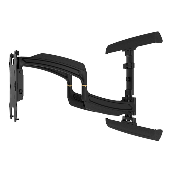
TS318SU (single stud) TS318TU (dual stud) TS325TU (dual stud) Medium Swing Arm Mounts Spanish Product Description German Product Description Portuguese Product Description...
5/8" (1.6cm) when installing any of the mounts to wood studs. If installing the TS318SU mount to poured concrete or hollow concrete, the wall CANNOT have ANY drywall covering! For the TS318TU and TS325TU, the wall CANNOT have ANY drywall covering if installing to poured concrete but may have a maximum drywall thickness of 5/8"...
Z (1) CC (1) K (4) 1/8" [shoulder washer] J (4) 1/4" [latch spacer] 5/32" EE (4) DD (2) * hardware bag for TS318SU includes only 2 lag screws [long adhesive] [short adhesive] and anchors and no installation washers.
Install TS318TU or TS325TU (Dual Stud) to Wall Tighten two screws (F) to secure upper wall rail (N) to wall. (See Figure 2) NOTE: If installing TS318SU, proceed to Install TS318SU (Single Stud) to Wall section. Install Wall Plate to Wall - Wood Studs (F) x 2...
Page 9
Installation Instructions TS318SU/TS318TU/TS325TU Install Wall Plate to Wall - Hollow Concrete Block or Poured Concrete (Important!- Read warnings below for drywall restrictions!) WARNING: Failure to provide adequate structural strength for this component can result in serious personal injury or (F) x 2 damage to equipment! It is the installer’s responsibility to...
Page 10
TS318SU/TS318TU/TS325TU Installation Instructions Install two concrete anchors (G) into two drilled holes. (See Figure 7) Loosely attach wall rail (N) to wall by installing two center of wall rail 5/16 x 2-1/2" flange head lag screws (F) into concrete anchors (G). (See Figure 7)
Page 11
Installation Instructions TS318SU/TS318TU/TS325TU 15. Loosely install two 5/16 x 2 1/2" flange head lag screws (F) Install TS318SU (Single Stud) to Wall through lower wall rail on main assembly and into concrete anchors. (See Figure 10) Install Wall Plate to Wall - Wood Studs 16.
Page 12
TS318SU/TS318TU/TS325TU Installation Instructions Install one 5/16- 2 1/2" flange head lag screw (F) into hole, Snap lag screw cover (U) onto wall mount over top lag leaving screw hanging out 1/2" from the wall. (See Figure 13) screw. (See Figure 15) Hang main assembly (M) onto lag screw (F) by latching key- shaped hole over top of screw.
Page 13
Installation Instructions TS318SU/TS318TU/TS325TU 6 1/8" Figure 18 Install the other concrete anchor into drilled hole. (See Figure 18) Figure 16 10. Place main assembly back onto wall. (See Figure 18) Install one concrete anchor (G) into drilled hole. (See 11. Install 5/16-2 1/2" hex flange lag screw (F) into concrete Figure 17) anchor to secure main assembly to wall.
TS318SU/TS318TU/TS325TU Installation Instructions Interface Installation IMPORTANT ! : If the display hole pattern size is 100mm (A-C) x4,x6,x8 or (D) x4 x 100mm, 200mm x 200mm or 100mm x 200mm, the display can be mounted directly to the faceplate and the...
Page 15
Installation Instructions TS318SU/TS318TU/TS325TU Connect bottom interface support (S) to uprights (P and Q) using four #10-24 x 1/2" button head cap screws (W). (See Figure 22) 10. When connecting bottom interface support to uprights, (W) x 4 make sure that it is aligned vertically with top interface support.
Page 16
TS318SU/TS318TU/TS325TU Installation Instructions Installing Display Without Interface Bracket Tighten all hardware to ensure display is securely mounted. (100x100, 200x200 or 200x100) (200 x 200 shown) CAUTION: Using screws of improper diameter may damage your display! Proper screws will easily thread into display mounting holes.
Installation Instructions TS318SU/TS318TU/TS325TU Cable Management Creating Space Make all cable connections to display. In order to create more space between display and wall, spacers may be added. Open cable management covers on upper and lower swing arms by unhinging center tabs and lifting covers to the open Extend swing arms in order to gain access to the center position.
TS318SU/TS318TU/TS325TU Installation Instructions Height Adjustment Tilt Friction Adjustment Extend swing arms in order to gain access to the center Tilt display forward enough to expose screws on the side of support. tilting mechanism. (See Figure 32) Use 1/4" hex key (BB) to adjust height adjustment screw to Adjust tilt friction adjustment screw to increase or decrease raise or lower mount to desired height.
Page 19
Installation Instructions TS318SU/TS318TU/TS325TU Use 9/16" wrench to adjust arm tension directly behind faceplate. (See Figure 35) arm tension adjustment points (swing arms not shown for display purposes) Figure 35 Install Interface Bracket Adhesive Covers (Optional) If the interface bracket was required to install display to mount, adhesive covers may be used to cover the holes on the interface bracket in order to improve the appearance.
Page 20
Europe A Franklinstraat 14, 6003 DK Weert, Netherlands P +31 (0) 495 580 852 F +31 (0) 495 580 845 Chief, a products division of Asia Pacific A Office No. 918 on 9/F, Shatin Galleria Milestone AV Technologies 18-24 Shan Mei Street...
Need help?
Do you have a question about the TS318SU and is the answer not in the manual?
Questions and answers