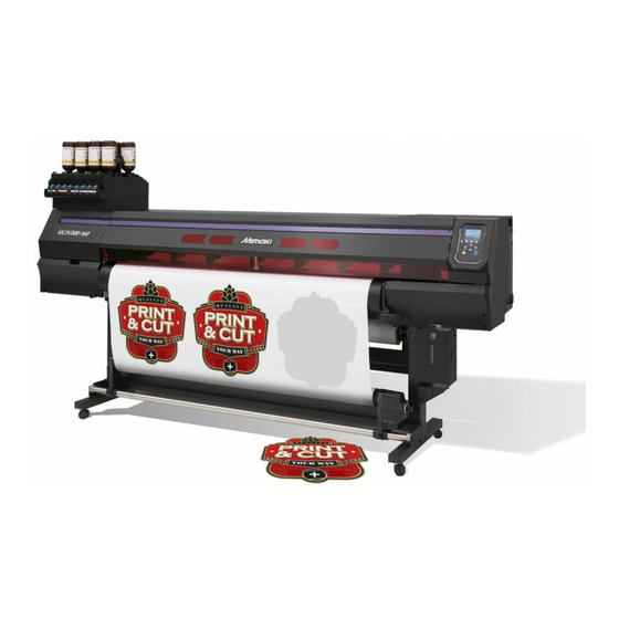
MIMAKI UCJV300 Series Operation Manual
Uv inkjet printer
Hide thumbs
Also See for UCJV300 Series:
- Operation manual (194 pages) ,
- Care and maintenance (36 pages) ,
- Manual (22 pages)

Related Manuals for MIMAKI UCJV300 Series


Summary of Contents for MIMAKI UCJV300 Series
- Page 1 You can also download the latest manual from official website. MIMAKI ENGINEERING CO., LTD. https://mimaki.com/ D203176-25 Original instructions...
-
Page 2: Table Of Contents
TABLE OF CONTENTS Introduction .................. 6 For safe use.................. 8 Symbols .................... 8 Usage Precautions ................ 9 Ink and other liquids used with this machine ........ 12 Ink Specifications................ 13 Restrictions concerning the product ........... 13 Installation Precautions.............. 15 Installation Space ................ 16 When Relocating This Machine ............ - Page 3 2.3 Adjusting the Pinch Roller Positions ........ 54 1,600 mm size .................. 55 1,300 mm size .................. 56 1,070 mm size .................. 57 750 mm size .................. 58 2.4 Loading the Media .............. 59 Media .................... 59 Loading the Roll Media ............... 59 Setting Leaf Media................
- Page 4 4.2 Creating Register Marks ............ 98 Register marks.................. 98 Register Mark Size ................ 99 Spacing Between Register Marks............ 99 Reading Range of Register Marks............ 100 No-Plotting Areas Around Register Marks........ 102 Combined Operations of Printing and Cutting ........ 102 4.3 Setting Mark Detection Conditions ........ 103 4.4 Detecting the Position of the Register Mark Origin....
- Page 5 6.3 Consumable Item Replacement ........... 146 Wiper Replacement ................ 146 Cap Absorber Replacement ............. 147 Mist Filter Replacement .............. 149 LED Glass Replacement .............. 150 Pinch Roller Replacement .............. 151 Media Holder Replacement .............. 151 Media Cutter Replacement ............... 153 Exhaust Fan Filter Replacement ............
-
Page 6: Introduction
© 2017 MIMAKI ENGINEERING Co., Ltd. l Disclaimers • Mimaki Engineering accepts no liability for damages arising directly or indirectly from the use of the UCJV300 Series, 150 Series (“this product” hereinafter), whether or not the product is faulty. Mimaki Engineering rejects all liability for damages, direct or indirect, resulting from the use of this product. - Page 7 Use of this product in residential areas may cause harmful interference. If so, the user is responsible for rectifying such interference. • Use only the cables recommended by Mimaki Engineering when connecting to this product. Use of other cables may cause the product to exceed the restrictions stipulated by FCC regulations.
-
Page 8: For Safe Use
For safe use For safe use Symbols In this manual, the symbols indicate and explain precautions. Make sure you fully understand the meaning of each symbol and use the machine safely and correctly. Explanation Warning Indicates a potential hazard that may result in death or serious injury if handled improperly or if instructions are disregarded. -
Page 9: Usage Precautions
For safe use Usage Precautions l In the event of abnormal conditions • In the event of abnormal conditions such as smoke or unusual odor, turn off the main power immediately and unplug the power cable. Continuing to use the product under these conditions may result in failure, electric shock, or fire. - Page 10 For safe use • Plug the power cable plug into a grounded power outlet. Disregarding this precaution may result in machine failure, electric shock, or fire. • When installing electrical outlets, perform grounding work to prevent electric shock. All electrical work must be done by a licensed electrician.
- Page 11 For safe use l Precautions when handling the cutter for cutting media • Avoid touching the cutter blade. Doing so may lead to injury. • Do not shake or swing the cutter holder. Doing so may cause the blade to come off. l Precautions for ultraviolet (UV) light and the UV-LED unit •...
-
Page 12: Ink And Other Liquids Used With This Machine
• Be sure to read the Safety Data Sheet (SDS) before handling. https://mimaki.com/supply/sds/ • Wear safety glasses, gloves, and a mask when handling ink, maintenance cleaning solution, waste ink, or other solutions used with this machine. Leaking ink may adhere to the skin or get into your eyes or mouth. -
Page 13: Ink Specifications
• Ink bottles may become indented even when they are mounted in the product. This will not affect function. Ink Specifications Item Details Type UV curing ink (MIMAKI product) Color Cyan (C) Magenta (M) Yellow (Y) Black (K) Light cyan (Lc) - Page 14 Ink and other liquids used with this machine Example: The expiration date is April 2020 May: Replace with new ink or use up as quickly as possible. Printing is possible. June (Yellow LED illuminated): Replace with new ink or use up as quickly as possible. Printing is possible. July (Red LED flashing): Printing is not possible.
-
Page 15: Installation Precautions
Installation Precautions Installation Precautions • Do not install this machine in environments where flammable substances are present (e.g., gasoline, flammable spray, alcohol, thinner, lacquer, powder). This machine is not explosion- proof. The product poses a risk of explosion. • Do not install this machine in locations where open flames are present. The ink may ignite. •... -
Page 16: Installation Space
Installation Precautions Installation Space Provide the following space around the machine to allow safe and proper replacement of ink and media: Item UCJV300-160 UCJV300-130 UCJV300-107 UCJV300-75 UCJV150-160 At least 3,900 At least 3,650 At least 3,380 At least 3,090 At least 3,900 Width (2,900 mm) (2,650 mm) - Page 17 Installation Precautions Attach the transportation stays fitted underneath this product. Remove the caster block. Move by grasping the transportation stays. • Assign at least six persons to move this product. Comply with local regulations when moving the product. Replace the caster block. Remove the transportation stays.
-
Page 18: Safety Interlocks
Safety Interlocks Safety Interlocks This product is equipped with interlocks to ensure safety during use. Printing will abort if you open the covers while printing is underway. If so, you will need to resend the RIP data. • Safety interlock locations... -
Page 19: Warning Labels
Warning Labels Warning Labels Make sure you fully understand the details indicated on the various warning labels. If any of the warning labels becomes dirty and illegible or peel off, contact your local dealer or our service office to request new warning labels. Around the carriage When the maintenance cover is open... - Page 20 Warning Labels Order code Label Details M910931 Beware of opening and closing parts. Injury may result if hands become trapped. M907833 Indicates dangerous moving parts. M903330 Wear safety glasses and gloves while working. M903405 Beware of the cutter. M907935 Indicates dangerous live parts. M905811 Indicates dangerous moving parts.
-
Page 21: Chapter 1 Before Using This Product
Chapter 1 Before Using This Product This chapter This chapter describes various parts and provides important information. Read this chapter before using the product. Part Names and Functions ......22 Connecting the Power Cable......3 3 Front............22 Turning On the Power........3 3 Rear and Right Side View ...... -
Page 22: Part Names And Functions
Chapter 1 Before Using This Product 1.1 Part Names and Functions Front Name Summary Platen Print area. "Platen"(P. 25) Pinch rollers The pinch rollers and grid rollers are used to grip and feed the media. "Pinch Rollers and Grid Rollers"(P. 26) Grid rollers Capping station Includes caps, wipers, and an NCU for monitoring print head nozzle... - Page 23 Chapter 1 Before Using This Product Name Summary 13 Ink wipe filter Filter for soaking up ink droplets from special ink bottle caps 14 Ink supply unit The ink bottle is inserted here to supply ink to the print head. "Ink Replacement Method"(P.
-
Page 24: Rear And Right Side View
Chapter 1 Before Using This Product Rear and Right Side View Name Summary Clamp lever (rear) Linked to the clamp lever at the front Media sensor Detects whether media is present. "Media Sensor"(P. 27) Media vacuum exhaust Vacuum exhaust port securing media under vacuum pressure port Ink wipe filter Filter for soaking up ink droplets from special ink bottle caps... -
Page 25: Carriage
Chapter 1 Before Using This Product Carriage The carriage includes a print head for ejecting ink, a UV-LED lamp for curing UV ink, and a jam sensor for stopping the carriage when media clogs. Printing occurs as ink is ejected while traversing left and right. •... -
Page 26: Pinch Rollers And Grid Rollers
Chapter 1 Before Using This Product Pinch Rollers and Grid Rollers The pinch rollers and grid rollers are used to grip and feed the media. Pinch roller Grit roller • When this product is not in use, raise the clamp lever to separate the pinch rollers from the grid rollers. -
Page 27: Media Sensor
Chapter 1 Before Using This Product Media Sensor The media sensor detects the presence/absence of media. Media sensor • The sensor must be covered by the media to detect the media width. Take-up Unit Use the switch on the take-up unit to change the media take-up direction. ON/OFF button Direction selector switch Name... - Page 28 Chapter 1 Before Using This Product • Do not turn off the main power supply. Turning off the main power supply will disable the automatic maintenance function (including the nozzle clogging prevention function and ink discharge channel cleaning function) and may result in printing defects (such as nozzle clogging and deflection) or other faults.
-
Page 29: Operating Panel
Chapter 1 Before Using This Product Operating Panel This is used to control the product and make/change settings. LOCAL Display width:1340mm TEST PRINT MENU REMOTE CLEANING [FUNCTION] key [SEL] key [JOG] key [ENTER] key [END/POWER] key Status lamp Name Summary Display "Display"(P. - Page 30 Chapter 1 Before Using This Product Display MENU mode <Setting type number> LOCAL<SETUP 1> Detected media width width:1340mm Ink status TEST PRINT Function name assigned to [FUNCTION] MENU REMOTE CLEANING Menu Modes Four menu modes are available. l LOCAL mode Used for test printing, maintenance, and settings l REMOTE mode Prints the print data received from a PC.
- Page 31 Chapter 1 Before Using This Product [FUNCTION] Key This section describes the functions and roles assigned to the [FUNCTION] key. Icon Summary Displays the various menu screens. Displays maintenance functions such as test printing and cleaning. Used to switch from LOCAL mode to REMOTE mode. Displays adjustment functions such as feed adjustment and drop position adjustment.
- Page 32 Chapter 1 Before Using This Product l Warning information Displays all warnings issued. WARNING EVENT ! MEDIA UNDETECTED l Other information Displays information such as media width, head height, product serial number, firmware version, command version, and LAN connection status. INFORMATION INFORMATION MEDIA WIDTH...
-
Page 33: Connecting The Power Cable
Chapter 1 Before Using This Product 1.2 Connecting the Power Cable Check to confirm that the main power supply is turned off. Insert the cable band to the machine. Plug the power cable into the inlet of the machine. Secure the power cable to the cable band. •... -
Page 34: Turning Off The Power
Chapter 1 Before Using This Product Check to confirm that the main power supply is turned on. • If the main power supply switch is not turned on, set to “I”. • When the main power is turned on, the firmware version will appear on the display, and the startup procedure will execute. - Page 35 Chapter 1 Before Using This Product • Do not turn off the main power supply. Turning off the main power supply will disable the automatic maintenance function (including the nozzle clogging prevention function and ink discharge channel cleaning function) and may result in printing defects (such as nozzle clogging and deflection) or other faults.
-
Page 36: Connecting A Pc To The Product
• If your PC does not have a USB 2.0 port, contact your local dealer or our service office. USB 2.0 Interface Precautions l When connecting more than one UCJV300 Series, 150 Series to a PC The UCJV300 Series, 150 Series may not be correctly recognized. - Page 37 Chapter 1 Before Using This Product l Checking the LAN connection Check the display on this product. • Local guidance can be used for checking. "Displaying Machine Information (Local Guidance)"(P. 31) • Printing is not possible if “100Mbps”, “10Mbps”, or “No Connect” is displayed. Event email can be used.
-
Page 38: System Configuration
Chapter 1 Before Using This Product 1.4 System Configuration Use RIP software to request to print data created using applications like Illustrator or Photoshop. Print data sent Print request... -
Page 39: Driver Setup (When Using Usb Cable)
Print quality (e.g., tone, bleeding) will vary depending on the media and ink set. To maintain consistent print quality, select a color profile that suits the media and ink set. The explanation here applies to MIMAKI RIP software (RasterLink). Launch “Profile Update”. (1) From the Start menu, select [Mimaki RasterLink6Plus] > [Profile Update]. (2) Click [Next]. - Page 40 Chapter 1 Before Using This Product Select the UCJV300 Series, 150 Series being used. • Select the check box for the ink set and ink type being used, then click [Next]. • Expanding the [+] button allows selection of the ink type.
-
Page 41: Setting Up Rip Software
Profile Manager. https://mimaki.com/download/inkjet.html Setting Up RIP Software The explanation here applies to MIMAKI RIP software (RasterLink). Launch RasterLink. • The [Printer Management] screen appears. • To add a new model, launch RasterLink, then select [Environment] > [Printer Management]. - Page 42 Chapter 1 Before Using This Product Register UCJV300 Series, 150 Series. (1) Click [Add]. (2) Set the specifics for UCJV300 Series, 150 Series. • Model: Select the model. • Color: Select the ink set filled. • Output port: Select the cable connected.
-
Page 43: Ink Replacement Method
Chapter 1 Before Using This Product 1.5 Ink Replacement Method When Ink Near End is Displayed Ink levels are low. We recommend replacing with new Ink bottle as soon as possible. Although printing is possible, ink may run out during printing. To check which bottle needs to be replaced, press the [ENTER] key in LOCAL mode screen. - Page 44 Chapter 1 Before Using This Product Ink color Marking Cyan (One blue circle) Magenta (One red circle) Yellow (One yellow circle) Black (One black circle) Light cyan (Two blue dots) Light magenta (Two red dots) White (One white circle) Clear (Two white circles) •...
- Page 45 Chapter 1 Before Using This Product Soak up any ink droplets on the special caps. • Use a wipe filter to soak up ink droplets and prevent dripping. Wipe filter Wipe off any ink on the special caps with paper wipes. Remove the special caps from the ink bottles.
- Page 46 Chapter 1 Before Using This Product Removing the ink bottle lid. • If the mouth of the bottle is fitted with a seal, cut this open using a craft knife. Be careful not to drop the seal into the bottle. Attach the special cap to the ink bottle.
- Page 47 Chapter 1 Before Using This Product Mounting Ink Bottles Mount ink bottles in the tank. • Rotate the lever on the tank section from the left to the right end, then mount the ink bottle. Lever Turn the tank lever from right to left to secure the bottle. •...
- Page 48 Chapter 1 Before Using This Product...
-
Page 49: Chapter 2 Printing
Chapter 2 Printing This chapter This chapter describes printing procedures and setting methods. Print Process ...........50 Test Printing ............. 6 8 Changing the Layout Direction for Test Adjusting Print Head Height ......53 Printing ............6 8 Adjusting the Pinch Roller Positions....54 Checking White Ink Ejection ...... -
Page 50: Print Process
Chapter 2 Printing 2.1 Print Process Turn on the power. "Turning On the Power"(P. 33) [END/POWER] key Connect a RIP PC to the product. "Using a USB 2.0 Interface Cable"(P. 36) "Using a LAN Cable"(P. 36) Set up the RIP software. "Installing RIP Software"(P. - Page 51 Chapter 2 Printing Load the media. This machine accepts both roll media and leaf media. "Loading the Media"(P. 59) Take-up unit Core Adjust the number and pressure of pinch rollers to use. Set the appropriate pressure for the set media. "Setting the Pressure and Number of Pinch Rollers to Use"(P.
- Page 52 Chapter 2 Printing "Correcting the Drop Position"(P. 73) Media feed direction The drop position correction value here will be “+4.0”. Print the RIP data. "Printing RIP Data"(P. 74) Cut the medium. "Cutting the Media"(P. 78)
-
Page 53: Adjusting Print Head Height
Chapter 2 Printing 2.2 Adjusting Print Head Height Adjust the print head height to suit media thickness. • The print head height can be adjusted to one of three settings to suit the requirements. Range Gap between print head and platen 2 mm (default setting) Middle 2.5 mm... -
Page 54: Adjusting The Pinch Roller Positions
Chapter 2 Printing 2.3 Adjusting the Pinch Roller Positions Adjust the pinch roller positions to suit the width of the media being used. • Always use at least two pinch rollers. Choose the grid rollers capable of holding down the media at equal intervals. Pinch roller Grit roller Move the pinch rollers above the grit rollers. -
Page 55: Mm Size
Chapter 2 Printing 1,600 mm size Set the right edge of the media so that it falls within this range. Choose the grit rollers based on media width. GR11 GR10 1577 ~ 1620mm 1446 ~ 1514mm 1212 ~ 1272mm 1032 ~ 1092mm 732 ~ 792mm 576 ~ 644mm 364 ~ 424mm... - Page 56 Chapter 2 Printing 1,300 mm size Set the right edge of the media so that it falls within this range. Choose the grit rollers based on media width. GR10 1328 ~ 1371mm 1212 ~ 1272mm 1032 ~ 1092mm 732 ~ 792mm 576 ~ 644mm 362 ~ 422mm 241 ~ 301mm...
-
Page 57: Mm Size
Chapter 2 Printing 1,070 mm size Set the right edge of the media so that it falls within this range. Choose the grit rollers based on media width. 1043 ~ 1100mm 900 ~ 960mm 732 ~ 792mm 576 ~ 644mm 362 ~ 422mm 241 ~ 301mm 967 ~ 1027mm... -
Page 58: Mm Size
Chapter 2 Printing 750 mm size Set the right edge of the media so that it falls within this range. Choose the grit rollers based on media width. 777 ~ 810mm 962 ~ 752mm 578~ 638mm 364 ~ 424mm 241 ~ 301mm 691 ~ 751mm 616 ~ 676mm 502 ~ 582mm... -
Page 59: Loading The Media
Media l Media handling precautions • Use Mimaki-approved media to ensure consistent high-quality printing. • Assign at least two people to load roll media. This will reduce the risk of back injury due to the weight of the roll media. - Page 60 Chapter 2 Printing Move the rear left roll holder to the roll setting position. • Unscrew the roll holder retaining screw before moving. Align the roll holder with the pinch roller guide mark. 3-inch core mounting position 2-inch core mounting position Tighten the retaining screw on the rear left roll holder.
- Page 61 Chapter 2 Printing Lower the clamp lever. • Hold the media with the pinch roller and grid roller. Move to the front of the machine and open the front cover. Raise the clamp lever and pull out the medium. • Make sure the medium does not fall to the rear. •...
- Page 62 Chapter 2 Printing Check how far the medium was pulled out. • Pull the front edge of the medium gently at several points to confirm that the medium was pulled out by the same amount. Lower the clamp lever. Secure the medium in the media holder. Media holder •...
- Page 63 Chapter 2 Printing Load an empty core on the take-up unit. Take-up unit Core Secure the medium to the take-up unit. (1) Press to feed the medium until it reaches the core on the take-up unit. (2) Secure the middle of the medium with adhesive tape. (3) Secure the medium on the right and left in the same way.
-
Page 64: Setting Leaf Media
Chapter 2 Printing l Increase tension (clockwise) Increase tension when using with heavy or thick media, such as tarpaulin. Perform adjustments manually. • Do not use the torque adjustment handle. Overtightening with the torque adjustment handle may damage the take-up unit. l Decrease tension (counterclockwise). - Page 65 Chapter 2 Printing Raise the clamp lever. Open the front cover. Insert the medium. • Insert into the gap between the pinch roller and the grit roller. • Inserting media at an angle allows smooth insertion without catching or sticking. Adjust the position of the right media edge.
- Page 66 Chapter 2 Printing • If not, repeat all steps from the start. Secure the medium in the media holder. Media holder • Do not use the media holder when printing on thicker media. • Do not use the media holder when cutting media. Press and select [LEAF].
-
Page 67: Setting The Pressure And Number Of Pinch Rollers To Use
This can be used only when printing with white ink and then with color and gloss. For more information refer to the RasterLink reference guide or the multilayer printing guide. https://mimaki.com/download/software.html https://mimaki.com/download/inkjet.html Switch operation Used to check settings. Switch to configured settings before printing the built-in pattern (e.g., test printing, test... -
Page 68: Test Printing
Chapter 2 Printing 2.6 Test Printing Print a test pattern to confirm that the ink prints correctly. Do the following if you observe any print defects (e.g., nozzle clogging, deflection): "Head Cleaning"(P. 70) Head1 Head2 • Select [Maintenance] > [Nozzle Recovery] > [Test Print], then select “ON” to perform nozzle recovery and test printing. -
Page 69: Checking White Ink Ejection
Chapter 2 Printing Checking White Ink Ejection The following two methods are available for checking white ink: • Print on clear film. • Print the background for the test pattern using black ink. l White Ink Confirmation Test Pattern In LOCAL mode, select [TEST PRINT/CLEANING] > [Test Print], then press the [ENTER] key. •... -
Page 70: Head Cleaning
Chapter 2 Printing 2.7 Head Cleaning The following head cleaning methods are available: Choose the method based on test results. Item Details Soft When lines are curved (deflection) Normal When lines are missing (nozzle clogging) Hard If soft cleaning and normal cleaning fail to resolve print defects (e.g., nozzle clogging, deflection) Ultra If hard cleaning fails to resolve print defects (e.g., nozzle clogging, deflection) and color... -
Page 71: Feed Correction
Chapter 2 Printing 2.8 Feed Correction Changing the media may affect the feed amount due to various factors, including the weight and thickness of the media and whether the take-up unit is used. Adjust the feed to suit the type of media used. Image defects (e.g., dark or light streaks) will result if the feed is not properly corrected. - Page 72 Chapter 2 Printing • Once adjustment is complete, the medium will be fed to the print origin. Sagging may occur in the rear roll medium. Rewind roll media by hand to eliminate any sagging. Correcting the Media Feed During Printing You can also correct the media feed amount in REMOTE mode or while printing.
-
Page 73: Correcting The Drop Position
Chapter 2 Printing 2.9 Correcting the Drop Position Changing the media and print head height will also alter the drop positions. Correct the drop position to suit the type of media used. Image defects (e.g., overlaid lines or blurred images) will result if the drop position is not properly corrected. •... -
Page 74: Printing Rip Data
• Click the icon on the PC desktop. Select the image data to print. (1) Select [File] > [Open]. (2) Select the desired image data, then click [Open]. • If multiple printers are registered, select UCJV300 Series, 150 Series in “Printer name”. - Page 75 Chapter 2 Printing Select the image data imported. • The image is displayed in the tab for UCJV300 Series, 150 Series selected in “Printer name”. Check the settings and alter as necessary. • Specify the following settings by clicking the function icons shown on the right-hand side of the screen: (normal printing): Specifies settings like enlargement/reduction and number of copies.
-
Page 76: Changing The Origin
Chapter 2 Printing Changing the Origin The print start position can be altered. Use the LED pointer to set the origin. • Print origin default value – Feed (longitudinal, X’) direction: Approx. 75 mm to rear from platen cutting slot –... -
Page 77: Stopping Printing (Data Clear)
Chapter 2 Printing • Print speeds may differ for the same image data, depending on the width of the medium loaded, print origin position, and resolution. • If an error occurs, the machine switches to LOCAL mode once printing is completed. Further printing is not possible. -
Page 78: Cutting The Media
Chapter 2 Printing 2.11 Cutting the Media In LOCAL mode, press • The Origin Setup screen appears. SET ORIGIN Press to feed the media to the position required for cutting. Select [CUT], then press the [ENTER] key. • The medium is cut. -
Page 79: Chapter 3 Cutting
Chapter 3 Cutting This chapter This chapter explains the cutting function. Cutting Process ..........80 Test Cutting ............9 1 Installing Cutting Tools ........82 Cutting the Cutting Data ........9 2 Using the Cutter ......... 82 Changing the Origin ........9 2 Using a Pen.......... -
Page 80: Cutting Process
Chapter 3 Cutting 3.1 Cutting Process Turn on the power. "Turning On the Power"(P. 33) Connect this machine to the PC on which the cutting software is installed. "Using a USB 2.0 Interface Cable"(P. 36) "Using a LAN Cable"(P. 36) Adjust the pinch roller positions. - Page 81 Chapter 3 Cutting Set the cutting data. "Cutting the Cutting Data"(P. 92) Cut the media. "Cutting the Media"(P. 78)
-
Page 82: Installing Cutting Tools
Chapter 3 Cutting 3.2 Installing Cutting Tools This machine can be used with the following tools: • Cutter (for cutting media) Used to cut the printed image on media or to cut characters with the cutting sheet "Using the Cutter"(P. 82) •... - Page 83 Chapter 3 Cutting • If the base paper is thicker than the label film: (label film thickness + base paper thickness)/2 Label film Cutting blade Cut amount protrusion length Base paper • If the base paper is thinner than the label film: As far as to cut into label film Label film Cutting blade Cut amount...
- Page 84 Chapter 3 Cutting Select [TOOL CHANGE], then press the [ENTER] key. • The cutter unit moves over the platen. Open the front cover. • The cutter unit can be moved manually. Move the cutter unit slowly to a position that allows easy access for installing the cutter holder.
- Page 85 Chapter 3 Cutting Using the Included Cutter Holder (SPA-0001) Loosen the lock nut of the cutter holder and extract the adjusting knob. • Turn in the direction indicated by the arrow in the picture. Lock nut Adjusting knob Insert the cutter into the adjusting knob, •...
-
Page 86: Using A Pen
Chapter 3 Cutting Fix the lock nut by turning in the direction indicated by the arrow in the picture. Using a Pen Installing a Refill Cartridge for a Ballpoint Pen in the Pen Holder The image quality can vary depending on the type of refill cartridge. Recommended: SXR-5 (Mitsubishi Pencil Co., Ltd.) Remove the cap from the pen holder. - Page 87 Chapter 3 Cutting Fix the cap by turning in the direction indicated by the arrow in the picture. Installing a Ballpoint Pen in the Pen Holder Use a ballpoint pen with a diameter of 8 to 9 mm. The ballpoint pen type may affect image quality. Recommended: K105-GA (Pentel Co., Ltd.) •...
- Page 88 Chapter 3 Cutting Fix the pen nib by turning the knob screw in the direction indicated by the arrow in the picture. • Be careful to avoid overtightening the knob screw. Disregarding this precaution may damage or break the ballpoint pen. Knob screw Remove the cap.
- Page 89 Chapter 3 Cutting Turn the knob screw and loosen the holder presser. Holder presser Knob screw Insert the pen holder or pen adapter into the tool holder. (1) Push the brim of the pen holder or pen adapter against the tool holder. •...
-
Page 90: Setting The Cutting Conditions
Chapter 3 Cutting 3.3 Setting the Cutting Conditions You can set the cutting speed and pressure to match the type of media and tools in use. In LOCAL mode screen, select [TOOL]. LOCAL width:1340mm TOOL TEST CUT Set the conditions. •... -
Page 91: Test Cutting
Chapter 3 Cutting 3.4 Test Cutting Execute test cutting to confirm that the tool conditions are set appropriately. Increase pressure as the cutter blade grows dull with wear. This is only a temporary measure. We recommend replacing the cutter blade to maintain cutting quality. In LOCAL mode screen, select [TEST CUT]. -
Page 92: Cutting The Cutting Data
Chapter 3 Cutting 3.5 Cutting the Cutting Data Check beforehand • Was the head gap adjusted? "Adjusting Print Head Height"(P. 53) • Were the pinch roller positions adjusted? "Adjusting the Pinch Roller Positions"(P. 54) • Is media loaded? "Loading the Media"(P. 59) •... -
Page 93: Stopping Cutting (Data Clear)
Chapter 3 Cutting Cutting starts. • Cutting starts once the cutting data is received. • The remaining amount of data is displayed on the display. • If the media moves out of place during cutting, immediately turn off the power. Continuing to cut while the media is not in place may damage the machine. - Page 94 Chapter 3 Cutting Select [Move/Retract Cutter], then press the [ENTER] key. • The cutter unit moves to the maintenance space on the left side of the machine. • When the connecting unit is connected to the carriage, confirm the connection before moving the cutter unit to the origin.
-
Page 95: Chapter 4 Try Cutting Data With Registration Marks
Chapter 4 Try cutting data with registration marks This chapter Describes the conditions for creating registration marks and basic information. Process for Cutting Data with Register Marks.96 Setting Mark Detection Conditions ....1 03 Creating Register Marks........98 Detecting the Position of the Register Mark Register marks ........... -
Page 96: Process For Cutting Data With Register Marks
Chapter 4 Try cutting data with registration marks 4.1 Process for Cutting Data with Register Marks Create data with register marks. "Creating Register Marks"(P. 98) This machine can detect the following three types of register marks: Mark shape Type 1 Type 2 Zero margin register mark Print printing data with register marks. - Page 97 Chapter 4 Try cutting data with registration marks Cut the data. "Cutting the Cutting Data"(P. 92) Cut the media. "Cutting the Media"(P. 78)
-
Page 98: Creating Register Marks
Chapter 4 Try cutting data with registration marks 4.2 Creating Register Marks Printing image data with “register marks” can increase cutting accuracy and quality. There are some limitations to register marks. Read the following thoroughly before creating register marks. Trimming register marks cannot be used with this machine. Register marks The following three types of register marks can be used with this machine: Mark shape... -
Page 99: Register Mark Size
Chapter 4 Try cutting data with registration marks Register Mark Size The recommended register mark size (A) is within the range of A4 size (210 mm x 297 mm) to A3 size (297 mm x 420 mm). If the dimensions exceed A3, the machine may fail to detect register marks due to media feeding problems (e.g., media meandering). -
Page 100: Reading Range Of Register Marks
This machine can detect register marks in the range shown below. If the margin is small, the edge of the media may be incorrectly identified as a register mark. When copying data with MIMAKI RIP software (RasterLink), leave a space of at least 210 mm from the rear edge of the media. - Page 101 This machine can detect register marks in the range shown below. If the margin is small, the edge of the media may be incorrectly identified as a register mark. When copying data with MIMAKI RIP software (RasterLink), leave a space of at least 210 mm from the rear edge of the media.
-
Page 102: Plotting Areas Around Register Marks
: Plotting area Combined Operations of Printing and Cutting When printing and cutting with MIMAKI RIP software (RasterLink, FineCut), please note the following: 1. The mark size and mark shape settings configured in the machine will be disregarded. The software settings will be applied. -
Page 103: Setting Mark Detection Conditions
Chapter 4 Try cutting data with registration marks 4.3 Setting Mark Detection Conditions Set the conditions of the printed register marks. In LOCAL mode screen, select [MENU] > [CUTTING], then press the [ENTER] key. • The Cutting menu is displayed. Select "TP DETECT", then press the [ENTER] key. -
Page 104: Detecting The Position Of The Register Mark Origin
Chapter 4 Try cutting data with registration marks 4.4 Detecting the Position of the Register Mark Origin In LOCAL mode screen, select [TEST CUT]. LOCAL width:1340mm TOOL TEST CUT Select [Mark Detection], then press the [ENTER] key. • The machine switches to TP DETECT mode. •... -
Page 105: Id Cut Process
Chapter 4 Try cutting data with registration marks 4.5 ID Cut Process Create data with ID Cut. • For more information, refer to the ID Cut Guide. https://mimaki.com/download/software.html Print printing data with ID Cut. "Print Process"(P. 50) Prepare for cutting. - Page 106 Chapter 4 Try cutting data with registration marks...
-
Page 107: Chapter 5 Settings
Chapter 5 Settings This chapter This chapter describes the various setting procedures. Setup Menu ...........108 Nozzle Check Menu ........1 22 Temporary Use ........108 Nozzle Check Menu List ......1 22 Setup Menu List ........109 Information Menu ........... 1 23 Maintenance Menu ........113 Information Menu List ........ -
Page 108: Setup Menu
Chapter 5 Settings 5.1 Setup Menu Print conditions (settings 1 to 4, Temporary) can be saved in advance for specific media. To set print conditions for a single use, select “Temporary”. The conditions set in “Temporary” will not be saved. l Setup menu screen LOCAL SETUP... -
Page 109: Setup Menu List
Chapter 5 Settings l To copy “Temporary” settings to Settings 1 to 4 In LOCAL mode, select [MENU] > [Setup], then press the [ENTER] key. • The setting types are displayed. Select [Temporary]. • The Setup menu is displayed. "Setup Menu List"(P. 109) Select [Save setting], then press the [ENTER] key. - Page 110 This eliminates the risk of printing on top of the media holder. • The Mimaki RIP software (RasterLink) does not allow the user to specify margins. If the machine is set to “HOST”, the offset value will be “0 mm”...
- Page 111 • Plus direction: Increases hardness. * Check the print results for stickiness and odor. MAPS4 MAPS: Mimaki Advanced Pass System • This function disperses the boundaries between passes to make feed streaks between passes less visible. • Altering MAPS may alter the color. This function may be less effective with certain types of images.
- Page 112 Chapter 5 Settings LT Mode LT mode is enabled under the following conditions: Ink type Ink set Resolution Number of passes Media LUS170 4-color 300 × 900 6 passes Tarpaulin 600 × 600 8 passes Tarpaulin 6-color 300 × 900 12 passes Tarpaulin 600 ×...
-
Page 113: Maintenance Menu
Chapter 5 Settings 5.2 Maintenance Menu This menu is used for maintenance actions. It also lets the user perform nozzle recovery if nozzle clogging persists even after cleaning and nozzle washing. l Maintenance Menu Screen LOCAL MAINTENANCE MAINTENANCE MENU SETUP STATION OVERFLOW MAINTENANCE >... - Page 114 Chapter 5 Settings Item Details Setting Nozzle Recovery Allows other nozzles to be used for printing if maintenance actions like nozzle washing fail to resolve print defects (e.g., nozzle clogging, deflection). Print Prints a pattern to check nozzle condition and register the nozzle. "Registering nozzle recovery"(P.
- Page 115 Chapter 5 Settings • Load media at least 500 mm wide. You cannot print the entire pattern if media less than 500 mm wide is used. Load the media. In LOCAL mode, select [MENU] > [Maintenance], then press the [ENTER] key. •...
- Page 116 Chapter 5 Settings Press the [ENTER] key once entry is complete. • Select [Maintenance] > [Nozzle Recovery] > [Test Print], then select “ON” to perform nozzle recovery and test printing. (This is supported in firmware version 2.5 and later.) "Test Printing"(P. 68)
-
Page 117: Machine Setup Menu
Chapter 5 Settings 5.3 Machine Setup Menu This is used to set various operations to ensure optimal machine performance. l Machine Setup Menu Screen LOCAL MENU SETUP > MAINTENANCE width:1340mm > MACHINE SETUP > NOZZLE CHECK > INFORMATION > TEST PRINT MENU REMOTE CLEANING times... - Page 118 Chapter 5 Settings Item Details Setting • OFF: The “host” takes priority. Set this to "OFF" when configuring pinch roller pressure settings on this machine. "Setting the Pressure and Number of Pinch Rollers to Use"(P. 67) LANGUAGE English/日本 Sets the display language. 語/中文/ Turkce Time Set...
- Page 119 Chapter 5 Settings Item Details Setting Print End ON/OFF Sets whether an email is sent when printing ends. Event Plot Start ON/OFF Sets whether an email is sent when cutting starts. Event Plot End ON/OFF Sets whether an email is sent when cutting ends. Event Error ON/OFF...
- Page 120 • Internet communication charges for email notifications, etc. are the responsibility of the customer. • Event emails may not be delivered if problems arise with the Internet setup or equipment. Mimaki rejects all liability for damages resulting from delivery failure or delay.
- Page 121 Chapter 5 Settings Error code Likely cause Corrective action • Check the SMTP server address. 10013 No SMTP server could be found or the DNS server • Check if the network setup allows this machine to use DNS. 10014 could not be accessed. •...
-
Page 122: Nozzle Check Menu
Chapter 5 Settings 5.4 Nozzle Check Menu This is used to check if the nozzles are clogged before printing starts. Sets whether to perform maintenance automatically if nozzle clogging is detected. l Nozzle Check Menu Screen LOCAL NOZZLE CHECK MENU SETUP Printing Check >... -
Page 123: Information Menu
Chapter 5 Settings 5.5 Information Menu This is used to check machine information. l Information Menu Screen INFORMATION LOCAL MENU USAGE SETUP > > VERSION MAINTENANCE > width:1340mm > INK REPLACE REPORT MACHINE SETUP > > ERROR HISTORY NOZZLE CHECK > > INFORMATION LIST > >... -
Page 124: Cutting Menu
Chapter 5 Settings 5.6 Cutting Menu You can set various settings related to cutting functions. l Cutting Menu Screen LOCAL MENU Cutting > width:1340mm TEST PRINT << >> MENU REMOTE CLEANING Cutting Cutting TP DETECT MAINTENANCE > > CUT MODE NORMAL COPY >... - Page 125 Chapter 5 Settings Item Details Setting DETECT END ON/OFF If you press the [END] key in LOCAL mode, the cutter unit moves KEY START over the platen so that register marks can be detected. SENSOR LEVEL 1 to 7 Check the sensitivity of the register mark sensor. Normally, set this to "4".
- Page 126 Chapter 5 Settings Item Details Setting UP SPEED Y AUTO/5 to 30 Set the movement speed of the media and carriage while the tool is DUMMY CUT ON/OFF Cuts the media to make the cutting blade face a certain direction after media detection or tool changes.
- Page 127 • The machine cuts the specified number of sheets of the divided cut data without separating the data. • When using the MIMAKI cutting software “FineCut”, deselect the “Sheet Feed Origin Renuwal” checkbox. (This is unselected by default.) Selecting the checkbox results in overlap cutting.
- Page 128 Chapter 5 Settings l CORNER CUT When the OVER CUT setting value is entered, CORNER CUT is displayed. The machine performs over cutting at corners other than the start and end point. CORNER CUT: OFF CORNER CUT: ON...
- Page 129 Chapter 6 Maintenance This chapter To ensure years of precise performance, maintain this product periodically or based on frequency of use. Read the maintenance precautions thoroughly before maintaining this product. Maintenance Precautions ......130 Consumable Item Replacement ..... 1 46 Wiper Replacement ........1 46 Daily Maintenance .........131 Cap Absorber Replacement.......
-
Page 130: Maintenance Precautions
Chapter 6 Maintenance 6.1 Maintenance Precautions • This product contains components that must be replaced periodically. We recommend concluding a maintenance contract. • Maintain this product and replace consumable items to prevent quality defects and accidents. • Clean periodically. Debris and dust will accumulate on electrical components when this product is used for extended periods. -
Page 131: Daily Maintenance
Chapter 6 Maintenance 6.2 Daily Maintenance Maintenance Items and Timing Timing Item Every day Clean the wiper and wiper bracket. "Wiper Cleaning"(P. 132) • At the end of the work day Clean the wiper cleaner. "Wiper Cleaning"(P. 132) Clean the cap rubber. "Cap Cleaning"(P. -
Page 132: Items Required For Maintenance
Safety glasses Gloves For more information on other consumable items, refer to our website. https://mimaki.com/supply/inkjet.html • Do not store in places accessible to children. Wiper Cleaning The wiper wipes off ink adhering to the print head nozzle surface. Continuing to use the dirty wiper may cause the wiper to which dried ink and dust are attached to rub against the nozzle surface, leading to print defects (e.g., nozzle clogging, deflection). - Page 133 Chapter 6 Maintenance Pull out the wiper. • Pull out the wiper by holding the protrusions at both ends. Clean the wiper and bracket. • Wipe off any ink adhering to the wiper and bracket using a cleaning stick moistened with washing liquid.
-
Page 134: Cap Cleaning
Chapter 6 Maintenance Clean the wiper cleaner. • Wipe off any ink adhering to the wiper cleaner using a cleaning stick moistened with washing liquid. • Wipe off the washing liquid. Make sure none remains. Wiper cleaner • Only clean the front side of the wiper cleaner. There is no need to clean the backside. •... -
Page 135: Ncu Cleaning
Chapter 6 Maintenance In LOCAL mode, select [MENU] > [Maintenance], then press the [ENTER] key. • The Maintenance menu is displayed. Select [Station] > [Carriage Out] > [Station Maint.], then press the [ENTER] key. • The carriage moves over the platen. Open the front cover. -
Page 136: Carriage Underside Cleaning
Chapter 6 Maintenance • Be careful to avoid leaving fragments from the cleaning stick behind when cleaning. These fragments will increase the risk of print defects (e.g., nozzle clogging, deflection). In LOCAL mode, select [MENU] > [Maintenance], then press the [ENTER] key. •... - Page 137 Chapter 6 Maintenance In LOCAL mode, select [MENU] > [Maintenance], then press the [ENTER] key. • The Maintenance menu is displayed. Select [Station] > [Carriage Out] > [Head Maint.], then press the [ENTER] key. • The carriage moves to the maintenance space. Open the maintenance covers.
-
Page 138: Cleaning The Mist Filter
Chapter 6 Maintenance • Never touch the print head nozzle surface. Clean the print head sides (dark red area) using a cleaning stick. Never touch the nozzle surface! Clean using a cleaning stick or soft cloth. Press the [ENTER] key once cleaning is complete. Close the maintenance covers, then press the [ENTER] key. -
Page 139: Print Head Nozzle Washing
Chapter 6 Maintenance Open the maintenance covers. Remove the mist filter. • To remove the mist filter, pull the knob to the front while pushing the hook in the direction indicated by the arrow. Claw Handle Claw Handle Clean the filter. •... - Page 140 Chapter 6 Maintenance In LOCAL mode, select [MENU] > [Maintenance], then press the [ENTER] key. • The Maintenance menu is displayed. Select [Station] > [Nozzle Wash], then press the [ENTER] key. • The carriage moves over the platen. Open the front cover. Clean the wiper and bracket.
-
Page 141: Ink Discharge Channel Cleaning
Chapter 6 Maintenance Ink Discharge Channel Cleaning Clean the ink discharge channel regularly to prevent clogging of the ink discharge channel below the cap. In LOCAL mode, select [MENU] > [Maintenance], then press the [ENTER] key. • The Maintenance menu is displayed. Select [Station] >... -
Page 142: Media Holder Cleaning
Chapter 6 Maintenance l Cleaning the carriage underside sensor In LOCAL mode, select [MENU] > [Maintenance], then press the [ENTER] key. • The Maintenance menu is displayed. Select [Station] > [Carriage Out] > [Head Maint.], then press the [ENTER] key. •... -
Page 143: Platen Cleaning
Chapter 6 Maintenance Platen Cleaning • Turn off the main power and unplug the power cable before carrying out maintenance. Continuing to use the dirty platen will prevent proper feeding of the media. It will also cause dried ink and attached dust to rub against the head nozzle surface and lead to print defects (e.g., nozzle clogging, deflection). - Page 144 Chapter 6 Maintenance In LOCAL mode, select [MENU] > [Maintenance], then press the [ENTER] key. • The Maintenance menu is displayed. Select [Station] > [Custody Wash], then press the [ENTER] key. • The carriage moves over the platen. • “Wiper Cleaning Exit Next [ENT]” appears on the display. Open the front cover.
- Page 145 Chapter 6 Maintenance Fill the cap with washing liquid. • Use a syringe to draw up some washing liquid and fill until it almost overflows from the cap. Press the [ENTER] key. • The pump tube (ink discharge channel below the cap) is washed. “Please wait” appears on the display.
-
Page 146: Consumable Item Replacement
To order replacement consumable items, contact your local dealer or our service office. For more information on consumable items, refer to our website. https://mimaki.com/supply/inkjet.html • When disposing of the product, contact an industrial waste disposal operator or dispose of the product in accordance with the local laws and regulations. -
Page 147: Cap Absorber Replacement
Chapter 6 Maintenance Insert a new wiper. Press the [ENTER] key once replacement is complete. Close the front cover, then press the [ENTER] key. • The wiper usage count is reset. Cap Absorber Replacement This product maintains a usage count. The “Replace Cap Absorber” message appears on the display when a preset count is reached. - Page 148 Chapter 6 Maintenance Remove the cap absorber. • Push up the two tabs at the front to remove the cap absorber. Cap absorber • Avoid ink dripping when removing the cap absorber. Clean the carriage base. Carriage base Attach a new cap absorber. •...
-
Page 149: Mist Filter Replacement
Chapter 6 Maintenance Once replacement is complete, close the front cover, then turn on the power. • Check to confirm that the carriage returns to the station. Mist Filter Replacement Check the mist filter. Replace if very dirty. In LOCAL mode, select [MENU] > [Maintenance], then press the [ENTER] key. •... -
Page 150: Led Glass Replacement
Chapter 6 Maintenance LED Glass Replacement Replace with new LED glass if the ink hardens and the existing LED glass becomes dirty. In LOCAL mode, select [MENU] > [Maintenance], then press the [ENTER] key. • The Maintenance menu is displayed. Select [Station] >... -
Page 151: Pinch Roller Replacement
Chapter 6 Maintenance Press the [ENTER] key once replacement is completed. Close the maintenance covers, then press the [ENTER] key. Pinch Roller Replacement Replace worn or dirty pinch rollers with new ones. • The pinch rollers are small. Be careful to avoid dropping them into the product interior. Open the front cover. - Page 152 Chapter 6 Maintenance • Turn off the main power and unplug the power cable before replacing the media holder. Open the maintenance covers. Remove the media holder stopper. Remove the media holder. Remove the sliders from the media holder. • Be careful to avoid misplacing the sliders.
-
Page 153: Media Cutter Replacement
Chapter 6 Maintenance Attach the sliders to the new media holder. • Engage the holes in the sliders on to the lugs on the media holder. Insert the new media holder into the platen. Attach the media holder stopper. Close the maintenance covers. Media Cutter Replacement Replace cutters when blades are chipped or blunt. -
Page 154: Exhaust Fan Filter Replacement
Chapter 6 Maintenance Select [TOOL CHANGE], then press the [ENTER] key. • The cutter unit moves over the platen. Open the front cover. • The cutter unit can be moved manually. Move the carriage slowly to a position allowing easy access for replacing the cutter. Replace the media cutter. -
Page 155: Waste Ink Tank Replacement
Chapter 6 Maintenance Remove the exhaust fan BOX. • Push the tabs at the front to remove the exhaust fan BOX. • Replace the very dirty exhaust fan BOX with new one. Attach a new exhaust fan filter to the exhaust fan BOX. •... - Page 156 Chapter 6 Maintenance In LOCAL mode, select [MENU] > [Maintenance], then press the [ENTER] key. • The Maintenance menu is displayed. Select [Replace Wasteinktank], then press the [ENTER] key. • “Replace Wasteinktank Level: 80% (1.6L)” appears on the display. Press to adjust the level.
- Page 157 Chapter 6 Maintenance Hold the handle on the waste ink tank and slide out. Attach the cap to the removed waste ink tank, and use tape to prevent leakage of waste ink. • When disposing of the product, contact an industrial waste disposal operator or dispose of the product in accordance with the local laws and regulations.
- Page 158 Chapter 6 Maintenance Close the waste ink tank cover. Press the [ENTER] key. • The waste ink level will be reset.
-
Page 159: Consumable Item Replacement (Cutting Related)
SPB-0030 Eccentric blade for thick rubber sheets SPB-0084 For more information on other consumable items, refer to our website. https://mimaki.com/supply/inkjet.html l Replacing Cutters "Installing Cutting Tools"(P. 82) • Avoid touching the cutter blade. Doing so may lead to injury. • Do not shake or swing the cutter holder. Doing so may cause the blade to come off. - Page 160 PEN LINE RUBBER FOR 150-75 SPC-0778 For more information on other consumable items, refer to our website. https://mimaki.com/supply/inkjet.html Open the front cover. Use tweezers to peel off the end of the pen line. • Wipe off any adhesive remaining in the platen slot with alcohol.
-
Page 161: Chapter 7 Troubleshooting
Chapter 7 Troubleshooting This chapter Describes corrective action in response to potential faults or error messages. Troubleshooting..........162 If the light-blocking cover comes off... 1 67 The power does not turn on..... 162 Cutting Related .......... 1 67 Printing is not possible......162 Problems indicated by messages.... -
Page 162: Troubleshooting
"Using a USB 2.0 Interface Cable"(P. 36) Is a LAN cable connected? Connect the cable securely to the LAN port. "Using a LAN Cable"(P. 36) Are you using a LAN cable approved by Mimaki? Check the LAN cable type. "Network Connection Precautions"(P. 37) Is the status lamp on the operating panel illuminated An error has occurred. -
Page 163: Image Defects Occur
Items Required for Maintenance To order replacement consumable items, contact your local dealer or our service office. Item Code Paper towel (KIM TOWEL) SPC-0499 KIMWIPE S-200 SPA-0207 Safety glasses Gloves For more information on other consumable items, refer to the following URL: https://mimaki.com/supply/inkjet.html... - Page 164 Chapter 7 Troubleshooting • Wear safety glasses, gloves, and a mask when handling ink, maintenance cleaning solution, waste ink, or other solutions used with this machine. Leaking ink may adhere to the skin or get into your eyes or mouth. In LOCAL mode, select [MENU] >...
- Page 165 Chapter 7 Troubleshooting Remove the cap on the target port. • If you select Head 1 and Head 2 simultaneously, remove the cap on the port of the head displayed at the upper right of the display. • Turn the cap 30° counterclockwise and remove. •...
- Page 166 Chapter 7 Troubleshooting Connect the jig to the port. • Lift the lid on the front of the carriage and pull out the jig. • Connect the jig by pushing the tip into the port and rotating 30° clockwise. Press the [ENTER] key to start the air purge. Check to confirm ink flows in the tube of the jig.
-
Page 167: If The Light-Blocking Cover Comes Off
"Investigating the Cause of Cutting Failures"(P. 170) The print and cut positions are Use the MIMAKI RIP software (RasterLink) to print a correction pattern. misaligned. Check the correction pattern and input correction values manually. - Page 168 Chapter 7 Troubleshooting Symptom Corrective action The print and cut positions are Print the correction pattern to perform automatic correction. misaligned in the scan Load media. direction. – Prepare white media used to print a correction pattern. In LOCAL mode, select [MENU] > [CUTTING], then press the [ENTER] key. –...
- Page 169 Chapter 7 Troubleshooting Press [ENTER] to start the detection operation. • The machine automatically detects the lines in the X and Y directions (automatic detection operation: plus X direction > minus X direction > plus Y direction > minus Y direction). X direction Y direction •...
- Page 170 Adjusting to Correct Misalignment Between Printing and Cutting In the procedure described below, MIMAKI RIP software (RasterLink) is used to print a correction pattern. When printing and cutting without register marks, correction is required for each resolution in the scan (Y) direction.
- Page 171 Chapter 7 Troubleshooting Click on [print & cut Origin adjust] on the [Cut edit] tab of RasterLink. • Click [OK] to print a correction pattern. • Select "Add register mark” to print with register marks. Enter the adjustment value. • Without register marks (1) In LOCAL mode, select [ADJUST].
-
Page 172: Problems Indicated By Messages
Chapter 7 Troubleshooting 7.2 Problems indicated by messages If a problem occurs, the buzzer will sound, and a message will appear on the display. You can also use local guidance when checking. "Displaying Machine Information (Local Guidance)"(P. 31) Take appropriate measures based on the message. If a message is displayed again even after you take the recommended corrective action, contact your local dealer or our service office. -
Page 173: Ink Errors (Local Guidance)
Chapter 7 Troubleshooting Message Cause Corrective action • The cover is open. • Close the cover. COVER OPEN Perform an air purge. • The message is displayed • Perform an air purge. "Ink colors are every month to keep ink mixed."(P. -
Page 174: Error Messages
Chapter 7 Troubleshooting Message Cause Corrective action • No ink IC chip was detected. Set the ink IC chip. "Insert Ink IC Non Ink IC Chip"(P. 43) Check to confirm the ink IC chip was inserted correctly. Turn off the power on the machine and turn it on after a while. - Page 175 Chapter 7 Troubleshooting Error Message Cause Corrective action number Main PCB V1R2 • A problem was detected with • Turn off the power on the machine and the main circuit board power turn it on after a while. "Turning Off Main PCB V2R5 supply circuit.
- Page 176 Chapter 7 Troubleshooting Error Message Cause Corrective action number MCFD File IF Error • A problem was detected • Turn off the power on the machine and while accessing print turn it on after a while. "Turning Off parameter data. the Power"(P.
- Page 177 Chapter 7 Troubleshooting Error Message Cause Corrective action number Media Set Position R • The media was loaded Check the media loading position. outside the range of valid "Loading the Media"(P. 59) positions. Clean the media width sensor. "Media Sensor Cleaning"(P. 141) NEGATIVE P.SENSOR •...
- Page 178 Chapter 7 Troubleshooting Error Message Cause Corrective action number NEGATIVE P. OVER • The required negative pressure cannot be maintained. (On the negative side) • The required positive Excess Negative pressure cannot be Pressure maintained. (On the positive side) INK BOTTLE SET •...
- Page 179 Chapter 7 Troubleshooting Error Message Cause Corrective action number • If the printable area is reduced due to a shift in the origin, move the origin to increase the size of the printable area. PARAM ROM • A problem was detected with •...
-
Page 180: System Halt
Chapter 7 Troubleshooting Error Message Cause Corrective action number CTC PCB Vpow • A problem was detected with • Turn off the power on the machine and the CTC PCB power supply turn it on after a while. "Turning Off CTC PCB V24 voltage. -
Page 181: Chapter 8 Appendix
Chapter 8 Appendix This chapter Describes product specifications. Specifications ..........182 Specifications (Cutting) ........1 85... -
Page 182: Specifications (Cutting)
Chapter 8 Appendix 8.1 Specifications Item UCJV300 UCJV150 Print head Type On-demand piezoelectric print head Specifications Two inline heads (four rows each) head (four rows) Resolution Y: 300 dpi, 600 dpi, 1,200 dpi X: 600 dpi, 900 dpi, 1,200 dpi Droplet size (WF1) Small: - pl, Middle: - pl, Large: - pl Ink set... - Page 183 Chapter 8 Appendix Item UCJV300 UCJV150 Reproducibility ±0.2 mm or ±0.1 % of the designated distance, whichever is greater Perpendicularity ±0.5 mm/1,000 mm Media skew Not to exceed 5 mm / 10 m Printing gap Manual, three settings (2.0, 2.5, 3.3 mm) Media cutting Cutting precision (steps): Not to exceed 0.5 mm Origin alignment...
- Page 184 Chapter 8 Appendix Item UCJV300 UCJV150 External 2,900 mm 2,650 mm 2,380 mm 2,090 mm 2,900 Width dimensions (- mm) (- mm) (- mm) (- mm) (- mm) 776 mm (- mm) Depth *8, *9 1,475 mm (- mm) Height 188 kg 177 kg 161 kg...
- Page 185 Chapter 8 Appendix 8.2 Specifications (Cutting) Item Details 30 cm/s (42 cm/s at 45°) Maximum speed Maximum acceleration 0.5 G Cut pressure 10 to 450 g Cutter response count 10 times/second Usable tools Eccentric cutter, ballpoint pen (commercially sold) Usable media Label paper (paper base), PVC sheet (not more than 0.25 mm thick, including lamination), fluorescent sheet...
- Page 186 Chapter 8 Appendix...
- Page 187 Index Index Icons [END/POWER] key.......................... 28, 29, 34 [ENTER] key.............................. 29 [FUNCTION] key ............................ 29, 31 [JOG] key ............................... 29 [SEL] key ................................ 29 AC inlet ................................ 24 ADJ-PRS OFFSET .......................... 126, 170 Air purge ............................... 114 Auto Cleaning ............................... 110 Auto Maint.............................. 114 AUTO MEDIA CUT............................ 126 Auto Nozzle Recovery .......................... 122 Auto Power-off.............................. 117 Cancel ................................ 29 Cap ............................... 131, 134...
- Page 188 Index DETECT END KEY START.......................... 125 Disclaimers ............................... 6 Display.............................. 29, 30 Display language ............................ 118 Drop.PosCorrect......................... 31, 51, 73, 109 Drying Time .............................. 110 DUMMY CUT.............................. 126 Error................................ 29 Error History .............................. 123 Event Mail............................. 118, 119 Exhaust fan BOX .......................... 131, 155 Exhaust fan filter........................... 131, 154 FCC regulations ............................... 7 Feed Comp.......................... 31, 51, 71, 109 Feed Speed .............................. 110 Feed unit ................................ 24...
- Page 189 Index Ink IC chip slot .............................. 22 Ink level ................................ 30 Ink near-end .............................. 43 Ink REPL.Report ............................ 123 Ink status ................................ 30 Ink status indicator lamp.......................... 26 Ink status lamp ............................... 22 Ink supply unit ............................ 23, 26, 43 Ink wipe filter ............................ 23, 24 Inlet................................. 33 Installation guide ............................ 39, 41 Installation Space ............................ 16 Interference .............................. 6 Interval Wiping.............................. 111...
- Page 190 Index Media................................ 59 Media Detect .............................. 117 Media feed.............................. 29 Media hanger .............................. 60 Media holder............................ 131, 142 Media Remain .............................. 117 Media sensor ............................ 24, 27, 131 Media sensors .............................. 141 MENU mode .............................. 30 menu modes.............................. 30 Mist filter ............................ 131, 138, 149 Multilayer printing ............................ 67 NCU.............................. 25, 131, 135 Network ................................ 118 NOT-READY mode ............................
- Page 191 Index Pump tube cleaning............................ 113 RasterLink ................ 39, 41, 42, 74, 75, 100, 101, 102, 110, 167, 170 Receive buffer ...................... 77, 93, 125, 127, 167, 179 Reference guide ............................ 42, 75 Register mark ........................ 96, 98, 99, 102, 124 Register mark detection .................... 98, 100, 101, 103, 104 REMOTE mode ............................ 29, 30 Replace Cap Absorber ..........................
- Page 192 Index UNIT / LENGTH............................ 118 UNIT / TEMP .............................. 118 UP SPEED .............................. 125 Usage ................................ 123 USB 2.0 interface cable.......................... 36 USB driver .............................. 39 USB port ................................. 24 Use Time .............................. 123 UV AdjVal .............................. 111 UV Lamp .............................. 123 UV mode .............................. 111 UV-LED lamp ............................ 131, 137 Vacuum ............................ 24, 110, 126 Version ................................. 123 View Feed .............................. 118...
- Page 193 Operation manual March, 2020 MIMAKI ENGINEERING CO.,LTD. 2182-3 Shigeno-otsu, Tomi-shi, Nagano 389-0512 JAPAN D203176-25-25032020...
- Page 194 © MIMAKI ENGINEERING CO., LTD.2017 FW : 2.8...
Need help?
Do you have a question about the UCJV300 Series and is the answer not in the manual?
Questions and answers