Fluidwell F Series Manual
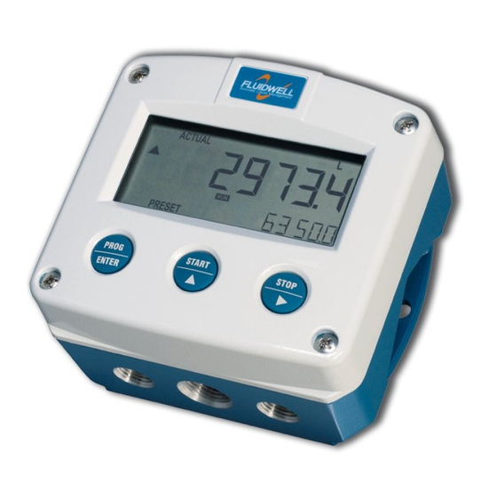
Level monitor with high/low level alarms
Hide thumbs
Also See for F Series:
- Manual (64 pages) ,
- User manual (60 pages) ,
- Operation manual (60 pages)
Table of Contents
Advertisement
Quick Links
Advertisement
Table of Contents

Related Manuals for Fluidwell F Series


Summary of Contents for Fluidwell F Series
- Page 1 F073-T LEVEL MONITOR WITH HIGH / LOW LEVEL ALARMS Signal input sensor: resistance array Alarm output: one level alarm Options: Intrinsically Safe F-Series - Field mounted indicators for safe and hazardous areas. More info: www.fluidwell.com/fseries...
-
Page 2: Safety Instructions
115-230V AC power-supply type PM. The green / yellow wire between the back-casing and removable terminal-block may never be removed. Intrinsically Safe applications: follow the instructions as mentioned in Chapter 5 and consult “Fluidwell F0..-..-XI - Documentation for Intrinsic Safety”. DISPOSAL ... -
Page 3: About The Operation Manual
Manual HF073TEN_v0403_05 Atex_IECEx_CSA_FM © Copyright 2010 Fluidwell bv - The Netherlands. Information in this manual is subject to change without prior notice. The manufacturer is not responsible for mistakes in this material or for incidental damage caused as a direct or indirect result of the delivery, performance or use of this material. -
Page 4: Table Of Contents
Page 4 CONTENTS MANUAL Safety instructions ............................2 Disposal ..............................2 Safety rules and precautionary measures ....................... 2 About the operation manual ..........................3 Contents manual .............................. 4 Introduction ..........................5 1.1. System description of the F073-T ..................5 Operational ..........................6 2.1. -
Page 5: Introduction
Page 5 INTRODUCTION 1.1. SYSTEM DESCRIPTION OF THE F073-T Functions and features The level monitor model F073-T is a microprocessor driven instrument designed to display level, percentage or the height as well as the monitoring of the level for high / low values. This product has been designed with a focus on: ... -
Page 6: Operational
Page 6 OPERATIONAL 2.1. GENERAL The F073-T may only be operated by personnel who are authorized and trained by the operator of the facility. All instructions in this manual are to be observed. Take careful notice of the " Safety rules, instructions and precautionary measures " in the front of this manual. -
Page 7: Operator Information And Functions
Page 7 2.3. OPERATOR INFORMATION AND FUNCTIONS In general, the F073-T will always act at Operator level. The information displayed is dependent upon the SETUP-settings. The signal generated by the connected sensor is measured by the F073-T in the background, whichever screen refresh rate setting is chosen. After pressing a key, the display will be updated quickly during a 30 second period, after which the update frequency will slow-down again. -
Page 8: Operator Alarms
Page 8 2.4. OPERATOR ALARMS Level alarm When the actual level is outside the allowed range, an alarm message will be displayed indicating the type of alarm: LO LEVEL, HI LEVEL. The alarm is terminated automatically as soon as the level is within its range again. ... -
Page 9: Configuration
Page 9 CONFIGURATION 3.1. INTRODUCTION This and the following chapters are exclusively meant for electricians and non-operators. In these, an extensive description of all software settings and hardware connections are provided. Mounting, electrical installation, start-up and maintenance of the instrument may only be carried out by trained personnel authorized by the operator of the facility. - Page 10 Page 10 Matrix structure SETUP-level: SCROLLING THROUGH SETUP-LEVEL Selection of function-group and function: SETUP is divided into several function groups and functions. Each function has a unique number, which is displayed below the word at the bottom of the SETUP display.
- Page 11 Page 11 To change or select a value: To change a value, use to select the digits and to increase that value. If the new value is invalid, the increase sign or decrease-sign will be displayed while you are programming.
-
Page 12: Overview Functions Setup Level
Page 12 3.2.2. OVERVIEW FUNCTIONS SETUP LEVEL SETUP FUNCTIONS AND VARIABLES LEVEL UNIT L - m3 - kg - lb - GAL - USGAL - bbl - no unit DECIMALS 0 - 1 - 2 - 3 (Ref: displayed value) SPAN 0.001 to 999,999 unit OFFSET... -
Page 13: Explanation Of Setup-Functions
Page 13 3.2.3. EXPLANATION OF SETUP-FUNCTIONS 1 - LEVEL 11 determines the measurement unit for the displayed level MEASUREMENT UNIT SETUP (volume) and alarm values. The following units can be selected: L - m3 - kg - lb. - GAL - USGAL - bbl - _ (no unit). Alteration of the measurement unit will have consequences for operator and SETUP-level values. -
Page 14: Height
Page 14 2 - HEIGHT If desired the height of the level column can be calculated and displayed. 21 determines the measurement unit for height. MEASUREMENT UNIT SETUP The following units can be selected: mm - cm - m - mtr - inch - ft - mmwk - mmwc - cmwk – cmwc - mwk - mwc - inwc - ftwc - mbar - bar - psi - no unit. -
Page 15: Display
Page 15 4 - DISPLAY The small 8mm digits can be set to display: UNDER height - percentage - off This function determines if the level alarm values can be set at both SET ALARM Operator level and SETUP-level or SETUP-level only. If SETUP has been selected, the alarm values are still visible for the Operator but cannot be changed. -
Page 16: Sensor
Page 16 6 - SENSOR The resistive signal of a sensor mirrors the actual level. This signal is FILTER measured several times a second by the F073-T. The value measured is a "snap-shot" of the real level as it will be fluctuating. With the help of this digital filter a stable and accurate reading can be obtained while the filter level can be set to a desired value. -
Page 17: Others
Page 17 6 - SENSOR (CONTINUED) With this setting it is possible to calibrate the input value for 100% as the CALIBR. HIGH / 100% signal from the sensor might not reflect it’s reference value at maximum level. This function will measure the provided resistance value at maximum level. -
Page 18: Installation
Page 18 INSTALLATION 4.1. GENERAL DIRECTIONS Mounting, electrical installation, start-up and maintenance of this instrument may only be carried out by trained personnel authorized by the operator of the facility. Personnel must read and understand this Operating Manual before carrying out its instructions. ... -
Page 19: Dimensions- Enclosure
Page 19 4.3. DIMENSIONS- ENCLOSURE Aluminum enclosures: 75 mm (2.95") 112 mm (4.40") 130 mm (5.12") 12mm 12mm 30mm 30mm 24mm 24mm M20 x 1,5 6 x M12 36mm 36mm 30mm 30mm M16 x 1,5 M16 x 1,5 1/2"NPT M20 x 1,5 0.12"... - Page 20 Page 20 GRP enclosures: 75 mm (2.95") 112 mm (4.40") 130 mm (5.12") HK back box: (flat bottom) 75 mm (2.95") 118 mm (4.65”) 25mm 25mm D=20mm D=20mm 12mm 12mm 30mm 30mm 24mm 24mm D=12mm D=16mm D=16mm D=20mm 36mm 36mm 0.12”...
-
Page 21: Installing The Hardware
Page 21 4.4. INSTALLING THE HARDWARE 4.4.1. INTRODUCTION Electro static discharge does inflict irreparable damage to electronics! Before installing or opening the unit, the installer has to discharge himself by touching a well-grounded object. This unit must be installed in accordance with the EMC guidelines (Electro Magnetic Compatibility). -
Page 22: Terminal Connectors With Power Supply - Type : Pb / Pd / Px
Page 22 4.4.2. TERMINAL CONNECTORS WITH POWER SUPPLY - TYPE : PB / PD / PX For Intrinsically Safe applications: read chapter 5. The following terminal connectors are available: ALARM SENSOR SIGNAL POWER SUPPLY POWER SUPPLY RESISTANCE INPUT UNIT OUTPUT BACKLIGHT TYPE: T TYPE: PX... -
Page 23: Terminal Connectors With Power Supply - Type : Pf / Pm
Page 23 Terminal 5-6: POWER SUPPLY UNIT - type PX: To power the unit an internal battery can be used (type PB) and / or an external DC power supply of 8-30V DC (type PX). Connect the "-" to terminal 5 and the "+" to terminal 6. When power is applied to these terminals, the optional internal battery will be disabled / enabled automatically to extend the battery life time. -
Page 24: Intrinsically Safe Applications
Safety Instructions Certificates, safety values, control drawing and declaration of compliance can be found in the document named: “Fluidwell F0..-T-XI - Documentation for Intrinsic Safety”. For installation under ATEX directive: this intrinsically safe device must be installed in accordance with the Atex directive 94/9/EC and the product certificate KEMA 05ATEX1168 X. - Page 25 Page 25 Label information resistive array input type - F0..T-XI (inside and outside the enclosure) Fig. 11: Label information Intrinsically Safe application. HF073TEN_v0403_05 Atex_IECEx_CSA_FM...
-
Page 26: Terminal Connectors Intrinsically Safe Applications
Page 26 5.2. TERMINAL CONNECTORS INTRINSICALLY SAFE APPLICATIONS Terminal connectors F073-T-(PC / PX)-OT-XI-(ZB): SENSOR SIGNAL POWER SUPPLY ALARM POWER SUPPLY RESISTANCE INPUT UNIT OUTPUT BACKLIGHT TYPE: OT OPTION: ZB TYPE: T TYPE: PX Fig. 12: Overview terminal connectors XI - Intrinsically Safe applications. Remarks power supply options: Type PC: offers –... -
Page 27: Battery Replacement Instructions
Page 27 5.4. BATTERY REPLACEMENT INSTRUCTIONS FW-LiBAT-001 - INST001 Fig. 14: Battery replacement instructions Intrinsically Safe Battery. HF073TEN_v0403_05 Atex_IECEx_CSA_FM... -
Page 28: Maintenance
Page 28 MAINTENANCE 6.1. GENERAL DIRECTIONS Mounting, electrical installation, start-up and maintenance of the instrument may only be carried out by trained personnel authorized by the operator of the facility. Personnel must read and understand this Operating Manual before carrying out its instructions. ... -
Page 29: Appendix A: Technical Specification
Page 29 APPENDIX A: TECHNICAL SPECIFICATION GENERAL Display Type High intensity reflective numeric and alphanumeric LCD, UV-resistant. Digits Seven 17mm (0.67") and eleven 8mm (0.31"). Various symbols and measuring units. Refresh rate User definable: 8 times/sec - 30 secs. Type ZB (option) Tri-color configurable LED-backlight - green, amber with red flashing during alarm. - Page 30 Page 30 Sensor excitation Type PB / PC / PX Sensor supply not available. Type PD As connected power supply voltage (internally linked) Terminal connections Type: Removable plug-in terminal strip. Wire max. 1.5mm2 and 2.5mm2 Data protection Type EEPROM backup of all setting. Data retention at least 10 years. Pass code Configuration settings can be pass code protected.
- Page 31 Page 31 OPERATIONAL Operator functions Displayed functions • level. • height or percentage (or no indication). • alarm value’s low - high level. • alarm value’s can be entered (this function can be disabled). Level Digits 6 digits. Units L, m3, GAL, USGAL, KG, lb, bbl, no unit. Decimals 0 - 1 - 2 or 3.
-
Page 32: Appendix B: Troubleshooting
Page 32 APPENDIX B: TROUBLESHOOTING In this appendix, several problems are included that can occur when the F073-T is going to be installed or while it is in operation. Level displays "0 / zero" while a higher signal is available: Check: ... -
Page 33: Index Of This Manual
Page 33 INDEX OF THIS MANUAL actual settings level alarm 8, 32 alarm alarm output function decimals 13, 14 alarm values enter alarm value delay time alarm measuring unit 13, 14 display level zero Span set alarm operator level Span alarm values low current backlight... -
Page 34: List Of Figures In This Manual
Page 34 LIST OF FIGURES IN THIS MANUAL Fig. 1: Typical application for the F073-T with reed chain ..............5 Fig. 2: Control Panel..........................6 Fig. 3: Example of display information during process................. 7 Fig. 4: Example of display information during programming minimum level........7 Fig. -
Page 35: Notes
Page 35 NOTES LIST OF CONFIGURATION SETTINGS SETTING DEFAULT DATE: DATE: 1 - LEVEL Enter your settings here 11 unit 12 decimals 000000 13 span 000001 L 14 offset 000000 L 2 - HEIGHT 21 unit 22 decimals 000000 23 span 000001 m 24 offset 000000 m... - Page 36 74 pass code 0000 75 tagnumber 0000000 Fluidwell bv HF073TEN_v0403_05 Atex_IECEx_CSA_FM PO box 6 Voltaweg 23 Website: www.fluidwell.com 5460 AA Veghel 5466 AZ Veghel Find your nearest representative: www.fluidwell.com/representatives The Netherlands The Netherlands Copyright Fluidwell bv - 2012 - HF110AEN_v0501_03...
Need help?
Do you have a question about the F Series and is the answer not in the manual?
Questions and answers