Fluidwell F Series Manual
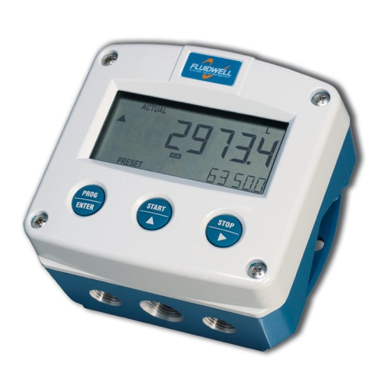
Dual flow rate indicator / totalizer
Hide thumbs
Also See for F Series:
- Manual (64 pages) ,
- User manual (60 pages) ,
- Operation manual (60 pages)
Table of Contents
Advertisement
Quick Links
Advertisement
Table of Contents

Subscribe to Our Youtube Channel
Related Manuals for Fluidwell F Series


Summary of Contents for Fluidwell F Series
- Page 1 F111-P DUAL FLOW RATE INDICATOR / TOTALIZER Signal input flowmeter: pulse, Namur and coil Signal outputs: two pulse outputs ref. total Options: Intrinsically safe, Modbus communication F-Series - Field mounted indicators for safe and hazardous areas. More info: www.fluidwell.com/fseries...
-
Page 2: Safety Instructions
Page 2 SAFETY INSTRUCTIONS • Any responsibility is lapsed if the instructions and procedures as described in this manual are not followed. • LIFE SUPPORT APPLICATIONS: The F111-P is not designed for use in life support appliances, devices, or systems where malfunction of the product can reasonably be expected to result in a personal injury. -
Page 3: About The Manual
: 03.04.xx Manual : FW_F111-P_M_v2201-02_EN.docx © Copyright 2024 : Fluidwell B.V. - the Netherlands Information in this manual is subject to change without prior notice. The manufacturer is not responsible for mistakes in this material or for incidental damage caused as a direct or indirect result of the delivery, performance or use of this material. -
Page 4: Table Of Contents
Page 4 TABLE OF CONTENTS SAFETY INSTRUCTIONS........................2 DISPOSAL OF ELECTRONIC WASTE ....................2 SAFETY RULES AND PRECAUTIONARY MEASURES ..............2 ABOUT THE MANUAL ........................3 WARRANTY AND TECHNICAL SUPPORT ..................3 TABLE OF CONTENTS ........................4 INTRODUCTION ........................6 System description ...................... - Page 5 Page 5 5.2.1 General information and instructions ..............33 5.2.2 Installations based on ATEX or IECEx certificate ..........34 Electrical data – Annex 1 ..................35 5.2.3 5.2.4 Power supply wiring .................... 37 5.2.5 Sensor supply ..................... 37 Terminal connectors Intrinsically Safe applications – Type XI ........38 5.3.1 Terminal 26-29: Type CT - Communication ............
-
Page 6: Introduction
Page 6 1 INTRODUCTION SYSTEM DESCRIPTION Functions and features The dual flow rate / totalizer model F111-P is a microprocessor driven instrument designed to show the flow rate, the total and the accumulated total of two completely separated flow measurement systems. - Page 7 Page 7 Configuration of the unit The F111-P is designed for use in many types of applications. For that reason, a setup menu is available to program the F111-P according to your specific requirements. The setup includes several important features, such as K-Factors, engineering units, signal selection, power management (to extend battery life-time), etc.
-
Page 8: Operational
Page 8 2 OPERATIONAL GENERAL INFORMATION This chapter describes the daily use of the F111-P. This instruction is meant for users / operators. • This device may only be operated by persons who are authorized and trained by the operator of the facility. All instructions in this manual are to be observed. •... - Page 9 Page 9 ▪ Clear total The value for total can be reset. To do so, press the CLEAR/ key twice. When the key is pressed once, the text "PUSH CLEAR" is shown. To avoid a reset at this stage, press another key other than the CLEAR/...
-
Page 10: Configuration
Page 10 3 CONFIGURATION INTRODUCTION This and the following chapters are exclusively meant for electricians and non-operators. In these, an extensive description of all software settings and hardware connections are provided. • Mounting, electrical installation, start-up and maintenance of this device may only be carried out by trained persons authorized by the operator of the facility. -
Page 11: Programming Sequence
Page 11 Use the control panel to navigate through SETUP-level PROG-key When a function is selected, this key is used to start the programming sequence. When only a function group is selected (and no function), this key is used to scroll back a function group (e.g. -
Page 12: Returning To Operator-Level
Page 12 3.2.4 RETURNING TO OPERATOR-LEVEL When all settings are configured correctly, the unit can be returned to OPERATE-level. Please keep a record of all settings for later reference. Use the control panel to return to OPERATE-level PROG-key In order to return to the operator level, press the PROG-key for three seconds. When no keys are pressed for 2 minutes, SETUP-level will be left automatically. -
Page 13: Menu 1 - Total A
Page 13 COMMUNICATION SPEED 1200; 2400; 4800; 9600; 9600HP; 19200; 38400 ADDRESS 1 - 247 MODE rtu; asc; off DATABITS 8 bits, 7 bits PARITY none, even, odd OTHERS MODEL F111-P SOFTWARE VERSION nn:nn:nn SERIAL NO. nnnnnnn PASSWORD 0000 - 9999 TAG-NR 0000000 - 9999999 MENU 1 –... -
Page 14: Menu 3 - Total B
Page 14 TIME This setting is used to set the time unit for the flow rate A calculation. Note that the flow rate is given in engineering unit/time unit, e.g. liters/minute (l/min). When you change this setting, also recalculate and change the settings for the analog rate-min and analog rate-max. -
Page 15: Menu 6 - Power Management
Page 15 3.3.7 MENU 6 - POWER MANAGEMENT When used with the internal battery option (type PB/PC), the user can expect reliable measurement over a long period of time. The F111-P has several smart power management functions to extend the battery life time significantly. Two of these functions can be set. POWER MANAGEMENT LCD NEW The calculation of the display-information influences the power... -
Page 16: Menu 8 - Pulse Output A
Page 16 3.3.9 MENU 8 - PULSE OUTPUT A For each flowmeter input A and B, one transistor or mechanic relay output is available as a scaled pulse output according to the accumulated total. PULSE OUTPUT WIDTH The pulse width determines the time that the output will be active; in other words the pulse duration. -
Page 17: Installation
Page 17 4 INSTALLATION GENERAL DIRECTIONS • Mounting, electrical installation, start-up and maintenance of this device may only be carried out by trained persons authorized by the operator of the facility. Persons must read and understand this manual before carrying out its instructions. •... -
Page 18: Handling The F-Series Enclosure
Page 18 HANDLING THE F-SERIES ENCLOSURE 4.3.1 IDENTIFICATION The F1-Series can be supplied as suitable for Safe Area or Hazardous Area. Suitability for Intrinsic Safety is indicated in the model code by Type XI (e.g. F111-P-XI). For Intrinsically Safe applications: Installation and identification labels are shown in chapter 5. Identification label To identify your F1-Series device, all field mount enclosures have a weatherproof identification label placed on the outside of the unit. -
Page 19: Opening / Removing The Cover
Page 19 Terminal label Also on the inside, a terminal label is placed to indicate the location of the terminals and settings for the sensor supply configuration switches. Fig. 8: Identification – Example of F1-Series terminal label (safe area) Serial number and year of production The serial number can be reviewed on the identification label or in SETUP-menu Others. -
Page 20: Mechanical Installation
Page 20 MECHANICAL INSTALLATION DIMENSIONS – ALUMINUM AND STAINLESS STEEL ENCLOSURES 4.4.1 Fig. 9: Dimensions – Aluminum and stainless steel enclosures FW_F111-P_M_v2201-02_EN.docx... -
Page 21: Dimensions - Non-Metallic Enclosures
Page 21 DIMENSIONS – NON-METALLIC ENCLOSURES 4.4.2 Fig. 10: Dimensions – Non-metallic enclosures FW_F111-P_M_v2201-02_EN.docx... -
Page 22: Mounting
Page 22 4.4.3 MOUNTING The enclosure can be installed by itself or with the aid of a mounting plate in the configurations shown below. When the unit is installed on a wall or onto a meter, please use components and installation techniques that are suitable for the used materials. -
Page 23: Electrical Installation
Page 23 ELECTRICAL INSTALLATION • Electro static discharge does inflict irreparable damage to electronics! Before installing or opening the F111-P, the installer has to discharge himself by touching a well-grounded object. • For reasons of ESD and safety, always ground the metal enclosure properly as indicated, especially if the unit has been supplied with the 115-230V AC power-supply type PM or relays type OR. -
Page 24: Field Wiring Connections
Inside of the Fluidwell unit, the various common ground terminals are connected to each other. It is advised to terminate the wire screens in the vicinity of the sensor and to insulate the wire screen with a shrink tube at the F111-P side. -
Page 25: Sensor Supply
Page 25 4.5.5 SENSOR SUPPLY For type PB / PX – Terminal 11 and 14: Limited sensor supply These types of power supply only offer a limited sensor supply, which SHOULD NOT be used to supply the flowmeters electronics, converters etc. as it will not provide adequate sustained power! All energy used by the flowmeters pick-up will directly influence the battery life-time. -
Page 26: Terminal Connectors Safe Area Applications - Type Xx / Xf
Page 26 TERMINAL CONNECTORS SAFE AREA APPLICATIONS – TYPE XX / XF Take careful notice of all safety and precautionary measures indicated in paragraph 4.5: Electrical Installation and review paragraph 4.5.3 and 4.5.4 before applying any field or power supply wiring. For Intrinsically Safe applications (Type XI): read chapter 5. -
Page 27: Terminal 03-04: Scaled Pulse Output (Flow B)
Page 27 4.6.2 TERMINAL 03-04: SCALED PULSE OUTPUT (FLOW B) Setup 9 determines the pulse output function for input B. The maximum pulse frequency of this output is 500Hz. If a relay output option has been supplied, be sure that the output frequency does not exceed 5Hz or else the life-time of the relay will be reduced significantly. -
Page 28: Terminal 09-11: Flowmeter A Input
Page 28 Type OT Two passive transistor outputs are available with this option. Max. driving capacity 300mA@50V Fig. 16: Terminal connections - Transistor output (typical) 4.6.4 TERMINAL 09-11: FLOWMETER A INPUT Three basic types of flowmeter signals can be connected to the unit: pulse, active pulse or sine- wave (coil). - Page 29 Page 29 Pulse-signal NPN / NPN-LP The F111-P is suitable for use with flowmeters which have a NPN output signal. For reliable pulse detection, the pulse amplitude has to go below 1.2V. Signal setting NPN-LP employs a low-pass signal noise filter, which limits the maximum input frequency (read chapter 3). Fig.
-
Page 30: Terminal 12-14: Flowmeter B Input
Page 30 Reed-switch The F111-P is suitable for use with flowmeters which have a reed-switch. To avoid pulse bounce from the reed-switch, it is advised to select REED LP – low-pass filter (read chapter 3). Fig. 21: Terminal connections - Reed-switch signal input (typical) NAMUR-signal The F111-P is suitable for flowmeters with an Namur signal. -
Page 31: Terminal 26-31: Type Cb / Ch / Ci - Communication (Option)
Page 31 4.6.6 TERMINAL 26-31: TYPE CB / CH / CI - COMMUNICATION (OPTION) Serial communications on hardware layers RS232, RS485 and TTL (intrinsic safety) are possible. Make sure that the hardware layer specific requirements are met to achieve reliable communication and read the Modbus communication protocol and Appendix C. -
Page 32: Intrinsically Safe Applications
Page 32 5 INTRINSICALLY SAFE APPLICATIONS IDENTIFICATION The F1-Series can be supplied as suitable for Safe Area or Hazardous Area. Suitability for Intrinsic Safety is indicated in the model code by Type XI (e.g. F111-P-XI). If Type XI is not indicated your device is not suitable for Intrinsically Safe applications! Identification label To identify your F1-Series device, all field mount enclosures have a weatherproof identification label placed on the outside of the unit. -
Page 33: Electrical Installation In Hazardous Area
Page 33 Terminal label Also on the inside, a terminal label is placed to indicate the location of the terminals and settings for the sensor supply configuration switches. Fig. 26: Identification – Example of F1-Series terminal label (intrinsic safety) ELECTRICAL INSTALLATION IN HAZARDOUS AREA 5.2.1 GENERAL INFORMATION AND INSTRUCTIONS Cautions... -
Page 34: Installations Based On Atex Or Iecex Certificate
Page 34 5.2.2 INSTALLATIONS BASED ON ATEX OR IECEX CERTIFICATE Installation instructions • For installation under ATEX directive: this Intrinsically Safe device must be installed in accordance with ATEX directive 2014/34/EU and product certificate KEMA 03ATEX1074 X. • For installation under IECEx scheme: this Intrinsically Safe device must be installed in accordance with product certificate IECEx DEK 11.0042X. -
Page 35: Electrical Data - Annex 1
Page 35 ELECTRICAL DATA – ANNEX 1 5.2.3 Annex 1 (model specific) to type XI product certificates KEMA 03ATEX1074 X, IECEx DEK 11.0042X For the combined connection of the different supply, input and output circuits, the installation instructions of the manufacturer shall be observed. From the safety point of view the circuits shall be considered to be connected to earth. - Page 36 Page 36 Coil, Switch, PNP, NAMUR In type of protection intrinsic safey Ex ia IIB/IIIC or Ex ia IIC, in combination inputs with connected external supply input type -PD, with following maximum values: (terminals 10 and 11, 8.7 V Ex ia IIB/IIIC Ex ia IIC terminals 13 and 14) 25 mA...
-
Page 37: Power Supply Wiring
Page 37 5.2.4 POWER SUPPLY WIRING The F111-P can be powered from an external power supply. An internal power supply is also available in the form of a lithium battery. When both external and internal power supplies are present, the internal power supply is interrupted and will act as a backup supply. Note that the optional backlight only works with external power. -
Page 38: Terminal Connectors Intrinsically Safe Applications - Type Xi
Page 38 TERMINAL CONNECTORS INTRINSICALLY SAFE APPLICATIONS – TYPE XI Take careful notice of all safety and precautionary measures indicated in paragraph 5.2: Electrical installation in hazardous area and review paragraph 5.2.4 and 5.2.5 before applying any field or power supply wiring. Chapter 4 shows general information regarding the electrical installation of the F111-P. -
Page 39: Configuration Examples Intrinsically Safe Applications
Page 39 CONFIGURATION EXAMPLES INTRINSICALLY SAFE APPLICATIONS Fig. 29: F111-P-(CT)-(OT)-PC-(PX)-XI - Battery powered - IIB/IIC – IIIC FW_F111-P_M_v2201-02_EN.docx... - Page 40 Page 40 Fig. 30: F111-P-CT-OT-PX-XI - IIB/IIC - IIIC FW_F111-P_M_v2201-02_EN.docx...
-
Page 41: Maintenance
Repairs should only be carried out by the manufacturer or his authorized agent. Repair policy If you have any problem with your Fluidwell product and you wish to repair it, please follow the procedure below: a. Obtain a Return Material Authorization (RMA) from your supplier or distributor Together with the RMA, you need to complete a repair form to submit detailed information about the problem. -
Page 42: Battery Replacement Instructions
Page 42 BATTERY REPLACEMENT INSTRUCTIONS 6.3.1 SAFETY INSTRUCTIONS • Handle the battery with the utmost care to prevent a short circuit and damage. A mistreated battery can become unsafe. Unsafe batteries can cause (serious) injury to persons. Do not recharge, crush, disassemble, incinerate, heat above its rated temperature or expose contents to water. -
Page 43: Replace The Battery
Page 43 6.3.2 REPLACE THE BATTERY Before starting the battery replacement procedure, make sure that the marking on the new battery corresponds with the type of installation, as shown in paragraph 6.3.1. Remove the old battery as follows: 1. Open the enclosure as indicated in section 4.3 and carefully remove the cable-connectors. 2. -
Page 44: Appendix A Technical Specification
Page 44 APPENDIX A TECHNICAL SPECIFICATION General Display Type High intensity numeric and alphanumeric LCD, UV-resistant. Digits Seven 17mm (0.67") and eleven 8mm (0.31"). Various symbols and measuring units. Refresh rate User definable: 8 times/sec - 30 secs. Type ZB LCD with LED backlight. - Page 45 Page 45 Power supply Type PB Standard lithium battery - life-time depends upon settings - up to 5 years. SAFE AREA ONLY Type PC Intrinsically Safe lithium battery - life-time depends upon settings - up to 5 years. Type PD 8-24V AC / 8-30V DC;...
- Page 46 Page 46 Inputs Flowmeter Type P npn; npn-lp; reed; reed-lp; pnp; pnp-lp; namur; coil-hi; coil-lo; 8-1 DC; 12 DC; 24 DC Frequency Minimum 0 Hz - maximum 7 kHz for total and flow rate. Maximum frequency depends on signal type and internal low-pass filter. E.g.
-
Page 47: Appendix Bproblem Solving
Page 47 APPENDIX B PROBLEM SOLVING In this appendix, several problems are included that can occur when the F111-P is going to be installed or while it is in operation. Flowmeter does not generate pulses: Check: ▪ Signal selection; ▪ Pulse amplitude;... -
Page 48: Appendix C Communication Variables
Page 48 APPENDIX C COMMUNICATION VARIABLES General The product is fitted with the Modbus communication protocol and can be equipped with various physical interfaces like RS485 and RS232 (please see device datasheet for available options). The tables below show the various variables that can be accessed through the communication. Currently, the function codes supported are: •... - Page 49 Page 49 * Clearing total: It is possible to clear the total counter by means of writing a value of 0 to all the 3 registers of total/flow rate in a single write action. Writing any other value will result in the reply of an error message because the registers of total/flow rate are during operation read-only.
- Page 50 Page 50 [d] 232 40233 cut-off time uint16 1...9999 [h] 0x0E8 Representation: 0.1 – 999.9 sec REGISTER VARIABLE TYPE VALUE / REMARKS ADDRESS DISPLAY REGISTERS [d] 64 40065 display function uint16 0=total 1=flow rate [h] 0x040 [d] 65 40066 accumulated total uint16 0=disable 1=enable [h] 0x041...
- Page 51 Page 51 REGISTER TYPE VALUE / REMARKS VARIABLE ADDRESS OTHERS REGISTERS [d] 173 40174 model number uint16 0…9999 [h] 0x0AD [d] 160 40161 model suffix char Representation: ASCII character [h] 0x0A0 [d] 162 40163 firmware version uint32 0…999999 [h] 0x0A2 Representation: nn:nn:nn [d] 165 40166...
-
Page 52: Appendix Ddeclaration Of Conformity
February e, Fluidwell , declare under our sole responsibility that the F eries indicators are designed and will operate conform the following applicable uropean Directives and Harmonised tandards, when installed and operated according to the related manuals:... -
Page 53: Index Of This Manual
Page 53 INDEX OF THIS MANUAL accumulated Total ......... 9 Installation ........... 17 actual settings ..........55 Intrinsic safety ......... 33, 38, 43 Alarm ............. 9 keys ..............8 backlight Low-battery alarm ...........9 density ............14 main-function ..........10 battery life time ..........41 maintenance .......... -
Page 54: List Of Figures In This Manual
Page 54 LIST OF FIGURES IN THIS MANUAL Fig. 1: Typical application ........................6 Fig. 2: Control panel..........................8 Fig. 3: Example of display information during process................. 8 Fig. 4: Example of low-battery alarm....................9 Fig. 5: SETUP matrix structure ......................10 Fig. - Page 55 Page 55 LIST OF CONFIGURATION SETTINGS SETTING DEFAULT DATE : DATE : 1 – TOTAL-A Enter your settings here 1.1 unit 1.2 decimals 0000000 1.3 K-Factor 0000001 1.4 decimals K-Factor 2 - FLOW RATE 2.1 unit 2.2 time /min 2.3 decimals 0000000 2.4 K-Factor 0000001...
- Page 56 B.3 serial no. nnnnnnn B.4 password 0000 B.5 tag-nr 0000000 Fluidwell B.V. PO box 6 Voltaweg 23 Website: www.fluidwell.com 5460 AA Veghel 5466 AZ Veghel Find your nearest representative: www.fluidwell.com/representatives The Netherlands The Netherlands Fluidwell bv - © 2024 - FW_F111-P_M_v2201-02_EN.docx...
Need help?
Do you have a question about the F Series and is the answer not in the manual?
Questions and answers