Table of Contents
Advertisement
Quick Links
Advertisement
Table of Contents

Related Manuals for Advantech BB-MESP211T


Summary of Contents for Advantech BB-MESP211T
- Page 1 Compact Modbus Gateway Model BB-MESP211T USER MANUAL...
- Page 2 Modbus Gateway – BB-MESP211T Advantech B+B SmartWorx - Americas 707 Dayton Road Ottawa, IL 61350 USA Phone (815) 433-5100 Fax (815) 433-5105 www.advantech.com support@advantech-bb.com Documentation Number: BB-MESP211T_5119m...
- Page 3 Modbus Gateway – BB-MESP211T...
-
Page 4: Table Of Contents
Configuring BB-MESP211T on Network without A DHCP Server ................. 37 Configuring BB-MESP211T via Serial Port (Console Mode) ................. 39 Operational Connections ............................41 Using The BB-MESP211T Modbus Gateway in Direct IP Mode ................41 Initiating a Hardware Reset on BB-MESP211T ......................42 Reloading Factory Defaults ............................42 4. - Page 5 5. Diagnostics ................................45 Testing a Modbus Gateway Connection ........................46 Monitor Function ..............................47 6. Setup Examples ................................ 48 Log into your BB-MESP211T ..........................48 7. Modbus Help ................................52 Modbus ASCII/RTU Basics ............................52 Hints and Tips ................................52 8.
-
Page 6: Fcc Radio Frequency Interference Statement
Communications du Canada. ABOUT THIS MANUAL 2019 Advantech B+B SmartWorx. All rights reserved. Information in this manual is subject to change without notice and does not represent a commitment on the part of Advantech B+B SmartWorx. Advantech B+B SmartWorx assumes no responsibility for errors that may appear in this document. -
Page 7: Introduction
LAN/WAN using Direct IP Mode connections. Model BB-MESP211T features a 10/100BaseTX copper RJ-45 port. The BB-MESP211T is built for industrial environments, featuring an IP30 slim-line, panel mountable case with a DIN rail mounting option. The server requires a 10-30Vdc power source. A 12Vdc wall adapter power supply is included and the preferred method to power the unit. -
Page 8: Bb-Mesp211T Hardware
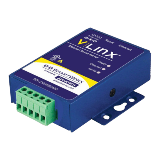
Modbus Gateway – BB-MESP211T 2. BB-MESP211T HARDWARE The BB-MESP211T Modbus Gateway is enclosed in a panel mountable case with a DIN rail mount option and features LED indicators, power, Ethernet and serial connectors and a recessed Reset/Mode switch. PACKAGE CHECKLIST BB-MESP211T Modbus Gateway ships with the following items included: •... -
Page 9: Ethernet Connector
Modbus Gateway is connected to a standard Ethernet network drop using a straight-through RJ45 (male) Ethernet cable. Ethernet Connector. Note: Refer to Appendix D for connection pin-outs. SERIAL PORT CONNECTOR Model BB-MESP211T has a 5-position terminal block connector. Five-Position, Pluggable Terminal Block... -
Page 10: Power Connector
Modbus Gateway – BB-MESP211T POWER CONNECTOR BB-MESP211T serial server uses a barrel jack connector for power. The connector accepts a 2.1 mm plug and requires 12 VDC at 2.5 W maximum. Note: a 12Vdc wall adapter power supply is included. -
Page 11: Setup And Connections
CONNECTING THE POWER SUPPLY Connect a DC power supply to BB-MESP211T Modbus Gateway. A 12V DC, 6W power supply is included with international AC blades. : A 12V DC wall adapter/power supply is included with each serial server and is the preferred method to power the unit. -
Page 12: Connecting The Bb-Mesp211T
If you select RS-232 mode when you configure the Modbus Gateway, you must connect the Modbus serial network to the Modbus Gateway via a serial cable. The BB-MESP211T is a DTE. If the Modbus network is a DTE, use a null modem (cross-over) cable. -
Page 13: Connecting Bb-Mesp211T To A Network
Modbus Gateway are also connected to the network. CONFIGURATION CONNECTIONS The BB-MESP211T Modbus Gateway can be configured over the network or via a serial port. INSTALLING MODBUS GATEWAY MANAGER SOFTWARE 1. The Modbus Gateway Manager Software is contained on the CD that is packaged with the product. - Page 14 (optional) and select if the software will be accessible to your account or anyone who uses the computer. User Information Screen Click “Next.” The Destination Folder Screen will be displayed on your computer. The default directory is: C:\Program Files\Advantech B+B SmartWorx\Vlinx\Modbus Gateway Manager...
- Page 15 Modbus Gateway – BB-MESP211T If desired, you can select another location by pressing the “Browse” button. Destination Folder Screen e. Click “Next.” The Ready to Install Application Screen will be displayed on your computer. You can select the “Back” button to change destination folder.
- Page 16 Modbus Gateway – BB-MESP211T f. Click “Next.” The software will begin installing. Software Installing Screen g. Click “Next.” The Installation Complete screen will be displayed on your computer. Click “Finish” to finish the installation. Installation Complete Screen...
-
Page 17: Configuring The Bb-Mesp211T Via The Network Connection
When configuring via the network, either Modbus Gateway Manager software or the web interface can be used. CONFIGURING THE MODBUS GATEWAY MANAGER The BB-MESP211T Modbus Gateway can be configured over the network with Modbus Gateway Manager software running on a PC. - Page 18 If you do not know the IP address, check the “Network” and “I don’t know the IP address of this device” selections and press the “Connect” button. The software will discover any BB-MESP211T gateways on the network. The configuration manager screen will be displayed on your computer. All available devices will be listed on the top portion of this screen.
- Page 19 Modbus Gateway – BB-MESP211T Configuration Manager Screen 2. All Modbus Gateways on the network will be displayed in the top portion of the screen. To select a gateway, simply click the appropriate device on the top portion of the screen.
-
Page 20: Vlinx Modbus Manager Settings Screen Overview
Modbus Gateway – BB-MESP211T VLINX MODBUS MANAGER SETTINGS SCREEN OVERVIEW Settings Screen Overview This area shows Modbus Gateways available on the network. b. This area is used to jump directly to the configuration screen you need to access. An alternate method of accessing the configuration screens is to use the “Next” button in area C. - Page 21 Modbus Gateway – BB-MESP211T e. This area contains shortcuts to specific functions. 1. “Open” allows you to load a previously saved configuration file into your Modbus Gateway. 2. “Save” allows you to save your configuration to a file. This should not be confused with the “Save”...
-
Page 22: General Settings
Modbus Gateway – BB-MESP211T GENERAL SETTINGS General Settings Screen a. This screen enables you to assign a unique name to the gateway. This allows you to easily identify a particular gateway when multiple devices are used on the same network. - Page 23 Modbus Gateway – BB-MESP211T Changing The Password c. Type your new password in the “Type the new password box.” Verify the password by typing it again in the box provided. To save the new password click the “Save” button. 4. Network Settings To get to the Network Settings Screen you can either click the “Next”...
- Page 24 Modbus Gateway – BB-MESP211T Network Settings Screen (DHCP Selected) b. The default network configuration is to receive an IP address assignment from a DHCP server. DHCP controls whether or not a DHCP server is used to set the IP address, subnet mask and default gateway of the Modbus Gateway.
- Page 25 Modbus Gateway – BB-MESP211T For Class D Network (IP addresses 224.0.0.0 through 239.255.255.255) and Class E Network (IP addresses 240.0.0.0 through 255.255.255.255), the subnet mask is ignored. Default Gateway field contains default route to remote networks. Network Settings Screen (DHCP not Selected) d.
- Page 26 Modbus Gateway – BB-MESP211T Modbus TCP Settings Screen TCP Client Settings 1. Connect to Port identifies TCP port to be used by the Modbus Gateway in TCP client mode. Valid value range is from 1 to 65535. 2. Response Timeout is the maximum amount of time to wait for a response to a request that is sent to the device connected through TCP.
- Page 27 Modbus Gateway – BB-MESP211T You can select “allow specific IP addresses to connect.” This filter is limited to 4 IP addresses. b. You can select “a specific range of IP addresses to connect.” This filter is limited to 4 IP address ranges TCP Connection Filter “Allow Specific IP Addresses to Connect”...
- Page 28 Modbus Gateway – BB-MESP211T TCP Connection Filter “Allow Specific Range of IP Addresses to Connect” 6. Port 1 Settings To access this screen, click the “Next” button or click the Port 1 Serial link on the left side of the screen.
- Page 29 Modbus Gateway – BB-MESP211T Serial Port Screen b. Description - sets the description for this serial port. Maximum length is 32 symbols. Allowed characters are symbols from 'A' to 'Z', from 'a' to 'z', numbers from '0' to '9' and the space.
- Page 30 Modbus Gateway – BB-MESP211T Modbus Port Screen...
- Page 31 Modbus Gateway – BB-MESP211T Modbus Port Screen Advanced b. Attached – This is selectable between Master and Slaves. If Master is selected, the Modbus Gateway will run in TCP server mode; if Slaves is selected, it will run in TCP client mode.
- Page 32 Modbus Gateway – BB-MESP211T Milliseconds TX Delay – This is the minimum amount of time after receiving a response before the next message can be sent out. Valid value range is from 1 to 65535. Save settings by clicking the “Save” button.
- Page 33 Modbus Gateway – BB-MESP211T 9. Modbus ID Routing a. To access this screen click the “Next” button or click the “Modbus ID Routing” Link on the left side of the screen. This screen allows you to set the Modbus Slave ID routing.
- Page 34 Modbus Gateway – BB-MESP211T 10. Modbus Priority a. To access this screen, click the “Next” button or click the “Modbus Priority” link on the left side of the screen. This screen allows you to configure the gateway to move high priority messages to the...
- Page 35 2. In the browser’s address bar, type the IP address of the Modbus Gateway. Type IP Address Note: Your BB-MESP211T Modbus Gateway comes from the factory pre-configured to receive an IP address assignment from a DHCP server. If a DHCP server is not available on your network, it will default to 169.254.102.39.
- Page 36 Modbus Gateway – BB-MESP211T The web interface Login page appears. Modbus Gateway Login Screen 3. The screens for configuring your gateway using a web browser are the same as those used to configure using the Vlinx Modbus Manager software.
-
Page 37: Configuring Bb-Mesp211T On Network Without A Dhcp Server
Modbus Gateway – BB-MESP211T CONFIGURING BB-MESP211T ON NETWORK WITHOUT A DHCP SERVER Your Modbus Gateway comes from the factory set to receive an IP assignment from a DHCP Server. If there is not a DHCP server on your network, the Modbus Gateway will default to IP address 169.254.102.39. If this address does not work with your PC, there are two methods to manually configure the network information. - Page 38 Modbus Gateway – BB-MESP211T b. Use the Vlinx Modbus Manager Software to search for, discover, and configure the Modbus Gateway. 2. Method 2: Change the Modbus Gateway’s network settings to match your PC using Console Mode. (Console mode works in RS-232 only.) Connect a null modem serial cable (crossover cable) from Port 1 on the Modbus Gateway to an available COM port on your PC.
-
Page 39: Configuring Bb-Mesp211T Via Serial Port (Console Mode)
Re-apply power. Open the Vlinx Modbus Manager Software and select “Network” as the method to connect to the device. CONFIGURING BB-MESP211T VIA SERIAL PORT (CONSOLE MODE) Your Modbus Gateway can be configured via a serial port using the Vlinx Modbus Manager software. To use this feature, the Modbus Gateway's serial port must be connected to the serial port of a PC (using a null modem cable, RS-232 only). - Page 40 Modbus Gateway – BB-MESP211T 1. Under Connection, select “Serial Port.” Connection 2. If you do not know which COM port your gateway is connect to, select “Search all serial ports for the device” under Serial Port Options. If you do know, you may specify the COM port by selecting “The device is connected to this serial port”...
-
Page 41: Operational Connections
OPERATIONAL CONNECTIONS USING THE BB-MESP211T MODBUS GATEWAY IN DIRECT IP MODE A Direct IP connection allows applications using TCP/IP socket programs to communicate with COM ports on the Modbus Gateway. In this type of application, the Modbus Gateway is configured as a TCP server. The socket program running on the PC establishes a communication connection with the Modbus Gateway. -
Page 42: Initiating A Hardware Reset On Bb-Mesp211T
Modbus Gateway – BB-MESP211T INITIATING A HARDWARE RESET ON BB-MESP211T To initiate a Hardware Reset on the Modbus Gateway, press and hold the Mode switch for 0 to 2 seconds, and then release it. The LED indicators respond as follows: 1. -
Page 43: Upgrading Firmware
Modbus Gateway – BB-MESP211T 4. UPGRADING FIRMWARE Occasionally, updated firmware may become available for your Modbus Gateway. The firmware can be upgraded using the Vlinx Manager software. The following procedure describes the firmware updating process: 1. Click the Upgrade button to open the Firmware Upgrade dialog box. -
Page 44: Downloading Firmware Files
Modbus Gateway – BB-MESP211T DOWNLOADING FIRMWARE FILES The Firmware File list (second box) displays all firmware files in the firmware installation folder. Only firmware that is compatible with the selected Modbus Gateway is available in this list. To download the latest firmware files from an FTP site on the Internet: 1. -
Page 45: Diagnostics
Modbus Gateway – BB-MESP211T 5. DIAGNOSTICS Clicking the Diagnostics icon opens the Diagnostics dialog box and enables you to check the operation of connected Modbus Gateways on the local computer. The Computer Information box displays information about the type of network connections, the IP addresses, Subnet Masks and Default Gateways in use. -
Page 46: Testing A Modbus Gateway Connection
Modbus Gateway – BB-MESP211T TESTING A MODBUS GATEWAY CONNECTION To run diagnostics on a Modbus Gateway: 1. Click the Diagnostics icon. The Diagnostics dialog box appears. 2. In the drop down box select the specific Modbus Gateway you want to check. -
Page 47: Monitor Function
Modbus Gateway – BB-MESP211T MONITOR FUNCTION The Monitor button displays a screen that shows information about events and data transfer through the Modbus Gateway. To start monitoring, select a Modbus Gateway and press the “Start” button. The “Auto Scroll” check box enables and disables automatic scrolling of the displayed text. -
Page 48: Setup Examples
Modbus Gateway – BB-MESP211T 6. SETUP EXAMPLES The Modbus Gateway can be used to integrate Modbus networks in a wide variety of settings. But,as each setting has its own requirements, users may not understand how a gateway helps, or if it is appropriate for their needs. - Page 49 Modbus Gateway – BB-MESP211T Port 1 Modbus 4. Configure the Port 1 Modbus settings. In this case, Attached should be Slaves, Modbus should be RTU. The other settings depend on your application. 5. Click and access Modbus ID Remapping for each port and configure as necessary.
- Page 50 Modbus Gateway – BB-MESP211T Port 1 Modbus Slave ID Remapping 6. Access Modbus ID Routing. Configure as necessary. In this example, Slave ID 200 is mapped to serial Port 1, Slave ID 1 through 5 and 205 are mapped to serial port 2.
- Page 51 Modbus Gateway – BB-MESP211T 7. Access Modbus Priority and configure as necessary. Modbus Priority...
-
Page 52: Modbus Help
Modbus Gateway – BB-MESP211T 7. MODBUS HELP MODBUS ASCII/RTU BASICS The Modbus protocol emerged in the mid-1970s as an early protocol for linking terminals with Modicon PLCs using a master/slave (sometimes called “master/client”) relationship. This simple, open, message-based protocol caught on quickly and became a de facto standard in the industry. -
Page 53: Appendices
Modbus Gateway – BB-MESP211T 8. APPENDICES This section includes the following Appendices: • Appendix A: Default Gateway Settings • Appendix B: Product Specifications • Appendix C: Dimensional Diagrams • Appendix D: Connector Pinouts APPENDIX A: DEFAULT GATEWAY SETTINGS SETTING DEFAULT VALUE Gateway Name User assigned. -
Page 54: Appendix B: Product Specifications
Modbus Gateway – BB-MESP211T APPENDIX B: PRODUCT SPECIFICATIONS This section includes the following specifications: • General Specifications • Controls, Indicators and Connector Specifications • Serial Interface Specifications • Network Specifications GENERAL SPECIFICATIONS Device BB-MESP211T, Modbus Gateway module Hardware and CD with software for Win XP (32/64 bit), 2003 Server (32/64 bit),... -
Page 55: Controls, Indicators, Connector Specifications
Modbus Gateway – BB-MESP211T CONTROLS, INDICATORS, CONNECTOR SPECIFICATIONS Hold in for 0 to 2 seconds for hardware reset. Hold in for 2 to 10 seconds for Console Mode. (Do a Switches Reset Button hardware reset or recycle power to exit Console Mode.) Hold in for more than 10 seconds to reset to factory defaults. -
Page 56: Network Specifications
Modbus Gateway – BB-MESP211T NETWORK SPECIFICATIONS Memory Serial Memory 8 kB per port Network Memory 4 kB TCP Ports Web Server Modbus client/server port – user configurable 7000 TCP Configuration 10000 Monitor Port UDP Ports 7000 UDP Configuration 8899 Device Discovery... -
Page 57: Appendix C: Dimensional Diagram
Modbus Gateway – BB-MESP211T APPENDIX C: DIMENSIONAL DIAGRAM... -
Page 58: Appendix D: Serial Connector Pinouts
Modbus Gateway – BB-MESP211T APPENDIX D: SERIAL CONNECTOR PINOUTS TERMINAL BLOCK PINOUTS Terminal RS-232 Direction RS-422 RS-485 (RS-232) Output TDA (-) Data A (-) Output TDB (+) Data B (+) Input RDA (-) Input RDB (+) **** In RS-422 mode, TX lines are outputs and RX lines are inputs. Connect the Modbus Gateway TXB(+) line to the RXB(+) line of the Modbus network;... -
Page 59: Advantech B+B Smartworx Technical Support
Modbus Gateway – BB-MESP211T ADVANTECH B+B TECHNICAL SUPPORT Phone: 1 (800) 346-3119 Fax: 1 (815) 433-5109 Email: support@advantech-bb.com Web: www.advantech.com ELECTROSTATIC DISCHARGE PRECAUTIONS Electrostatic discharge (ESD) can cause damage to any product, add-in modules or stand-alone units, containing electronic components. Always observe the following precautions when installing or handling these kinds of products. -
Page 60: Regulatory, Safety, Directives, Standards
Modbus Gateway – BB-MESP211T REGULATORY UL Listed (File E353510) FCC Part 15 Class B 2014/30/EU – Electromagnetic Compatibility Directive (EMC) 2014/35/EU – Low Voltage Directive (LVD) CE - Directives 2015/863/EU – Reduction of Hazardous Substances Directive (RoHS-3) 2012/19/EU – Waste Electrical and Electronic Equipment (WEEE) EN55032 Class B –...
Need help?
Do you have a question about the BB-MESP211T and is the answer not in the manual?
Questions and answers