Table of Contents
Advertisement
Advertisement
Table of Contents

Related Manuals for Advantech ECU-1251 Series


Summary of Contents for Advantech ECU-1251 Series
- Page 1 User Manual ECU-1251 Series...
- Page 2 No part of this manual may be reproduced, copied, translated or transmitted in any form or by any means without the prior written permission of Advantech Co., Ltd. Information provided in this manual is intended to be accurate and reliable. How- ever, Advantech Co., Ltd.
- Page 3 Because of Advantech’s high quality-control standards and rigorous testing, most of our customers never need to use our repair service. If an Advantech product is defec- tive, it will be repaired or replaced at no charge during the warranty period. For out- of-warranty repairs, you will be billed according to the cost of replacement materials, service time and freight.
- Page 4 Technical Support and Assistance Visit the Advantech web site at www.advantech.com/support where you can find the latest information about the product. Contact your distributor, sales representative, or Advantech's customer service center for technical support if you need additional assistance. Please have the following information ready before you call: –...
- Page 5 The sound pressure level at the operator's position according to IEC 704-1:1982 is no more than 70 dB (A). DISCLAIMER: This set of instructions is given according to IEC 704-1. Advantech disclaims all responsibility for the accuracy of any statements contained herein.
- Page 6 ECU-1251 Series User Manual...
-
Page 7: Table Of Contents
Figure 3.9 Vertical DIN-Rail Installation........16 3.3.2 SD&SIM Card Installation ............16 Figure 3.10SD&SIM Card Installation......... 16 3.3.3 Installing a Wireless module Card and Antenna (Optional) ..17 Figure 3.11Installing a Wireless module Card and Antenna..18 ECU-1251 Series User Manual... - Page 8 ECU-1251 Series User Manual viii...
-
Page 9: Chapter 1 Overview
Chapter Overview... -
Page 10: Introduction
Introduction For solar power, electricity and factory related applications which require a total wire- less and Ethernet communication solutions, Advantech has released the ECU-1251 RISC-based industrial communication gateway. ECU-1251 has an open platform design with Cortex A8 processor, up to four RS-232/485 isolated serial ports, two 10/ 100 Ethernet ports and operating temperature range of -40~70°C.WithLinux operat-... -
Page 11: Specifications
Wireless (Optional): Interface: 1x Mini-PCIe (Full-size) Type: WIFI/3G/GPRS/4G Signal: USB 1.2.4 Software OS Support: RT-Linux 3.12 Programming: Linux C 1.2.5 Environment Humidity: 5~95% (non-condensing) Operating Temperature: -40 ~ 70°C Storage Temperature: -40~85°C ECU-1251 Series User Manual... -
Page 12: Safety Precautions
Caution! Always ground yourself to remove any static electric charge before touching ECU-1251 Series. Modern electronic devices are very sensi- tive to static electric charges. Use a grounding wrist strap at all times. Place all electronic components on a static-dissipative surface or in a static-shielded bag. -
Page 13: Chassis Dimensions
Chassis Dimensions: Figure 1.1 ECU-1251 Chassis Dimensions Packing List The accessory package of ECU-1251 contains the following items: (A) ECU-1251 (B) 1 x warranty card (C) Connector ECU-1251 Series User Manual... - Page 14 ECU-1251 Series User Manual...
-
Page 15: Chapter 2 Hardware Functionality
Chapter Hardware Functionality... -
Page 16: Overview
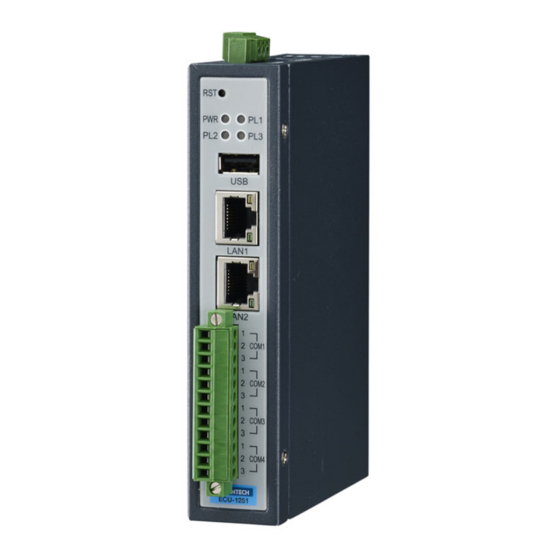
Overview The following figures show the panel configuration on ECU-1251. More information of each peripheral is included in the following sections. Figure 2.1 ECU-1251 overview ECU-1251 Series User Manual... -
Page 17: Led Status Indicators
The LEDs in the front panel can be divided into 4 groups: Figure 2.2 ECU-1251 LED status indicator 2.2.1 System Status Indicators: Status Description Green Power is on Power is off Green Customers can define the Programmable LED state accord- IRIG ing to the actual need. ECU-1251 Series User Manual... -
Page 18: Serial Communication Status Indicator
Blinking, Serial port 4 data being received 2.2.3 Ethernet Status Indicator Color Description Link1 Yellow Lighting, Ethernet not connected Act1 Green Blinking, Ethernet data being transmitted Link2 Yellow Lighting, Ethernet not connected Act2 Green Blinking, Ethernet data being transmitted ECU-1251 Series User Manual... -
Page 19: Chapter 3 Wiring And Installation
Chapter Wiring and Installation... -
Page 20: Wiring
Power Input PWR V+ DC power input PIN PWR V- DC power input PIN 3.1.2 Communication Ports Figure 3.2 RS-232/485 Serial Ports (COM1~ COM4) Table 3.2: RS-232/485 Serial Ports (Pin Assignments) Pins RS-232 RS-485 Data+ Data- ECU-1251 Series User Manual... -
Page 21: Wireless Card Installation
The installation is shown as below. Figure 3.3 USB Connector Table 3.3: USB Connector Pin Assignment Signal DATA- DATA+ Figure 3.4 LAN Connectors (LAN1~LAN4) Table 3.4: LAN Connector Pin Assignments Assignment Description Transmit+ Transmit- Receive+ Not used Receive- ECU-1251 Series User Manual... -
Page 22: Jumper Setting
Jumper Setting The motherboard of ECU-1251 has two types of jumper for user operation, as the below shown. Figure 3.6 Jumper on the back motherboard Table 3.6: Jumper Setting of Terminal Resistor For COM(1?4) Location Description ECU-1251 Series User Manual... -
Page 23: Installation
3.3.1 Wall-mounted and DIN-Rail Installation ECU-1251 supports two types of installation: Wall-mounted and DIN-Rail Installation. For wall-mounted installation, users can fix the device on the wall with 4 screws as shown below. Figure 3.7 Wall-mounted installation ECU-1251 Series User Manual... -
Page 24: Sd&Sim Card Installation
Rail. The detailed steps are shown as below: Figure 3.8 Vertical DIN-Rail buckle Installation Figure 3.9 Vertical DIN-Rail Installation 3.3.2 SD&SIM Card Installation ECU-1251 is equipped with a Micro SD slot and a SIM slot. Figure 3.10 SD&SIM Card Installation ECU-1251 Series User Manual... -
Page 25: Installing A Wireless Module Card And Antenna (Optional)
3.3.3 Installing a Wireless module Card and Antenna (Optional) For optional wireless module card and antenna, please contact Advantech for the fol- lowing wireless solution kit. Top panel with pre-cut antenna holes ECU-1251 Series User Manual... - Page 26 Wireless module card (PCI Express Mini card) The ECU-1251 supports one full-size Mini PCIe slot (only USB signal) for wire- less module card installation. For more information about wireless module cards, refer to the datasheet or contact Advantech. Antenna Select the necessary specification according to your application.
- Page 27 ECU-1251 Series User Manual...
- Page 28 No part of this publication may be reproduced in any form or by any means, electronic, photocopying, recording or otherwise, without prior written permis- sion of the publisher. All brand and product names are trademarks or registered trademarks of their respective companies. © Advantech Co., Ltd. 2017...
Need help?
Do you have a question about the ECU-1251 Series and is the answer not in the manual?
Questions and answers