Table of Contents
Advertisement
Quick Links
Advertisement
Table of Contents

Related Manuals for Advantech Vlinx MESR9 Series


Summary of Contents for Advantech Vlinx MESR9 Series
- Page 1 Vlinx™ Modbus Gateways MESR9xx series USER MANUAL...
- Page 2 MESR9xx Modbus Gateways: Advantech - Americas 707 Dayton Road Ottawa, IL 61350 USA Phone (815) 433-5100 Fax (815) 433-5105 Advantech - European Headquarters Westlink Commercial Park Oranmore, Co. Galway, Ireland Phone +353 91-792444 Fax +353 91-792445 www.advantech.com support@advantech-bb.com Documentation Number: MESR9xx_1119m...
-
Page 3: Table Of Contents
MESR9xx Modbus Gateways: CONTENTS ABOUT THIS DOCUMENT ..................... 6 1. INTRODUCTION ........................7 About MESR9xx Modbus Gateways ..................7 MESR9xx Modbus Gateways – Numbering Matrix ..............8 List of MESR9xx Modbus Gateway Models ................9 MESR9xx Modbus Gateway Features ...................10 Vlinx™... - Page 4 MESR9xx Modbus Gateways: Connecting MESR9xx Modbus Gateways to a Network ............18 Network Connection (10BaseT/100BaseTX) ..............18 Fiber Optic Connection .......................18 MESR9xx Modbus Gateway Configuration Connections ............18 Installing Modbus Configuration Manager Software ............19 Configuring the Gateway via the Network Connection ............23 Configuring with Modbus Configuration Manager ...............23 Configuring the MESR9xx Modbus Gateway on Networks without a DHCP Server ....38 Configuring the MESR9xx Modbus Gateway via the Serial Port (Console Mode) ....41 MESR9xx Modbus Gateway Operational Connections ............43...
- Page 5 Serial Interface Specifications .....................72 Network Specifications .......................72 Appendix C: Dimensional Diagrams ..................73 Appendix D: Connector Pinouts .....................77 MESR901 Serial Port Pinouts .....................77 MESR902T Serial Port Pinouts ...................78 Standard Ethernet Cable RJ45 Pin-out ................79 GLOSSARY ..........................80 APPROVALS, DIRECTIVES, STANDARDS ................81 ADVANTECH TECHNICAL SUPPORT ..................81...
-
Page 6: About This Document
Gateways: ABOUT THIS DOCUMENT © 2019 Advantech No part of this publication may be reproduced or transmitted in any form or by any means, electronic or mechanical, including photography, recording, or any information storage and retrieval system without written consent. Information in this manual is subject to change without notice, and does... -
Page 7: Introduction
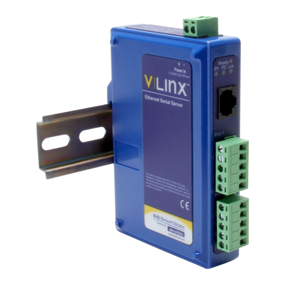
MESR9xx Modbus Gateways: 1. INTRODUCTION Thank you for purchasing a MESR9xx Modbus Gateway product. This product has been manufactured to the highest standards of quality and performance to ensure your complete satisfaction. An MESR921-MT Modbus Gateway ABOUT MESR9xx MODBUS GATEWAYS MESR9xx Modbus Gateways connect Modbus networks (RS-232, RS-422 or RS-485) to Ethernet networks, allowing the Modbus network to become a node on the network. -
Page 8: Mesr9Xx Modbus Gateways - Numbering Matrix
MESR9xx Modbus Gateways: MESR9xx MODBUS GATEWAYS – NUMBERING MATRIX... -
Page 9: List Of Mesr9Xx Modbus Gateway Models
MESR9xx Modbus Gateways: LIST OF MESR9xx MODBUS GATEW AY MODELS The following table lists the available MESR9xx Modbus Gateway model configurations. Model Serial Serial Ethernet Ethernet Ethernet Number Port/s Connector Port/s Media Connector/s MESR901 DB9 or TB Copper (1) RJ-45 MESR902T Copper (1) RJ-45... -
Page 10: Mesr9Xx Modbus Gateway Features
MESR9xx Modbus Gateways: MESR9xx MODBUS GATEWAY FEATURES • Four series: MESR901 (one serial port, one Ethernet Port) • MESR902T (two serial ports with pluggable terminal blocks, one Ethernet port) • MESR921-x (one serial port, two Ethernet Ports) • MESR922T-x (two serial ports with pluggable terminal blocks, two Ethernet Ports) •... -
Page 11: Mesr9Xx Modbus Gateway Hardware
MESR9xx Modbus Gateways: 2. MESR9xx MODBUS GATEWAY HARDWARE PACKAGE CHECKLIST MESR9xx Modbus Gateways are shipped with the following items included: • MESR9xx Modbus Gateway Module • Quick Start Guide • CD with User Manual, Quick Start Guide, Firmware and Configuration Software MESR9xx MODBUS GATEWAY ENCLOSURES &... -
Page 12: Led Indicators
MESR9xx Modbus Gateways: LED INDICATORS MESR9xx Modbus Gateways have three types of LED indicators: Ethernet Link LEDs, Ready LED and Serial Port LEDs. Ready Ethernet Port LEDs on 1 and 2 Ethernet Port Modbus Gateways E1/E2 ETHERNET LINK LED The Ethernet Link LED (E1 or E2) illuminates (green) if the Ethernet is connected. When the LED is blinking, it indicates that there is data traffic on the Ethernet link. -
Page 13: Mode Switch
MESR9xx Modbus Gateways: MODE SWITCH A recessed momentary reset switch is located on the top of the enclosure. To activate the switch, insert a small plastic tool through the hole in the enclosure and press lightly. Mode Switch The Mode switch can be used to: •... -
Page 14: Fiber Optic Connectors
MESR9xx Modbus Gateways: FIBER OPTIC CONNECTORS Modbus gateway models using fiber optic network connections use either SC or ST connectors, depending on the specific model. SC and ST Fiber Optic Cable Connectors SERIAL PORT CONNECTORS MESR9xx Modbus Gateways use four serial port connector configurations, depending on the model: •... -
Page 15: Power Connector
MESR9xx Modbus Gateways: POWER CONNECTOR The power connector is a 2-position pluggable terminal block. Power Connection MOUNTING HARDWARE MESR9xx Modbus Gateway modules can be DIN rail mounted. The DIN mounting clip and spring is included on each module. DIN Clips Detail - large DIN clips are used on MESR92x; small DIN clips on MESR90x. -
Page 16: Modbus Gateway Setup & Connections
MESR9xx Modbus Gateways: 3. MODBUS GATEWAY SETUP & CONNECTIONS NOTE: In this section, devices to be connected to the Modbus gateway’s serial connection are simply referred to as the “Modbus network”. CONNECTING THE POWER SUPPLY Connect a DC power supply to the power terminals on the top of the Modbus gateway. Polarity of the wires is indicated on the label on the side of the Modbus gateway. - Page 17 MESR9xx Modbus Gateways: The MESR9x1-x has one serial connection that supports RS-232, RS-422 and RS-485 (2- and 4-wire). The unit has two connectors: a DB9M connector and a 5-position terminal block. If you select RS-232 mode when you configure the Modbus gateway, you must connect the Modbus serial network to the Modbus gateway via a serial cable.
-
Page 18: Connecting The Mesr9X2T-X
MESR9xx Modbus Gateways: CONNECTING THE MESR9x2T-X The MESR9x2T-xx has two serial connections that support RS-232, RS-422 and RS-485 (2-wire and 4-wire). The unit has two connectors - both are 5-position terminal blocks. Make the appropriate connections to the terminal blocks to match the serial connection mode that you select when configuring the Modbus gateway. -
Page 19: Installing Modbus Configuration Manager Software
MESR9xx Modbus Gateways: INSTALLING MODBUS CONFIGURATION MANAGER SOFTW ARE 1. The Modbus Configuration Manager Software is contained on the CD which is packaged with the product. Insert the CD into your CD ROM drive. The software should automatically begin the installation process. If AUTO RUN is disabled on your computer, open the CD drive and double-click on the executable file. - Page 20 MESR9xx Modbus Gateways: c. Click Next. The User Information Screen will be displayed on your computer. Enter your name and organization (optional) and select if the software will be accessible to your account or anyone who uses the computer. User Information Screen d.
- Page 21 MESR9xx Modbus Gateways: e. Click Next. The Ready to Install Application Screen will be displayed on your computer. You can select the Back button to change destination folder. Ready to Install Application Screen f. Click Next. The software will begin installing. Software Installing Screen...
- Page 22 MESR9xx Modbus Gateways: g. After the installation is complete, an information screen will be displayed containing contact information and release notes. Click Next. Information Screen h. Click Next. The Installation Complete screen will be displayed on your computer. Click Finish to finish the installation. Installation Complete Screen...
-
Page 23: Configuring The Gateway Via The Network Connection
PC. To open Modbus Configuration Manager: 1. From the Desktop, click Start Programs Advantech Vlinx Modbus Gateway Manager. Alternate method: double-click the shortcut installed on the desktop. Opening Vlinx Modbus Gateway Manager... - Page 24 MESR9xx Modbus Gateways: 2. The Vlinx Modbus Configuration Manager Device Discovery window appears. Vlinx Modbus Configuration Manager Discovery Window 3. If you do not know the IP address, check Network and I don’t know the IP address of this device selections and click the Connect” button. The software will discover any MESR9xx Gateways on the network.
- Page 25 MESR9xx Modbus Gateways: 4. All Modbus Gateways on the network will be displayed in the top portion of the screen. To select a gateway, click the appropriate device. a. The main portion of the screen displays the Model, Firmware version, Hardware version, MAC Address, and Link Status.
- Page 26 MESR9xx Modbus Gateways: 3. Search allows you to search for Modbus Gateways on the network. 4. Upgrade allows you to upgrade your Modbus Gateway’s firmware. 5. Diagnostic allows you to test a configured Modbus Gateway. See Section 5. 6. Monitor allows you to monitor a Modbus Gateway. See Section 5. 7.
- Page 27 MESR9xx Modbus Gateways: Changing The Password c. Type your new password in the “Type the new password box.” Verify the password by typing it again in the box provided. To save the new password click the “Save” button.
- Page 28 MESR9xx Modbus Gateways: 8. Network Settings a. To get to the Network Settings Screen, you can either click the Next button or click on the Network link on the left side of the screen. Network Settings Screen (DHCP Selected) b. The default network configuration is to receive an IP address assignment from a DHCP Server.
- Page 29 MESR9xx Modbus Gateways: For Class B network (IP addresses 128.0.0.0 through 191.255.255.255), the default subnet mask is 255.255.0.0. For Class C network (IP addresses 192.0.0.0 through 223.255.255.255), the default subnet mask is 255.255.255.0. For Class D network (IP addresses 224.0.0.0 through 239.255.255.255) and Class E network (IP addresses 240.0.0.0 through 255.255.255.255), the subnet mask is ignored.
- Page 30 MESR9xx Modbus Gateways: Modbus TCP Settings Screen c. TCP Server Settings i. Connect to Port identifies TCP port to be used by the Modbus Gateway in TCP client mode. Valid value range is from 1 to 65535. ii. Response Timeout is the maximum amount of time to wait for a response to a request that is sent to the device connected through TCP.
- Page 31 MESR9xx Modbus Gateways: TCP Connection Filter “Allow Specific IP addresses to Connect a. You can select and allow a specific range of IP addresses to connect. This filter is limited to 4 IP address ranges. b. Save settings by clicking the Save button. TCP Connection Filter “Allow Specific Range of IP Addresses to Connect”...
- Page 32 MESR9xx Modbus Gateways: 10. PORT x Serial Settings a. To access this screen, click the Next button or click the Port X Serial link on the left side of the screen. X = the Serial Port number (1 or 2) b.
- Page 33 MESR9xx Modbus Gateways: 11. Port X Modbus a. To access this screen, click the Next” button or click the Port X Modbus” link on the left side of the screen. X = the Serial Port Number (1 or 2) b. This screen allows you to change Modbus settings for the port. Modbus Port Screen c.
- Page 34 MESR9xx Modbus Gateways: h. Modbus Serial Retires – Select 0 through 5. This sets the maximum number of times that the Modbus gateway will retry to send a Modbus message to a Modbus client, before reporting a 0Bh exception if it is selected. Number of retries is limited to 5.
- Page 35 MESR9xx Modbus Gateways: e. The third box in line is the starting ID of a range to remap to. Valid value range is from 1 to 255. The fourth box in line is auto-filled in based on the range filled in the first 3 boxes. Valid value range is from 1 to 255.
- Page 36 MESR9xx Modbus Gateways: 14. Modbus Priority a. To access this screen, click the Next button or click the Modbus Priority link on the left side of the screen. b. This screen allows you to configure the gateway to move high priority messages to the front of the serial message buffer.
- Page 37 MESR9xx Modbus Gateways: CONFIGURING WITH THE WEB INTERFACE MESR9xx Modbus Gateways can be configured over the network using a standard internet browser such as Internet Explorer or Firefox. To open the web configuration interface: 1. On a PC connected to the network, open a web browser. Open Web Browser 2.
-
Page 38: Configuring The Mesr9Xx Modbus Gateway On Networks Without Adhcp Server
MESR9xx Modbus Gateways: The web interface Login page appears. Modbus Gateway Login Screen 3. The screens for configuring your gateway via a web browser are the same as those used to configure using the Vlinx Modbus Manager software. CONFIGURING THE MESR9xx MODBUS GATEWAY ON NETWORKS WITHOUT A DHCP SERVER Your Modbus Gateway comes factory-set to receive an IP assignment from a DHCP server. - Page 39 MESR9xx Modbus Gateways: Open your network connection: b. Click on Internet Protocol (TCP/IP) and click <Properties>. Change the parameters to the following: IP Address = 169.254.102.1 Subnet Mask = 255.255.0.0 Default Gateway = 169.254.102.100 c. Use the Vlinx™ Modbus Manager Software to search for, discover, and configure the Modbus Gateway.
- Page 40 MESR9xx Modbus Gateways: 2. Method 2: Change the Modbus Gateway’s network settings to match your PC using Console Mode: a. Connect a null modem serial cable (crossover cable) from Port 1 on the Modbus Gateway to an available COM port on your PC. b.
-
Page 41: Configuring The Mesr9Xx Modbus Gateway Via The Serial Port (Console Mode)
MESR9xx Modbus Gateways: CONFIGURING THE MESR9xx MODBUS GATEWAY VIA THE SERIAL PORT (CONSOLE MODE) Your Modbus gateway can be configured via a serial port using Vlinx™ Modbus Manager. To use this feature, the Modbus Gateway's serial port must be connected to the serial port of a PC (using a null modem cable). - Page 42 MESR9xx Modbus Gateways: Connection 2. If you do not know which COM port your gateway is connected to, select Search all serial ports for the device under Serial Port Options. If you do know, you may specify the COM port by selecting The device is connected to this serial port under Serial Port Options and using the pull down menu to choose the COM port.
-
Page 43: Mesr9Xx Modbus Gateway Operational Connections
MESR9xx Modbus Gateways: MESR9xx MODBUS GATEWAY OPERATIONAL CONNECTIONS MESR9xx Modbus Gateways can operate in Direct IP Mode. USING MESR9xx MODBUS GATEWAYS IN DIRECT IP MODE A Direct IP connection allows applications using TCP/IP socket programs to communicate with the COM ports on the Modbus gateway. In this type of application, the Modbus gateway is configured as a TCP server. -
Page 44: Initiating A Hardware Reset On The Modbus Gateway
MESR9xx Modbus Gateways: INITIATING A HARDWARE RESET ON THE MODBUS GATEWAY To initiate a Hardware Reset on the Modbus Gateway, press and hold the Mode switch for 0 to 2 seconds, then release it. The LED indicators respond as follows: 1. -
Page 45: Upgrading The Modbus Gateway Firmware
MESR9xx Modbus Gateways: 4. UPGRADING THE MODBUS GATEWAY FIRMWARE Occasionally, updated firmware may become available for your Modbus Gateway. The firmware can be upgraded using the Zlinx™ Manager software. The following procedure describes the firmware updating process: 1. Click the Upgrade button to open the Firmware Upgrade dialog box. -
Page 46: Downloading Firmware Files
MESR9xx Modbus Gateways: DOWNLOADING FIRMW ARE FILES The Firmware File list (second box) displays all firmware files in the firmware installation folder. Only firmware that is compatible with the selected Modbus gateway is available in this list. To download the latest firmware files from an FTP site on the Internet: 1. -
Page 47: Diagnostics
MESR9xx Modbus Gateways: DIAGNOSTICS Clicking the Diagnostics icon opens the Diagnostics dialog box and enables you to check the operation of connected Modbus gateways on the local computer. The Computer Information box displays information about the type of network connections, the IP Addresses, Subnet Masks and Default Gateways in use. Diagnostics Dialog Box TESTING A MODBUS GATEWAY CONNECTION To run diagnostics on a Modbus gateway:... -
Page 48: Monitor Function
MESR9xx Modbus Gateways: 2. In the drop down box select the specific Modbus gateway that you want to check. 3. Click the Start button Information about the progress of the pinging process is displayed in the Test Progress box. Testing a Modbus Gateway Connection MONITOR FUNCTION The Monitor button is used to display a screen that shows information about events and data transfer through the Modbus Gateway. -
Page 49: Application Examples
The following scenarios are examples only, and many others are possible. Contact Advantech technical support for information on other applications. - Page 50 MESR9xx Modbus Gateways: 1. Log into your gateway. 2. Access the Serial Port 1 setup screen by clicking the link on the left side of the screen. Serial Port 1 Setup 3. Configure Serial Port 1. In this case, it is RS-232, 19.2 kbps, 8 data bits, 1 stop bit, and even parity.
- Page 51 MESR9xx Modbus Gateways: Port 1 Modbus 5. Configure the Port 1 Modbus settings. In this case, Attached should be slaves, Modbus should be RTU. The other settings depend on your application. 6. Configure Port 2 Serial and Modbus in the same way. 7.
- Page 52 MESR9xx Modbus Gateways: Port x Modbus Slave ID Remapping 8. Access Modbus ID Routing. Configure as necessary. In this example, Slave ID 200 is mapped to serial port 1, Slave ID 1 through 5 and 205 are mapped to serial port 2.
- Page 53 MESR9xx Modbus Gateways: Modbus ID Routing 9. Access Modbus Priority and configure as necessary.
- Page 54 MESR9xx Modbus Gateways: Modbus Priority...
-
Page 55: Serial & Ethernet Masters, Serial & Ethernet Slaves
MESR9xx Modbus Gateways: SERIAL & ETHERNET MASTERS, SERIAL & ETHERNET SLAVES Your Modbus Gateway can also integrate multiple master devices onto serial and Ethernet networks. Serial & Ethernet Masters, Serial & Ethernet Slaves 1. In this example, Serial Port 1 has an RTU Master attached. Configure the serial port settings as appropriate for the device. - Page 56 MESR9xx Modbus Gateways: Port 1 Modbus 2. Configure the Modbus Slave ID routing. In this case Modbus Slaves 1 through 5 and 205 are on Serial Port 2. Modbus Slaves 150 and 151 through 160 have IP assignments. Modbus Slave ID Routing...
-
Page 57: Serial Masters, Ip Slaves
MESR9xx Modbus Gateways: SERIAL MASTERS, IP SLAVES Serial Masters can be used to control IP slaves. Serial Masters, IP Slaves 1) In this example, an ASCII Master is connected to Serial Port 1 and an RTU Master is connected to Serial Port 2. Configure the serial ports as appropriate for these devices. - Page 58 MESR9xx Modbus Gateways: Port 1 Serial...
- Page 59 MESR9xx Modbus Gateways: 2. Access the Modbus screen for each port and configure as appropriate. In this case, Port 1 has an ASCII Master and Port 2 has an RTU Master attached. Port 2 Serial...
- Page 60 MESR9xx Modbus Gateways: Port 1 Modbus...
- Page 61 MESR9xx Modbus Gateways: 3. Set up the Slave ID Routing to associate IP addresses with the appropriate Slave ID. Port 2 Modbus...
- Page 62 MESR9xx Modbus Gateways: Modbus Slave ID Routing...
-
Page 63: Identical Hard Coded Slaves
MESR9xx Modbus Gateways: IDENTICAL HARD CODED SLAVES In this example, two slave devices that are hard coded with the same ID are required. This is accomplished by putting them on different serial ports. Identical Hard Coded Slaves... -
Page 64: Identical Production Lines
MESR9xx Modbus Gateways: IDENTICAL PRODUCTION LINES In this example, identical or backup production lines can be controlled by the same IP Master. This allows the duplicate networks to be configured identically, saving documentation and maintenance time. Identical Production Lines... -
Page 65: Modbus Help
MESR9xx Modbus Gateways: MODBUS HELP MODBUS ASCII / RTU BASICS The Modbus protocol emerged in the mid-1970s as an early protocol for linking terminals with Modicon PLCs using a master/slave (sometimes called “master/client”-) relationship. As a simple, open, message-based protocol, it caught on quickly and became a de facto standard in the industry. -
Page 66: Hints And Tips
While this was true of early serial network configurations, it is typically the wrong answer – call Advantech Technical Support to verify if your application is an exception. A sometimes difficult problem is difference in grounding voltage between various network locations. -
Page 67: Appendices
MESR9xx Modbus Gateways: APPENDICES This section includes the following Appendices: • Appendix A: Default Gateway Settings • Appendix B: Product Specifications • Appendix C: Dimensional Diagrams • Appendix D: Connector Pinouts... -
Page 68: Appendix A: Default Gateway Settings
MESR9xx Modbus Gateways: APPENDIX A: DEFAULT GATEWAY SETTINGS Setting Default Value Gateway Name User assigned Password Password field is blank from factory DHCP Enabled DHCP will configure. If a DHCP server is not available, IP Address the unit will default to 169.254.102.39 Net Mask 255.255.0.0 Gateway 169.254.102.100 MAC Address Fixed - see bottom label... -
Page 69: Appendix B: Product Specifications
MESR9xx Modbus Gateways: APPENDIX B: PRODUCT SPECIFICATIONS This section includes the following specifications: • General Specifications • Controls, Indicators and Connector Specifications • Serial Interface Specifications • Network Specifications... -
Page 70: General Specifications
MESR9xx Modbus Gateways: GENERAL SPECIFICATIONS Hardware and Included Device MESR901, MESR902T Modbus Gateway Module Accessories CD with Vlinx™ Modbus Manager software for Windows 2000, XP (32/64 bit), 2003 Server (32/64 bit), Vista (32/64 bit), 2008 Server (32/64 bit), 7 (32/64 bit) Optional Accessories Null Modem Crossover Cable for DTE to DTE connection Cable... -
Page 71: Controls, Indicators And Connector Specifications
MESR9xx Modbus Gateways: CONTROLS, INDICATORS AND CONNECTOR SPECIFICATIONS Switches Hold in for 0 to 2 seconds for hardware reset. Hold in for 2 to 10 seconds for Console Mode (do a hardware reset or Reset Button recycle power to exit Console Mode). Hold in for more than 10 seconds to reset to factory defaults. -
Page 72: Serial Interface Specifications
MESR9xx Modbus Gateways: SERIAL INTERFACE SPECIFICATIONS Mode Selection RS-232/422/485, software selectable RS-232 Lines TXD, RXD, RTS, CTS, DTR, DSR, DCD, GND RS-422 Lines TXDA(-), TXDB(+), RXDA(-), RXDB(+), GND RS-485 Lines (2-wire) Data(-), Data(+), GND RS-485 Lines (4-wire) TXDA(-), TXDB(+), RXDA(-), RXDB(+), GND Baud Rates 75, 150, 300, 600, 1200, 2400, 4800, 7200, 9600, 14400, 19200, 28800, 38400, 57600, 115200, 230400... -
Page 73: Appendix C: Dimensional Diagrams
MESR9xx Modbus Gateways: APPENDIX C: DIMENSIONAL DIAGRAMS Dimensional Diagram of MESR901 Modbus Gateway (NOTE: small case used for MESR901 series units) - Page 74 MESR9xx Modbus Gateways: NOTE Dimensional Diagram of MESR902T Modbus Gateway ( : small case used for MESR902 series units)
- Page 75 MESR9xx Modbus Gateways: Dimensional Diagram of MESR921x Modbus Gateway (NOTE: medium case used for MESR921x series and MESR922Tx series units)
- Page 76 MESR9xx Modbus Gateways: Dimensional Diagram of MESR921 Modbus Gateway, Bottom, Top, Back and Front Views (NOTE: medium case used for MESR921 series and MESR922 series units)
-
Page 77: Appendix D: Connector Pinouts
MESR9xx Modbus Gateways: APPENDIX D: CONNECTOR PINOUTS MESR901 SERIAL PORT PINOUTS DB9 Male Pin Direction RS-232 Input Input Output Output Input Output Input Input Terminal RS-422/485 4-Wire RS-485 2-Wire TDA (-) Data A (-) TDB (+) Data B (+) RDA (-) RDB (+) -
Page 78: Mesr902T Serial Port Pinouts
MESR9xx Modbus Gateways: MESR902T SERIAL PORT PINOUTS Direction Terminal RS-232 RS-422 RS-485 (RS-232) Output TDA (-) Data A (-) Output TDB (+) Data B (+) Input RDA (-) Input RDB (+) In RS-422 mode, TX lines are outputs and RX lines are inputs. Connect the Modbus gateway TXB(+) line to the RXB(+) line of the Modbus network;... -
Page 79: Standard Ethernet Cable Rj45 Pin-Out
MESR9xx Modbus Gateways: STANDARD ETHERNET CABLE RJ45 PIN-OUT RJ45 Pin Signal Wire Color White-Green Green White-Orange Not used Blue Not used White-Blue Orange Not used White-Brown Not used Brown... -
Page 80: Glossary
Number of bit times after a character is transmitted before the next character can start Stop Bit transmission. Transmission Control Protocol Unit ID Unit Identifier. This is the same as the slave/s’ address. MESRx Advantech Modbus Ethernet Gateway Series Vlinx Advantech family name for the Ethernet gateway line... -
Page 81: Approvals, Directives, Standards
APPROVALS, DIRECTIVES, ST ANDARDS Compliance FCC, CE NEMA TS2 (Model MESR901) UL Listed, File E222870 UL Class 1 Division 2 Groups A, B, C, D (HAZLOC), File E245458 ADVANTECH TECHNICAL SUPPORT Phone: 1 (800) 346-3119 Fax: (815) 433-5109 Email: support@advantech-bb.com Web: www.advantech.com...
Need help?
Do you have a question about the Vlinx MESR9 Series and is the answer not in the manual?
Questions and answers