Cisco Firepower 2100 Series Hardware Installation Manual
Hide thumbs
Also See for Firepower 2100 Series:
- Getting started manual (104 pages) ,
- Hardware installation manual (92 pages) ,
- Manual (12 pages)
Table of Contents
Advertisement
Advertisement
Table of Contents

Related Manuals for Cisco Firepower 2100 Series


Summary of Contents for Cisco Firepower 2100 Series
- Page 1 Cisco Firepower 2100 Series Hardware Installation Guide First Published: 2017-05-25 Last Modified: 2020-05-12 Americas Headquarters Cisco Systems, Inc. 170 West Tasman Drive San Jose, CA 95134-1706 http://www.cisco.com Tel: 408 526-4000 800 553-NETS (6387) Fax: 408 527-0883...
- Page 2 Cisco has more than 200 offices worldwide. Addresses and phone numbers are listed on the Cisco website at www.cisco.com/go/offices. Cisco and the Cisco logo are trademarks or registered trademarks of Cisco and/or its affiliates in the U.S. and other countries. To view a list of Cisco trademarks, go to this URL: https://www.cisco.com/c/en/us/about/legal/trademarks.html.
-
Page 3: Table Of Contents
Power Supply Modules Fan Modules SSDs Supported SFP/SFP+ Transceivers Hardware Specifications Product ID Numbers Power Cord Specifications C H A P T E R 2 Installation Preparation Installation Warnings Safety Recommendations Maintain Safety with Electricity Cisco Firepower 2100 Series Hardware Installation Guide... - Page 4 Remove and Replace the SSD Remove and Replace the Power Supply Module Connect the DC Power Supply Module Secure the Power Cord on the Power Supply Module Remove and Replace the Fan Tray Cisco Firepower 2100 Series Hardware Installation Guide...
-
Page 5: Overview
• Power Cord Specifications, on page 33 Features The Cisco Firepower 2100 series security appliance is a standalone modular security services platform. The series includes the Firepower 2110, 2120, 2130, and 2140. See Product ID Numbers, on page 31 for a list of the product IDs (PIDs) associated with the 2100 series. - Page 6 Firepower 2110/2120 and Firepower 2130/2140 See the Cisco Interactive Library for a video that displays the features and components of the Firepower 2100. The following table lists the features for the Firepower 2100 series. Table 1: Firepower 2100 Series Features Feature 2110...
- Page 7 400-W AC power 400-W AC power supply modules supply modules Hot-swappable Hot-swappable DC power supply Yes (optional) Redundant power Four fixed fans One hot-swappable fan tray with four fans Internal component only; not field-replaceable Cisco Firepower 2100 Series Hardware Installation Guide...
-
Page 8: Deployment Options
See Product ID Numbers, on page 31 for a list of the PIDs associated with the 2110 and 2120 package contents. Cisco Firepower 2100 Series Hardware Installation Guide... - Page 9 See Product ID Numbers, on page 31 for a list of the product IDs (PIDs) associated with the 2130 and 2140 package contents. Cisco Firepower 2100 Series Hardware Installation Guide...
-
Page 10: Serial Number Location
(Optional; in package if ordered) Two power supply module tie wraps and clamps Serial Number Location The serial number for the Firepower 2100 series chassis is located on the pullout asset card on the front panel. Cisco Firepower 2100 Series Hardware Installation Guide... -
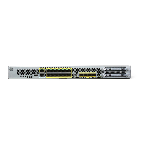
Page 11: Front Panel
Figure 4: Compliance Label on the Chassis Front Panel The following figure shows the front panel of the Firepower 2110 and 2120. See Front Panel LEDs, on page for a description of the LEDs. Cisco Firepower 2100 Series Hardware Installation Guide... - Page 12 The following figure shows the front panel of the Firepower 2130 and 2140. See Front Panel LEDs, on page for a description of the LEDs. Figure 6: Firepower 2130 and 2140 Front Panel Power LED Locator beacon Cisco Firepower 2100 Series Hardware Installation Guide...
- Page 13 • Ethanalyzer packet captures • Tech-support files • Security module log files • Platform bundle image upload using download image usbA: The Type A USB port does not support Cisco Secure Package (CSP) image upload support. Cisco Firepower 2100 Series Hardware Installation Guide...
-
Page 14: Front Panel Leds
LED is blinking so that the system has time to perform a graceful shutdown. • Amber—The system is powering up (before the BIOS boots). This takes one to five seconds at most. • Green—The system is fully powered up. Cisco Firepower 2100 Series Hardware Installation Guide... - Page 15 Immediate attention is required. SSD2 Alert Status Ethernet Link • Off—SSD has normal activity. • Green—The link partner is detected; no activity. • Amber—SSD failure. • Green, flashing—Network activity is detected. Cisco Firepower 2100 Series Hardware Installation Guide...
- Page 16 LED is blinking so that the system has time to perform a graceful shutdown. • Amber—The system is powering up (before the BIOS boots). This takes one to five seconds at most. • Green—The system is fully powered up. Cisco Firepower 2100 Series Hardware Installation Guide...
- Page 17 • Amber—One fan has failed. The system can continue to operate normally, but fan service is required. • Amber, flashing—Two or more fans have failed, or the fan tray has been removed from the system. Immediate attention is required. Cisco Firepower 2100 Series Hardware Installation Guide...
-
Page 18: Rear Panel
Fixed power supply module Fixed fans Two-post grounding lug The two-post grounding lug is Note included in the accessory kit. The following figure shows the rear panel of the Firepower 2130 and 2140. Cisco Firepower 2100 Series Hardware Installation Guide... - Page 19 If you move the power switch to the OFF position before the shutdown command sequence is complete or if you remove the system power cords before the graceful shutdown is complete, disk corruption can occur. Cisco Firepower 2100 Series Hardware Installation Guide...
-
Page 20: Network Modules
FPR2K-NM-8X10G is a single-wide module that supports hot swapping. The eight ports are numbered from top to bottom, left to right. Note Make sure you have the correct firmware package and software version installed to support this network module. Note The FPR2K-NM-8X10G is NEBS-compliant. Cisco Firepower 2100 Series Hardware Installation Guide... -
Page 21: 1-Gb Network Module
FPR2K-NM-8X1G is a single-wide module that supports hot swapping. The eight ports are numbered from top to bottom, left to right. Note Make sure you have the correct firmware package and software version installed to support this network module. Cisco Firepower 2100 Series Hardware Installation Guide... -
Page 22: Hardware Bypass Network Modules
Hardware bypass is supported only on a fixed set of ports. You can pair Port 1 with Port 2, Port 3 with Port 4, but you cannot pair Port 1 with Port 4 for example. Cisco Firepower 2100 Series Hardware Installation Guide... - Page 23 1-Gb Network Module with Hardware Bypass, on page 22 for a description of the 1-G network module. • See Remove and Replace the Network Module, on page 65 for the procedure for removing and replacing single-wide network modules. Cisco Firepower 2100 Series Hardware Installation Guide...
-
Page 24: 1-Gb Sx/10-Gb Sr/10-Gb Lr Network Module With Hardware Bypass
Ethernet X/4 (bottom port) Ethernet X/6 (bottom port) Ports 3 and 4 are paired together to form a Ports 5 and 6 are paired together to form a hardware bypass pair. hardware bypass pair. Cisco Firepower 2100 Series Hardware Installation Guide... - Page 25 IEEE standard. Cable and operating 62.5 160 (FDDI) 13 m distance 62.5 200 (OM1) 16.5 m 33 m 500 (OM2) 41 m 2000 (OM3) 150 m 4700 (OM4) 200 m Cisco Firepower 2100 Series Hardware Installation Guide...
-
Page 26: 1-Gb Network Module With Hardware Bypass
(FPR4K-NM-8X1G-F). Pair ports 1 and 2, 3 and 4, 5 and 6, and 7 and 8 to form hardware bypass paired sets. Note Make sure you have the correct firmware package and software version installed to support this network module. Figure 14: FPR-NM-8X1G-F Cisco Firepower 2100 Series Hardware Installation Guide... -
Page 27: Power Supply Modules
Product ID Numbers, on page 31 for a list of the PIDs associated with the 2100 series power supply modules. Note You cannot mix AC and DC power supply modules in the chassis. Cisco Firepower 2100 Series Hardware Installation Guide... - Page 28 The power supplies can supply up to 350 W power across the input voltage range. The load is shared when both power supply modules are plugged in and running at the same time. Cisco Firepower 2100 Series Hardware Installation Guide...
- Page 29 • Off—Input power not present. • Green, flashing—Input power present, but system is not powered up (power switch is off). • Green—The power supply module is enabled and running. Amber LED (Fail Status) • Off—No fault detected. Cisco Firepower 2100 Series Hardware Installation Guide...
-
Page 30: Fan Modules
SSD in a 2100 series security appliance. Note The 100-GB SSD is restricted to the 2110 and 2120 models. The 200-GB SSD is restricted to the 2130 and 2140 models. Do not mix them. Cisco Firepower 2100 Series Hardware Installation Guide... -
Page 31: Supported Sfp/Sfp+ Transceivers
The SFP/SFP+ transceiver is a bidirectional device with a transmitter and receiver in the same physical package. It is a hot-swappable optical or electrical (copper) interface that plugs into the SFP/SFP+ ports on the fixed ports and the network module ports, and provides Ethernet connectivity. Cisco Firepower 2100 Series Hardware Installation Guide... - Page 32 Caution Although non-Cisco SFPs are allowed, we do not recommend using them because they have not been tested and validated by Cisco. Cisco TAC may refuse support for any interoperability problems that result from using an untested third-party SFP transceiver.
- Page 33 10G-ER-S SFP-10G-ER-S H10GB-CU 1M, 1.5M, 2M, SFP-H10GB-CU1M 2.5M, 3M, 5M SFP-H10GB-CU1-5M SFP-H10GB-CU2M SFP-H10GB-CU2-5 SFP-H10GB-CU3M SFP-H10GB-CU5M H10GB-ACU 7M, 10M SFP-H10GB-ACU7M SFP-H10GB-ACU10M 10G-AOC 1M, 2M, 3M, 5M, SFP-10G-AOC1M 7M, 10M SFP-10G-AOC2M SFP-10G-AOC3M SFP-10G-AOC5M SFP-10G-AOC7M SFP-10G-AOC10M Cisco Firepower 2100 Series Hardware Installation Guide...
-
Page 34: Hardware Specifications
Overview Hardware Specifications Hardware Specifications The following table contains hardware specifications for the Firepower 2100 series security appliance. Specification 2110 2120 2130 2140 Chassis dimensions 1.73 x 16.90 x 19.76 in. (4.4 x 42.9 x 50.2 cm) (H x W x D) Network module 1.2 x 3.7 x 9.6 in. -
Page 35: Product Id Numbers
Product ID Numbers Product ID Numbers The following table lists the PIDs associated with the Firepower 2100 series. All of the PIDs in the table are field-replaceable. See the show inventory and show inventory expand commands in the Cisco FXOS Troubleshooting Guide for the Firepower 2100 Series to display a list of the PIDs for your Firepower 2100. - Page 36 6-port 10-Gb SR hardware bypass network module (spare) FPR4K-NM-8X1G-F 8-port 1-Gb copper hardware bypass network module FPR4K-NM-8X1G-F= 8-port 1-Gb copper hardware bypass network module (spare) FPR2K-NM-BLANK Network module blank slot cover FPR2K-NM-BLANK= Network module blank slot cover (spare) Cisco Firepower 2100 Series Hardware Installation Guide...
-
Page 37: Power Cord Specifications
Only the approved power cords or jumper power cords provided with the security appliance are supported. The following power cords are supported. Figure 17: Argentina CAB-ACR Plug: IRAM 2073 Cord set rating: 10 A, 250 V Connector: IEC 60320/C13 Cisco Firepower 2100 Series Hardware Installation Guide... - Page 38 Figure 19: Brazil CAB-C13-ACB Plug: NBR 14136 Cord set rating: 10 A, 250 V Connector: IEC 60320/C13 Figure 20: China CAB-ACC Plug: GB2099.1-2008/GB1002 Cord set rating: 10 A, 250 V Connector: IEC 60320/C13 Cisco Firepower 2100 Series Hardware Installation Guide...
- Page 39 Figure 22: India PWR-CORD-IND-D Plug: IS 6538-1971 Cord set rating: 10 A, 250 V Connector: IEC 60320/C13 Figure 23: Italy CAB-ACI Plug: CEI 23-16 Cord set rating: 10 A, 250 V Connector: IEC 60320/C13 Cisco Firepower 2100 Series Hardware Installation Guide...
- Page 40 Connector: IEC 60320/C13 Figure 26: Jumper CAB-C13-C14-2M IEC 60320/C14G Cord set rating: 10 A, 250 V Connector: IEC 60320/C13 Figure 27: Korea CAB-AC-C13-KOR Plug: KSC 8305 Cord set rating: 10 A, 250 V Cisco Firepower 2100 Series Hardware Installation Guide...
- Page 41 Figure 29: South Africa CAB-ACSA Plug: SABS 164 Cord set rating: 16 A, 250 V Connector: IEC 60320/C13 Figure 30: Switzerland CAB-ACS Plug: SEV 1011 Cord set rating: 10 A, 250 V Connector: IEC 60320/C13 Cisco Firepower 2100 Series Hardware Installation Guide...
- Page 42 Figure 31: Taiwan CAB-ACTW Plug: CNS10917 Cord set rating: 10 A, 125 V Connector: IEC 60320/C13 Figure 32: United Kingdom CAB-ACU Plug: BS1363A/SS145 Cord set rating: 10 A, 250 V Connector: IEC 60320/C13 Cisco Firepower 2100 Series Hardware Installation Guide...
-
Page 43: Installation Preparation
Use the statement number provided at the end of each warning to locate its translation in the translated safety warnings that accompanied this device. SAVE THESE INSTRUCTIONS Cisco Firepower 2100 Series Hardware Installation Guide... - Page 44 This equipment has been designed for connection to TN and IT power systems. Warning Statement 1017 Restricted Area This unit is intended for installation in restricted access areas. A restricted access area can be accessed by skilled, instructed or qualified personnel. Cisco Firepower 2100 Series Hardware Installation Guide...
- Page 45 Only trained and qualified personnel should be allowed to install, replace, or service this equipment. Warning Statement 1040 Product Disposal Ultimate disposal of this product should be handled according to all national laws and regulations. Cisco Firepower 2100 Series Hardware Installation Guide...
-
Page 46: Safety Recommendations
Then, if an electrical accident occurs, you can act quickly to turn off the power. • Do not work alone if potentially hazardous conditions exist anywhere in your work space. Cisco Firepower 2100 Series Hardware Installation Guide... -
Page 47: Prevent Esd Damage
• Electrical equipment generates heat. Ambient air temperature might not be adequate to cool equipment to acceptable operating temperatures without adequate circulation. Ensure that the room in which you operate your system has adequate air circulation. Cisco Firepower 2100 Series Hardware Installation Guide... -
Page 48: Power Supply Considerations
• Be sure enclosed racks have adequate ventilation. Make sure that the rack is not overly congested as each chassis generates heat. An enclosed rack should have louvered sides and a fan to provide cooling air. Cisco Firepower 2100 Series Hardware Installation Guide... - Page 49 • Baffles can help to isolate exhaust air from intake air, which also helps to draw cooling air through the chassis. The best placement of the baffles depends on the airflow patterns in the rack. Experiment with different arrangements to position the baffles effectively. Cisco Firepower 2100 Series Hardware Installation Guide...
- Page 50 Installation Preparation Rack Configuration Considerations Cisco Firepower 2100 Series Hardware Installation Guide...
-
Page 51: Mount The Chassis
Check for damage and report any discrepancies or damage to your customer service representative. Have the following information ready: • Invoice number of shipper (see the packing slip) • Model and serial number of the damaged unit • Description of damage • Effect of damage on the installation Cisco Firepower 2100 Series Hardware Installation Guide... -
Page 52: Rack-Mount The Chassis Using Brackets
• Two cable management brackets with four 8-32 x 0.375-in. screws (optional) Step 1 Attach a rack-mount bracket to each side of the chassis using the six 8-32 x .375-in. countersink Phillips head screws (three per side). Cisco Firepower 2100 Series Hardware Installation Guide... - Page 53 Rack-mount bracket 8-32 x 0.25-in. countersink Phillip head screws (3 per side) Step 2 (Optional) Attach the cable management bracket to the rack-mount bracket: a) Install the cable management studs into the rack-mount bracket. Cisco Firepower 2100 Series Hardware Installation Guide...
-
Page 54: Rack-Mount The Chassis Using Slide Rails
• When mounting this unit in a partially filled rack, load the rack from the bottom to the top with the heaviest component at the bottom of the rack. • If the rack is provided with stabilizing devices, install the stabilizers before mounting or servicing the unit in the rack. Cisco Firepower 2100 Series Hardware Installation Guide... - Page 55 40°C. This procedure describes how to install the Firepower 2100 series in a rack using slide rails. It applies to all models of the 2100 series. It ships with the Firepower 2130 and 2140 chassis; it is optional for the 2110 and 2120.
- Page 56 8-32 x 0.25-in. countersink Phillips head screws (3 per side) Step 2 (Optional) Attach the cable management bracket to the slide-rail locking bracket: a) Install the cable management studs into the slide-rail locking bracket. Cisco Firepower 2100 Series Hardware Installation Guide...
- Page 57 Figure 37: Install the Screws on the 2110/2120 Chassis and Line up the Inner Rail 8-32-in. screw Inner rail M3x6 mm screw (one per side) Cisco Firepower 2100 Series Hardware Installation Guide...
- Page 58 On the outside of the assembly, push the green arrow button toward the rear to open the securing plate. Figure 39: Front Securing Mechanism Inside the Front End Front mounting pegs Securing plate shown pulled back to open position Works with square slots, 7.1 mm holes, and Note 10-32 threaded holes. Cisco Firepower 2100 Series Hardware Installation Guide...
- Page 59 Slide the release clip toward the rear on both inner rails, and then continue pushing the chassis into the rack until the mounting brackets meet the front of the slide rail. Figure 40: Inner Rail Release Clip Inner rail release clip Inner rail attached to chassis Cisco Firepower 2100 Series Hardware Installation Guide...
-
Page 60: Install The Fips Opacity Shield In A Two-Post Rack
Note Because the FIPS opacity shield covers the serial number on the chassis, the CO should copy the serial number and store it in a secure place. The serial number is needed when you call Cisco TAC. Before you begin You need the following to install the FIPS opacity shield: •... - Page 61 Attach the 7 TELs. See the figure below for the correct placement. Allow the TELs to cure for a minimum of 12 hours. Any deviation in the placement of the TELs means the chassis is not in FIPS mode. Caution Cisco Firepower 2100 Series Hardware Installation Guide...
- Page 62 See the following procedures for how to place the chassis in FIPS mode: • ASA in Platform Mode • ASA in Appliance mode • FTD managed by FMC What to do next See the quick start guide for your operating system for further configuration information. Cisco Firepower 2100 Series Hardware Installation Guide...
-
Page 63: Install The Fips Opacity Shield In A Four-Post Rack
Note Because the FIPS opacity shield covers the serial number on the chassis, the CO should copy the serial number and store it in a secure place. The serial number is needed when you call Cisco TAC. Before you begin You need the following to install the FIPS opacity shield: •... - Page 64 Attach the 7 TELs. See the figure below for the correct placement. Allow the TELs to cure for a minimum of 12 hours. Caution Any deviation in the placement of the TELs means the chassis is not in FIPS mode. Cisco Firepower 2100 Series Hardware Installation Guide...
- Page 65 See the following procedures for how to place the chassis in FIPS mode: • ASA in Platform Mode • ASA in Appliance mode • FTD managed by FMC What to do next See the quick start guide for your operating system for further configuration information. Cisco Firepower 2100 Series Hardware Installation Guide...
-
Page 66: Ground The Chassis
• Two 10-32 x .375-in. screws used to secure the ground lug Step 1 Use a wire-stripping tool to remove approximately 0.75 in. (19 mm) of the covering from the end of the grounding cable. Cisco Firepower 2100 Series Hardware Installation Guide... - Page 67 Make sure that the lug and cable do not interfere with other equipment. Step 7 Prepare the other end of the grounding cable and connect it to an appropriate grounding point in your site to ensure adequate earth ground. Cisco Firepower 2100 Series Hardware Installation Guide...
- Page 68 Mount the Chassis Ground the Chassis What to do next Install the cables according to your default software configuration as described in the quick start guide your version. Cisco Firepower 2100 Series Hardware Installation Guide...
-
Page 69: Maintenance And Upgrade
To remove a network module, loosen the captive screw on the lower left side of the network module and pull out the handle that is connected to the screw. This mechanically ejects the network module from the slot. Cisco Firepower 2100 Series Hardware Installation Guide... -
Page 70: Remove And Replace The Ssd
Remove and Replace the SSD Take note of the following warnings: Warning Statement 1030 Equipment Installation Only trained and qualified personnel should be allowed to install, replace, or service this equipment. Cisco Firepower 2100 Series Hardware Installation Guide... - Page 71 Step 3 To remove the SSD in slot 1, face the front of the chassis, loosen the two captive screws on the SSD, and gently pull it out of the chassis. Cisco Firepower 2100 Series Hardware Installation Guide...
-
Page 72: Remove And Replace The Power Supply Module
When stranded wiring is required, use approved wiring terminations, such as closed-loop or spade-type with upturned lugs. These terminations should be the appropriate size for the wires and should clamp both the insulation and conductor. Cisco Firepower 2100 Series Hardware Installation Guide... - Page 73 Statement 1073 No User-Serviceable Parts No serviceable parts inside. To avoid risk of electric shock, do not open. Power supply modules are hot swappable. You can remove and replace power supply modules while the system is running. Cisco Firepower 2100 Series Hardware Installation Guide...
-
Page 74: Connect The Dc Power Supply Module
Only trained and qualified personnel should be allowed to install, replace, or service this equipment. Warning Statement 1073 No User-Serviceable Parts No serviceable parts inside. To avoid risk of electric shock, do not open. Cisco Firepower 2100 Series Hardware Installation Guide... - Page 75 Connect the DC Power Supply Module For the Cisco 2130 and 2140, the input connector and plug must be UL recognized under UL 486 for field wiring. The connection polarity is from left to right: negative (–), positive (+), and ground.
- Page 76 Do not overtorque the terminal block captive screws. Make sure that the connection is snug, but the wire is not Caution crushed. Verify by tugging lightly on each wire to make sure that they do not move. Cisco Firepower 2100 Series Hardware Installation Guide...
- Page 77 DC power source. In the event of a power source failure, if the second source is still available, it can maintain system operation. Step 9 Verify power supply operation by checking the power supply LED on the front of the chassis. See Front Panel LEDs, on page 10 for the LED values. Cisco Firepower 2100 Series Hardware Installation Guide...
-
Page 78: Secure The Power Cord On The Power Supply Module
Attach the clamp to the power supply module: a) Locate the hexagonal ventilation hole on the power supply module at the center of the plug just below the power connector body (see the following figures). Cisco Firepower 2100 Series Hardware Installation Guide... - Page 79 Adjust the clamp position on the tie wrap so that the clamp is tight against the front of the over mold and the power cord cannot be removed by lightly pulling on it. Cisco Firepower 2100 Series Hardware Installation Guide...
-
Page 80: Remove And Replace The Fan Tray
No serviceable parts inside. To avoid risk of electric shock, do not open. Step 1 Have the fan tray ready for immediate insertion and near the appliance so that you can reinstall the fan tray within 30 seconds. Cisco Firepower 2100 Series Hardware Installation Guide... - Page 81 Step 6 Verify that the fan is operational by checking the fan tray LED. See Front Panel LEDs, on page 10 for a description of the fan LEDs. Cisco Firepower 2100 Series Hardware Installation Guide...
- Page 82 Maintenance and Upgrade Remove and Replace the Fan Tray Cisco Firepower 2100 Series Hardware Installation Guide...
Need help?
Do you have a question about the Firepower 2100 Series and is the answer not in the manual?
Questions and answers