Cisco Firepower 2100 Series Hardware Installation Manual
Hide thumbs
Also See for Firepower 2100 Series:
- Getting started manual (104 pages) ,
- Hardware installation manual (84 pages) ,
- Manual (12 pages)
Table of Contents
Advertisement
Quick Links
Advertisement
Table of Contents

Related Manuals for Cisco Firepower 2100 Series


Summary of Contents for Cisco Firepower 2100 Series
- Page 1 Cisco Firepower 2100 Series Hardware Installation Guide First Published: 2017-05-25 Last Modified: 2022-03-09 Americas Headquarters Cisco Systems, Inc. 170 West Tasman Drive San Jose, CA 95134-1706 http://www.cisco.com Tel: 408 526-4000 800 553-NETS (6387) Fax: 408 527-0883...
- Page 2 Cisco and the Cisco logo are trademarks or registered trademarks of Cisco and/or its affiliates in the U.S. and other countries. To view a list of Cisco trademarks, go to this URL: https://www.cisco.com/c/en/us/about/legal/trademarks.html.
-
Page 3: Table Of Contents
Power Supply Modules Fan Modules SSDs Supported SFP/SFP+ Transceivers Hardware Specifications Product ID Numbers Power Cord Specifications C H A P T E R 2 Installation Preparation General Safety Warnings Network Equipment-Building System (NEBS) Statements Cisco Firepower 2100 Series Hardware Installation Guide... - Page 4 Secure the Power Cord on the Power Supply Module Remove and Replace the Fan Tray Install the FIPS Opacity Shield in a Two-Post Rack Install the FIPS Opacity Shield in a Four-Post Rack Cisco Firepower 2100 Series Hardware Installation Guide...
-
Page 5: Overview
• Power Cord Specifications, on page 37 Features The Cisco Firepower 2100 series security appliance is a standalone modular security services platform. The series includes the Firepower 2110, 2120, 2130, and 2140. See Product ID Numbers, on page 34 for a list of the product IDs (PIDs) associated with the 2100 series. - Page 6 Overview Features Figure 1: Firepower 2110/2120 Figure 2: Firepower 2130/2140 The following table lists the features for the Firepower 2100 series. Table 1: Firepower 2100 Series Features Feature 2110 2120 2130 2140 Security standards • Common Criteria Certification for the Network Device Collaborative Protection certifications Profile, (NDcPPv2.2E), IPS Extended Package (IPSEP v2.11), Firewall...
- Page 7 Four fixed 1-G SFP ports Four fixed 1-G/10-G SFP+ ports pluggable (SFP) ports Pullout asset card Displays serial number Grounding lug On rear panel Locator beacon On front panel Power switch On rear panel Cisco Firepower 2100 Series Hardware Installation Guide...
-
Page 8: Deployment Options
Slot 2 is reserved for the Malware Storage Slot 2 is reserved for the MSP. Pack (MSP). Installed in SSD slot 2 Deployment Options Here are some examples of how you can deploy the Firepower 2100: • As a firewall: Cisco Firepower 2100 Series Hardware Installation Guide... -
Page 9: Package Contents
There are three sets of four screws that you can use to secure the chassis to your rack. Chose the screws that fit your rack. Figure 3: Firepower 2110 and 2120 Package Contents Firepower 2110 or 2120 chassis Console cable RJ-45 to DB-9 (part number 72-3383-01) Cisco Firepower 2100 Series Hardware Installation Guide... - Page 10 See Product ID Numbers, on page 34 for a list of the product IDs (PIDs) associated with the 2130 and 2140 package contents. Cisco Firepower 2100 Series Hardware Installation Guide...
- Page 11 700-106377-01) regulatory and safety guide, and a QR code and URL pointing to the Getting Started Guide. • Four 8-32 x 0.375-inch Phillips screws (part number 48-2696-01) (Optional; in package if ordered) Cisco Firepower 2100 Series Hardware Installation Guide...
-
Page 12: Qr Code Sticker
Figure 6: QR Code Sticker on the Firepower 2100 Front Panel QR code sticker — Serial Number Location The serial number for the Firepower 2100 series chassis is located on the pullout asset card on the front panel. Cisco Firepower 2100 Series Hardware Installation Guide... - Page 13 Serial Number Location Figure 7: Serial Number on the Chassis You can also view additional model information on the compliance label located on the bottom of the chassis. Figure 8: Compliance Label on the Chassis Cisco Firepower 2100 Series Hardware Installation Guide...
-
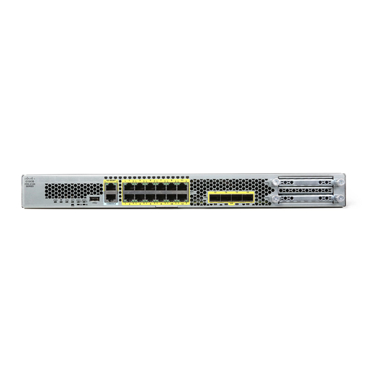
Page 14: Front Panel
Fiber ports 1/13 through 1/16 labeled left to right SSD (slot 2) — The following figure shows the front panel of the Firepower 2130 and 2140. See Front Panel LEDs, on page for a description of the LEDs. Cisco Firepower 2100 Series Hardware Installation Guide... - Page 15 • Hot swapping • USB drive formatted with FAT32 • Boot kickstart image from ROMMON for discovery recovery purposes • Copy files to and from workspace:/ and volatile:/ within local-mgmt. The most relevant files are: Cisco Firepower 2100 Series Hardware Installation Guide...
-
Page 16: Front Panel Leds
• Security module log files • Platform bundle image upload using download image usbA: The Type A USB port does not support Cisco Secure Package (CSP) image upload support. Network Ports The Firepower 2100 chassis has 12 fixed RJ-45 1 G/100 M/10 M) ports. They are numbered from top to bottom, left to right starting with 1 and are named Ethernet 1/1 through Ethernet 1/12. - Page 17 1 flash=10 Mbit, • Blue—Locate is on. 2=100 Mbit, 3=1 Gbit. The Locator LED helps you locate a Note unit that needs physical service attention. This feature is activated in the software. Cisco Firepower 2100 Series Hardware Installation Guide...
- Page 18 • Amber—One fan has failed. The system can continue to operate normally, but fan service is required. • Amber, flashing—Two or more fans have failed, or the fan tray has been removed from the system. Immediate attention is required. Cisco Firepower 2100 Series Hardware Installation Guide...
- Page 19 LED is blinking so that the system has time to perform a graceful shutdown. • Amber—The system is powering up (before the BIOS boots). This takes one to five seconds at most. • Green—The system is fully powered up. Cisco Firepower 2100 Series Hardware Installation Guide...
- Page 20 • Off—The SSD is not present. • Off—The SSD is not present. • Green—The SSD is present; no activity. • Green—The SSD is present; no activity. • Green, flashing—The SSD is active. • Green, flashing—The SSD is active. Cisco Firepower 2100 Series Hardware Installation Guide...
-
Page 21: Rear Panel
• Amber—SSD failure. Rear Panel The following figure shows the rear panel of the Firepower 2110 and 2120. Figure 13: Firepower 2110 and 2120 Rear Panel Power on/off switch Fixed power supply module Cisco Firepower 2100 Series Hardware Installation Guide... - Page 22 Note On the Firepower 2130 and 2140, the OK LEDs on the rear power supplies flash after the switch is turned off; this is expected behavior. Cisco Firepower 2100 Series Hardware Installation Guide...
-
Page 23: Network Modules
The following figure shows the front panel of the 10-Gb network module (FPR2K-NM-8X10G). The FPR2K-NM-8X10G is a single-wide module that supports hot swapping. The eight ports are numbered from top to bottom, left to right. Cisco Firepower 2100 Series Hardware Installation Guide... - Page 24 2100 running ASA with FXOS. See the Cisco Firepower Compatibility Guide and the Cisco ASA Compatibility guide, which provide Cisco software and hardware compatibility, including operating system and hosting environment requirements, for each supported version Note The FPR2K-NM-8X10G is NEBS-compliant.
-
Page 25: 1-Gb Network Module
2100 running ASA with FXOS. See the Cisco Firepower Compatibility Guide and the Cisco ASA Compatibility guide, which provide Cisco software and hardware compatibility, including operating system and hosting environment requirements, for each supported version Note The FPR2K-NM-8X1G is NEBS-compliant. -
Page 26: Hardware Bypass Network Modules
For each network segment you want to monitor inline, connect the cables to pairs of interfaces. • Inline with hardware bypass interfaces—Connection of a hardware bypass paired set. For each network segment that you want to configure inline with fail-open, connect the cables to the paired interface set. Cisco Firepower 2100 Series Hardware Installation Guide... -
Page 27: 1-Gb Sx/10-Gb Sr/10-Gb Lr Network Module With Hardware Bypass
2100 running ASA with FXOS. See the Cisco Firepower Compatibility Guide and the Cisco ASA Compatibility guide, which provide Cisco software and hardware compatibility, including operating system and hosting environment requirements, for each supported version Cisco Firepower 2100 Series Hardware Installation Guide... - Page 28 Table 2: 1-Gb SX Network Module (FPR2K-NM-6X1SX-F) Operating Mode Typical Maximum Insertion loss Normal 0.9 dB 1.4 dB Hardware bypass 1.2 dB 1.7 dB Cisco Firepower 2100 Series Hardware Installation Guide...
- Page 29 41 m 2000 (OM3) 150 m 4700 (OM4) 200 m Table 4: 10-Gb LR Network Module (FPR2K-NM-6X10LR-F) Operating Mode Typical Maximum Insertion loss Normal 1.2 dB 1.6 dB Hardware bypass 1.5 dB 1.9 dB Cisco Firepower 2100 Series Hardware Installation Guide...
-
Page 30: 1-Gb Network Module With Hardware Bypass
Make sure you have the correct firmware package and software version installed to support this network module. See Cisco FXOS Troubleshooting Guide for the Firepower 1000/2100 with Firepower Threat Defense for the procedure to verify your firmware package and software version. See... -
Page 31: Power Supply Modules
You cannot mix AC and DC power supply modules in the chassis. Note After removing power from the chassis by unplugging the power cord, wait at least 10 seconds before turning power back ON. Cisco Firepower 2100 Series Hardware Installation Guide... - Page 32 The power supplies can supply up to 350 W power across the input voltage range. The load is shared when both power supply modules are plugged in and running at the same time. Table 6: DC Power Supply Module Hardware Specifications 2130 2140 Input voltage -48 to -60 V DC Cisco Firepower 2100 Series Hardware Installation Guide...
- Page 33 • Off—Input power not present. • Green, flashing—Input power present, but system is not powered up (power switch is off). • Green—The power supply module is enabled and running. Amber LED (Fail Status) • Off—No fault detected. Cisco Firepower 2100 Series Hardware Installation Guide...
-
Page 34: Fan Modules
SSD in a 2100 series security appliance. Note The 100-GB SSD is restricted to the 2110 and 2120 models. The 200-GB SSD is restricted to the 2130 and 2140 models. Do not mix them. Cisco Firepower 2100 Series Hardware Installation Guide... -
Page 35: Supported Sfp/Sfp+ Transceivers
Take note of the following optical connection warnings: Warning Statement 1051 Laser Radiation Invisible laser radiation may be emitted from disconnected fibers or connectors. Do not stare into beams or view directly with optical instruments. Cisco Firepower 2100 Series Hardware Installation Guide... - Page 36 Caution Although non-Cisco SFPs are allowed, we do not recommend using them because they have not been tested and validated by Cisco. Cisco TAC may refuse support for any interoperability problems that result from using an untested third-party SFP transceiver.
-
Page 37: Hardware Specifications
7M, 10M SFP-10G-AOC2M SFP-10G-AOC3M SFP-10G-AOC5M SFP-10G-AOC7M SFP-10G-AOC10M Hardware Specifications The following table contains hardware specifications for the Firepower 2100 series security appliance. Specification 2110 2120 2130 2140 Chassis dimensions 1.73 x 16.90 x 19.76 inches (4.4 x 42.9 x 50.2 cm) -
Page 38: Product Id Numbers
84.5 (maximum) Product ID Numbers The following table lists the PIDs associated with the Firepower 2100 series. All of the PIDs in the table are field-replaceable. If you need to get a return material authorization (RMA) for any component, see... - Page 39 Cisco Firepower 2110 ASA appliance 1 RU FPR2120-ASA-K9 Cisco Firepower 2120 ASA appliance 1 RU FPR2130-ASA-K9 Cisco Firepower 2130 ASA appliance 1 RU with one network module bay FPR2140-ASA-K9 Cisco Firepower 2140 ASA appliance 1 RU with one network module bay...
- Page 40 Network module blank slot cover FPR2K-NM-BLANK= Network module blank slot cover (spare) FPR2K-CBL-MGMT Cable management brackets FPR2K-CBL-MGMT= Cable management brackets (spare) FPR2K-RM-BRKT= Rack-mount brackets (spare) FPR2K-SLIDE-RAILS Slide rail kit FPR2K-SLIDE-RAILS= Slide rail kit (spare) Cisco Firepower 2100 Series Hardware Installation Guide...
-
Page 41: Power Cord Specifications
Figure 21: Argentina CAB-ACR Plug: IRAM 2073 Cord set rating: 10 A, 250 V Connector: IEC 60320/C13 Figure 22: Australia CAB-ACA Plug: A.S. 3112 Cord set rating: 10 A, 250 V Connector: IEC 60320/C13 Cisco Firepower 2100 Series Hardware Installation Guide... - Page 42 Figure 24: China CAB-ACC Plug: GB2099.1-2008/GB1002 Cord set rating: 10 A, 250 V Connector: IEC 60320/C13 Figure 25: Europe CAB-ACE Plug: CEE 7 VII Cord set rating: 10 A, 250 V Connector: IEC 60320/C13 Cisco Firepower 2100 Series Hardware Installation Guide...
- Page 43 Plug: CEI 23-16 Cord set rating: 10 A, 250 V Connector: IEC 60320/C13 Figure 28: Japan CAB-JPN Plug: JIS C8303 Cord set rating: 12 A, 125 V Connector: IEC 60320/C13 Figure 29: Japan CAB-JPN-3PIN Cisco Firepower 2100 Series Hardware Installation Guide...
- Page 44 Figure 31: Korea CAB-AC-C13-KOR Plug: KSC 8305 Cord set rating: 10 A, 250 V Connector: IEC 60320/C13 Figure 32: North America CAB-AC Plug: NEMA5-15P Cord set rating: 10 A, 125 V Connector: IEC 60320/C13 Cisco Firepower 2100 Series Hardware Installation Guide...
- Page 45 Figure 34: Switzerland CAB-ACS Plug: SEV 1011 Cord set rating: 10 A, 250 V Connector: IEC 60320/C13 Figure 35: Taiwan CAB-ACTW Plug: CNS10917 Cord set rating: 10 A, 125 V Connector: IEC 60320/C13 Cisco Firepower 2100 Series Hardware Installation Guide...
- Page 46 Overview Power Cord Specifications Figure 36: United Kingdom CAB-ACU Plug: BS1363A/SS145 Cord set rating: 10 A, 250 V Connector: IEC 60320/C13 Cisco Firepower 2100 Series Hardware Installation Guide...
-
Page 47: Installation Preparation
Use the statement number provided at the end of each warning statement to locate its translation in the translated safety warnings for this device. SAVE THESE INSTRUCTIONS Cisco Firepower 2100 Series Hardware Installation Guide... - Page 48 (EMI) that might disrupt other equipment, and they direct the flow of cooling air through the chassis. Do not operate the system unless all cards, faceplates, front covers, and rear covers are in place. Cisco Firepower 2100 Series Hardware Installation Guide...
-
Page 49: Network Equipment-Building System (Nebs) Statements
Network Equipment-Building System (NEBS) Statements NEBS describes the environment of a typical United States Regional Bell Operating Company (RBOC) central office. NEBS is the most common set of safety, spatial, and environmental design standards applied to Cisco Firepower 2100 Series Hardware Installation Guide... - Page 50 OSP cabling. The addition of primary protectors is not sufficient protection to connect these interfaces metallically to OSP wiring. This statement applies to the intrabuilding ports listed below: Gigabit Ethernet management port RJ-45 1 G/100 M/10 M auto duplex/auto MDI-X Base-T ports Cisco Firepower 2100 Series Hardware Installation Guide...
-
Page 51: Safety Recommendations
• Wear safety glasses if you are working under any conditions that might be hazardous to your eyes. • Do not perform any action that creates a potential hazard to people or makes the equipment unsafe. Cisco Firepower 2100 Series Hardware Installation Guide... -
Page 52: Maintain Safety With Electricity
If you are currently experiencing shutdowns or unusually high error rates with your existing equipment, these considerations may help you isolate the cause of failures and prevent future problems. Cisco Firepower 2100 Series Hardware Installation Guide... -
Page 53: Site Considerations
• Standard 19-in. (48.3 cm) 4-post EIA rack with mounting rails that conform to English universal hole spacing according to section 1 of ANSI/EIA-310-D-1992. • The rack-mounting posts need to be 2 to 3.5 mm thick to work with the slide rail rack mounting. Cisco Firepower 2100 Series Hardware Installation Guide... - Page 54 • Baffles can help to isolate exhaust air from intake air, which also helps to draw cooling air through the chassis. The best placement of the baffles depends on the airflow patterns in the rack. Experiment with different arrangements to position the baffles effectively. Cisco Firepower 2100 Series Hardware Installation Guide...
-
Page 55: Rack-Mount And Ground The Chassis
Check for damage and report any discrepancies or damage to your customer service representative. Have the following information ready: • Invoice number of shipper (see the packing slip) • Model and serial number of the damaged unit • Description of damage • Effect of damage on the installation Cisco Firepower 2100 Series Hardware Installation Guide... -
Page 56: Rack-Mount The Chassis Using Brackets
• (Optional) Cable management bracket kit (part number 69-100376-01): • Two cable management brackets (part number 700-106377-01) • Four 8-32 x 0.375-inch Phillips screws (part number 48-2696-01) Safety Warnings Take note of the following rack-mount safety warnings: Cisco Firepower 2100 Series Hardware Installation Guide... - Page 57 To reduce the risk of fire or bodily injury, do not operate the unit in an area that exceeds the maximum recommended ambient temperature of 104°F (40°C). Step 1 Attach a rack-mount bracket to each side of the chassis using the six 8-32 x 0.281-inch Phillips screws (three per side). Cisco Firepower 2100 Series Hardware Installation Guide...
- Page 58 Step 2 (Optional) Attach the cable management bracket to the rack-mount bracket: a) Install the cable management screws into the rack-mount bracket. Figure 38: Install the Cable Management Screws into the Rack-Mount Bracket Cisco Firepower 2100 Series Hardware Installation Guide...
-
Page 59: Rack-Mount The Chassis Using Slide Rails
Rack-Mount the Chassis Using Slide Rails This procedure describes how to install the Firepower 2100 series in a rack using slide rails. It applies to all models of the 2100 series. It ships with the Firepower 2130 and 2140 chassis; it is optional for the 2110 and 2120. - Page 60 (Optional) Attach the cable management bracket to the slide-rail locking bracket by installing two 8-32 x 0.375-inch Phillips screws through the inside of the slide-rail locking bracket into the cable management bracket. Repeat for the second cable management bracket. Cisco Firepower 2100 Series Hardware Installation Guide...
- Page 61 Attach the slide-rail locking brackets to each side of the chassis using the six 8-32 x 0.375-inch Phillips screws (three per side). Figure 40: Attach the Slide-Rail Locking Bracket to the Side of the Chassis Chassis Slide-rail locking bracket 8-32 x 0.25-inch Phillips screws (three per side) — Cisco Firepower 2100 Series Hardware Installation Guide...
- Page 62 Using one M3 x 6-mm Phillips screw, secure the inner rail to the side of the chassis to prevent sliding. e) Install the second inner rail to the opposite side of the chassis and secure with the other M3 x 6-mm screw. Cisco Firepower 2100 Series Hardware Installation Guide...
- Page 63 Align the rear of the inner rails that are attached to the chassis sides with the front ends of the empty slide rails on the rack. b) Push the inner rails into the slide rails on the rack until they stop at the internal stops. Cisco Firepower 2100 Series Hardware Installation Guide...
-
Page 64: Ground The Chassis
Recognized Testing Laboratory (NRTL)-listed. In addition, a copper conductor (wires) must be used and the copper conductor must comply with National Electrical Code (NEC) code for ampacity. You need the following items that you provide: Cisco Firepower 2100 Series Hardware Installation Guide... - Page 65 Insert the stripped end of the grounding cable into the open end of the grounding lug. Figure 45: Insert the Cable into the Grounding Lug Step 3 Use the crimping tool to secure the grounding cable in the grounding lug. Cisco Firepower 2100 Series Hardware Installation Guide...
- Page 66 Install the FIPS Opacity Shield in a Four-Post Rack, on page 85 for the procedure. Install the cables according to your default software configuration as described in the Cisco Firepower 2100 Getting Started Guide. Cisco Firepower 2100 Series Hardware Installation Guide...
-
Page 67: Installation, Maintenance, And Upgrade
Take note of the following component replacement safety warnings: Warning Statement 1028 More Than One Power Supply This unit might have more than one power supply connection. To reduce risk of electric shock, remove all connections to de-energize the unit. Cisco Firepower 2100 Series Hardware Installation Guide... - Page 68 To remove a network module, loosen the captive screw on the lower left side of the network module and pull out the handle that is connected to the screw. This mechanically ejects the network module from the slot. Cisco Firepower 2100 Series Hardware Installation Guide...
-
Page 69: Remove And Replace The Ssd
You can install a Malware Storage Pack (MSP) in slot 2. The MSP stores threat detection data for use in future analysis. It supports the Advanced Malware Protection (AMP) software feature. It is used as both storage and as the Malware application repository. RAID is not supported. Cisco Firepower 2100 Series Hardware Installation Guide... - Page 70 Warning Statement 1090 Installation by Skilled Person Only a skilled person should be allowed to install, replace, or service this equipment. See statement 1089 for the definition of a skilled person. Cisco Firepower 2100 Series Hardware Installation Guide...
- Page 71 Do not switch the two SSDs. The MSP must be installed in slot 2. If you remove it and install it in slot 1, all Caution stored file capture data are lost. Step 7 Tighten the captive screws on either side of the SSD. Cisco Firepower 2100 Series Hardware Installation Guide...
-
Page 72: Remove And Replace The Power Supply Module
Warning Statement 1018 Supply Circuit To reduce risk of electric shock and fire, take care when connecting units to the supply circuit so that wiring is not overloaded. Cisco Firepower 2100 Series Hardware Installation Guide... - Page 73 There are no serviceable parts inside. To avoid risk of electric shock, do not open. Warning Statement 1046 Installing or Replacing the Unit To reduce risk of electric shock, when installing or replacing the unit, the ground connection must always be made first and disconnected last. Cisco Firepower 2100 Series Hardware Installation Guide...
- Page 74 Press the latch found on the right of the power supply to disengage the power supply. Step 4 Place your other hand under the power supply module to support it while you slide it out of the chassis. Cisco Firepower 2100 Series Hardware Installation Guide...
-
Page 75: Connect The Dc Power Supply Module
The connection polarity is from left to right: negative (–), positive (+), and ground. Use the handle on the power supply for installation and removal. You must support the module with one hand because of its length. Cisco Firepower 2100 Series Hardware Installation Guide... - Page 76 To reduce the risk of electric shock, secure the modules with the provided screws. Warning Statement 1003 DC Power Disconnection Before performing any of the following procedures, ensure that power is removed from the DC circuit. Cisco Firepower 2100 Series Hardware Installation Guide...
- Page 77 To reduce risk of fire, use copper conductors only. Warning Statement 1028 More Than One Power Supply This unit might have more than one power supply connection. To reduce risk of electric shock, remove all connections to de-energize the unit. Cisco Firepower 2100 Series Hardware Installation Guide...
- Page 78 Statement 1091 Installation by an Instructed Person Only an instructed person or skilled person should be allowed to install, replace, or service this equipment. See statement 1089 for the definition of an instructed or skilled person. Cisco Firepower 2100 Series Hardware Installation Guide...
- Page 79 Do not over torque the terminal block captive screws. Make sure that the connection is snug, but the wire is not crushed. Verify by tugging lightly on each wire to make sure that they do not move. Cisco Firepower 2100 Series Hardware Installation Guide...
-
Page 80: Secure The Power Cord On The Power Supply Module
To secure the power supply module against accidental removal and thus prevent disrupting system performance, use the tie wrap and clamp provided in the accessories kit that ships with your Firepower 2100. Safety Warnings Take note of the following component replacement safety warnings: Cisco Firepower 2100 Series Hardware Installation Guide... - Page 81 Attach the clamp to the tie wrap by holding the clamp with the loop side on the bottom and sliding the tie wrap through the box-shaped channel above the clamp (see the following figure). Cisco Firepower 2100 Series Hardware Installation Guide...
- Page 82 With the clamp side facing up, push the tie wrap in until it is fully engaged. Caution Make sure you have the correct location because you cannot remove the tie wrap from the power supply module once you have installed it without damaging the tie wrap. Cisco Firepower 2100 Series Hardware Installation Guide...
- Page 83 Figure 55: Clamp on Over Mold of Power Cord Power cord Power cord over mold Tie clamp annular teeth Direction to squeeze the clamp tabs Cisco Firepower 2100 Series Hardware Installation Guide...
-
Page 84: Remove And Replace The Fan Tray
Only trained and qualified personnel should be allowed to install, replace, or service this equipment. Warning Statement 1073 No User-Serviceable Parts There are no serviceable parts inside. To avoid risk of electric shock, do not open. Cisco Firepower 2100 Series Hardware Installation Guide... - Page 85 To replace a fan tray, hold the fan tray in front of the fan slot. Step 5 Push the fan tray into the chassis until it is properly seated, and tighten the captive screws. Cisco Firepower 2100 Series Hardware Installation Guide...
-
Page 86: Install The Fips Opacity Shield In A Two-Post Rack
Note Because the FIPS opacity shield covers the serial number on the chassis, the Crypto Officer (CO) should copy the serial number and store it in a secure place. The serial number is needed when you call Cisco TAC. Caution This procedure should be performed only by the CO. - Page 87 Attach the seven TELs. See the figure below for the correct placement. Allow the TELs to cure for a minimum of 12 hours. Caution Any deviation in the placement of the TELs means the chassis is not in FIPS mode. Cisco Firepower 2100 Series Hardware Installation Guide...
- Page 88 Place the chassis in FIPS mode. See the following procedures for how to place the chassis in FIPS mode: • ASA in Platform Mode • ASA in Appliance mode • FTD managed by FMC Cisco Firepower 2100 Series Hardware Installation Guide...
-
Page 89: Install The Fips Opacity Shield In A Four-Post Rack
Because the FIPS opacity shield covers the serial number on the chassis, the CO should copy the serial number and store it in a secure place. The serial number is needed when you call Cisco TAC. You need the following to install the FIPS opacity shield: •... - Page 90 Attach the seven TELs. See the figure below for the correct placement. Allow the TELs to cure for a minimum of 12 hours. Caution Any deviation in the placement of the TELs means the chassis is not in FIPS mode. Cisco Firepower 2100 Series Hardware Installation Guide...
- Page 91 Place the chassis in FIPS mode. See the following procedures for how to place the chassis in FIPS mode: • ASA in Platform Mode • ASA in Appliance mode • FTD managed by FMC Cisco Firepower 2100 Series Hardware Installation Guide...
- Page 92 Installation, Maintenance, and Upgrade Install the FIPS Opacity Shield in a Four-Post Rack What to do next See the Cisco Firepower 2100 Getting Started Guide for your operating system for further configuration information. Cisco Firepower 2100 Series Hardware Installation Guide...
Need help?
Do you have a question about the Firepower 2100 Series and is the answer not in the manual?
Questions and answers