Cisco Firepower 2100 Series Hardware Installation Manual
Hide thumbs
Also See for Firepower 2100 Series:
- Getting started manual (104 pages) ,
- Hardware installation manual (92 pages) ,
- Manual (12 pages)
Table of Contents
Advertisement
Advertisement
Chapters
Table of Contents

Related Manuals for Cisco Firepower 2100 Series


Summary of Contents for Cisco Firepower 2100 Series
- Page 1 Cisco Firepower 2100 Series Hardware Installation Guide First Published: 2017-05-25 Last Modified: 2018-12-07 Americas Headquarters Cisco Systems, Inc. 170 West Tasman Drive San Jose, CA 95134-1706 http://www.cisco.com Tel: 408 526-4000 800 553-NETS (6387) Fax: 408 527-0883...
- Page 2 Cisco has more than 200 offices worldwide. Addresses and phone numbers are listed on the Cisco website at www.cisco.com/go/offices. Cisco and the Cisco logo are trademarks or registered trademarks of Cisco and/or its affiliates in the U.S. and other countries. To view a list of Cisco trademarks, go to this URL: www.cisco.com...
- Page 3 SSDs Supported SFP/SFP+ Transceivers Hardware Specifications Product ID Numbers Power Cord Specifications C H A P T E R 2 Installation Preparation Installation Warnings Safety Recommendations Maintain Safety with Electricity Prevent ESD Damage Cisco Firepower 2100 Series Hardware Installation Guide...
-
Page 4: Table Of Contents
Rack-Mount the Chassis Using Slide Rails Ground the Chassis Connect Cables, Turn on Power, and Verify Connectivity for Cisco Firepower Threat Defense Connect Cables, Turn on Power, and Verify Connectivity Using Cisco Firepower Management Center Connect Cables, Turn on Power, and Verify Connectivity for Cisco ASA... - Page 5 • Power Cord Specifications, on page 32 Features The Cisco Firepower 2100 series security appliance is a standalone modular security services platform. The series includes the Firepower 2110, 2120, 2130, and 2140. See Product ID Numbers, on page 30 for a list of the product IDs (PIDs) associated with the 2100 series.
- Page 6 Figure 1: Firepower 2110/2120 and Firepower 2130/2140 See the Cisco Interactive Library for a video that displays the features and components of the Firepower 2100. The following table lists the features for the Firepower 2100 series. Table 1: Firepower 2100 Series Features Feature 2110...
- Page 7 Ships with one Ships with two 400-W AC power 400-W AC power supply modules supply modules Hot-swappable Hot-swappable DC power supply Yes (optional) Redundant power Four fixed fans One hot-swappable fan tray with four fans Cisco Firepower 2100 Series Hardware Installation Guide...
- Page 8 See Product ID Numbers, on page 30 for a list of the PIDs associated with the 2110 and 2120 package contents. Cisco Firepower 2100 Series Hardware Installation Guide...
- Page 9 See Product ID Numbers, on page 30 for a list of the product IDs (PIDs) associated with the 2130 and 2140 package contents. Cisco Firepower 2100 Series Hardware Installation Guide...
- Page 10 • Start Here document 2 power supply module tie wraps and clamps Serial Number Location The serial number for the Firepower 2100 series chassis is located on the pullout asset card on the front panel. Cisco Firepower 2100 Series Hardware Installation Guide...
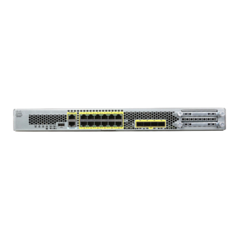
- Page 11 Figure 5: Compliance Label on the Chassis Front Panel The following figure shows the front panel of the Firepower 2110 and 2120. See Front Panel LEDs, on page for a description of the LEDs. Cisco Firepower 2100 Series Hardware Installation Guide...
- Page 12 The following figure shows the front panel of the Firepower 2130 and 2140. See Front Panel LEDs, on page for a description of the LEDs. Figure 7: Firepower 2130 and 2140 Front Panel Power LED Locator beacon Cisco Firepower 2100 Series Hardware Installation Guide...
- Page 13 • Ethanalyzer packet captures • Tech-support files • Security module log files • Platform bundle image upload using download image usbA: The Type A USB port does not support Cisco Secure Package (CSP) image upload support. Cisco Firepower 2100 Series Hardware Installation Guide...
- Page 14 G) ports. They are fiber ports numbered left to right (1/13 through 1/16). Each port has LEDs that represent Link/Activity status. Front Panel LEDs The following figure shows the Firepower 2110 and 2120 front panel LEDs. Figure 8: Firepower 2110 and 2120 Front Panel LEDs Cisco Firepower 2100 Series Hardware Installation Guide...
- Page 15 SSD2 ACT • Off—SSD is not present. • Off—SSD is not present. • Green—SSD is present; no activity. • Green—SSD is present; no activity. • Green, flashing—SSD is active. • Green, flashing—SSD is active. Cisco Firepower 2100 Series Hardware Installation Guide...
- Page 16 Mbit, 2=100 Mbit, 3=1 Gbit. • Amber—Port is enabled, but the link partner is not detected. • Green, flashing—Port is enabled; network activity is detected. The following figure shows the Firepower 2130 and 2140 front panel LEDs. Cisco Firepower 2100 Series Hardware Installation Guide...
- Page 17 LED is blinking so that the system has time to perform a graceful shutdown. • Amber—The system is powering up (before the BIOS boots). This takes one to five seconds at most. • Green—The system is fully powered Cisco Firepower 2100 Series Hardware Installation Guide...
- Page 18 • Amber, flashing—Two or more fans have failed, or the fan tray has been removed from the system. Immediate attention is required. Cisco Firepower 2100 Series Hardware Installation Guide...
- Page 19 Fixed power supply module Fixed fans 2-post grounding lug The 2-post grounding lug is Note included in the accessory kit. The following figure shows the rear panel of the Firepower 2130 and 2140. Cisco Firepower 2100 Series Hardware Installation Guide...
- Page 20 ON. For More Information • See Remove and Replace the Power Supply Module, on page 70 for the procedure for removing and replacing the power supply module in the Firepower 2130 and 2140. Cisco Firepower 2100 Series Hardware Installation Guide...
- Page 21 You can fit four copper SFPs in either the top row of ports or the bottom row of ports. Both rows cannot be populated at the same time, because of the port row spacing. Cisco Firepower 2100 Series Hardware Installation Guide...
- Page 22 You can fit four copper SFPs in either the top row of ports or the bottom row of ports. Both rows cannot be populated at the same time, because of the port row spacing. For a list of copper SFPS, see Supported SFP/SFP+ and QSFP Transceivers. Cisco Firepower 2100 Series Hardware Installation Guide...
- Page 23 Hardware bypass is supported only on a fixed set of ports. You can pair Port 1 with Port 2, Port 3 with Port 4, but you cannot pair Port 1 with Port 4 for example. Cisco Firepower 2100 Series Hardware Installation Guide...
- Page 24 1-G SX/10-G SR/10-G LR Network Module with Hardware Bypass The following figure shows the front panel of the 1-G SX, 10-G SR and 10-G LR fail-to-wire network modules FPRK2-NM-6X1SX-F, FPRK2-NM-6X10SR-F, FPR2K-NM-6X10LR-F). This is a single-wide module that Cisco Firepower 2100 Series Hardware Installation Guide...
- Page 25 Table 2: 1-G SX Network Module (FPR2K-NM-6X1SX-F) Operating Mode Typical Maximum Insertion loss Normal 0.9 dB 1.4 dB Hardware bypass 1.2 dB 1.7 dB Cisco Firepower 2100 Series Hardware Installation Guide...
- Page 26 41 m 2000 (OM3) 150 m 4700 (OM4) 200 m Table 4: 10-G LR Network Module (FPR2K-NM-6X10LR-F) Operating Mode Typical Maximum Insertion loss Normal 1.2 dB 1.6 dB Hardware bypass 1.5 dB 1.9 dB Cisco Firepower 2100 Series Hardware Installation Guide...
- Page 27 The dual power supplies can supply up to 800-W power across the input voltage range. The load is shared when both power supply modules are plugged in and running at the same time. Cisco Firepower 2100 Series Hardware Installation Guide...
- Page 28 6.1 A. See Hardware Specifications, on page 29 for more system specifications. Maximum output power 350 W Redundancy 1+1 redundancy with dual power supply modules Efficiency > 88% at 50% load Cisco Firepower 2100 Series Hardware Installation Guide...
- Page 29 Firepower 2130 and 2140. Fan Modules The Firepower 2110 and 2120 have four fixed fans. If the fans fail, you must send your 2110 or 2120 for RMA. Cisco Firepower 2100 Series Hardware Installation Guide...
- Page 30 SSD LEDs on the front panel. • See Remove and Replace the SSD, on page 68 for the procedure for removing and replacing the SSD. Supported SFP/SFP+ Transceivers Take note of the following warnings: Cisco Firepower 2100 Series Hardware Installation Guide...
- Page 31 It is a hot-swappable optical or electrical (copper) interface that plugs into the SFP/SFP+ ports on the fixed ports and the network module ports, and provides Ethernet connectivity. Figure 16: SFP Dust plug Bail clasp Receive optical bore Transmit optical bore Cisco Firepower 2100 Series Hardware Installation Guide...
- Page 32 Caution Although non-Cisco SFPs are allowed, we do not recommend using them because they have not been tested and validated by Cisco. Cisco TAC may refuse support for any interoperability problems that result from using an untested third-party SFP transceiver.
- Page 33 7M, 10M SFP-10G-AOC2M SFP-10G-AOC3M SFP-10G-AOC5M SFP-10G-AOC7M SFP-10G-AOC10M Hardware Specifications The following table contains hardware specifications for the Firepower 2100 series security appliance. Specification 2110 2120 2130 2140 Chassis dimensions 1.73 x 16.90 x 19.76 in. (4.4 x 42.9 x 50.2 cm)
- Page 34 85.1 (maximum) 84.5 (maximum) Product ID Numbers The following table lists all of the PIDs associated with the Firepower 2100 series. See the show inventory and show inventory expand commands in the Cisco FXOS Troubleshooting Guide for the Firepower 2100 Series to display a list of the PIDs for your Firepower 2100.
- Page 35 Cisco Firepower 2110 ASA appliance 1 RU FPR2120-ASA-K9 Cisco Firepower 2120 ASA appliance 1 RU FPR2130-ASA-K9 Cisco Firepower 2130 ASA appliance 1 RU with one network module bay FPR2140-ASA-K9 Cisco Firepower 2140 ASA appliance 1 RU with one network module bay...
- Page 36 Orders delivered to Argentina, Brazil, and Japan must have the appropriate power cord ordered with the system. Note Only the approved power cords or jumper power cords provided with the security appliance are supported. The following power cords are supported. Cisco Firepower 2100 Series Hardware Installation Guide...
- Page 37 Figure 18: Australia CAB-ACA Plug: A.S. 3112 Cord set rating: 10 A, 250 V Connector: IEC 60320/C13 Figure 19: Brazil CAB-C13-ACB Plug: NBR 14136 Cord set rating: 10 A, 250 V Connector: IEC 60320/C13 Cisco Firepower 2100 Series Hardware Installation Guide...
- Page 38 Figure 21: Europe CAB-ACE Plug: CEE 7 VII Cord set rating: 10 A, 250 V Connector: IEC 60320/C13 Figure 22: India PWR-CORD-IND-D Plug: IS 6538-1971 Cord set rating: 10 A, 250 V Connector: IEC 60320/C13 Cisco Firepower 2100 Series Hardware Installation Guide...
- Page 39 Connector: IEC 60320/C13 Figure 25: Japan CAB-JPN-3PIN Plug: JIS C8303/JIS C8306 Cord set rating: 12 A, 125 V Connector: IEC 60320/C13 Figure 26: Jumper CAB-C13-C14-2M IEC 60320/C14G Cord set rating: 10 A, 250 V Cisco Firepower 2100 Series Hardware Installation Guide...
- Page 40 Figure 28: North America CAB-AC Plug: NEMA5-15P Cord set rating: 10 A, 125 V Connector: IEC 60320/C13 Figure 29: South Africa CAB-ACSA Plug: SABS 164 Cord set rating: 16 A, 250 V Connector: IEC 60320/C13 Cisco Firepower 2100 Series Hardware Installation Guide...
- Page 41 Figure 31: Taiwan CAB-ACTW Plug: CNS10917 Cord set rating: 10 A, 125 V Connector: IEC 60320/C13 Figure 32: United Kingdom CAB-ACU Plug: BS1363A/SS145 Cord set rating: 10 A, 250 V Connector: IEC 60320/C13 Cisco Firepower 2100 Series Hardware Installation Guide...
- Page 42 Overview Power Cord Specifications Cisco Firepower 2100 Series Hardware Installation Guide...
- Page 43 There is the danger of explosion if the battery is replaced incorrectly. Replace the battery only with the same or equivalent type recommended by the manufacturer. Dispose of used batteries according to the manufacturer's instructions. Cisco Firepower 2100 Series Hardware Installation Guide...
- Page 44 To avoid electric shock, do not connect safety extra-low voltage (SELV) circuits to telephone-network voltage (TNV) circuits. LAN ports contain SELV circuits, and WAN ports contain TNV circuits. Some LAN and WAN ports both use RJ-45 connectors. Use caution when connecting cables. Cisco Firepower 2100 Series Hardware Installation Guide...
- Page 45 This product requires short-circuit (overcurrent) protection to be provided as part of the building installation. Install only in accordance with national and local wiring regulations. Warning Statement 1074—Comply with Local and National Electrical Codes Installation of the equipment must comply with local and national electrical codes. Cisco Firepower 2100 Series Hardware Installation Guide...
- Page 46 • Determine whether the person needs rescue breathing or external cardiac compressions; then take appropriate action. • Use the chassis within its marked electrical ratings and product usage instructions. Cisco Firepower 2100 Series Hardware Installation Guide...
-
Page 47: Site Environment
• Check the power at the site before installing the chassis to ensure that it is “clean” (free of spikes and noise). Install a power conditioner, if necessary, to ensure proper voltages and power levels in the appliance input voltage. Cisco Firepower 2100 Series Hardware Installation Guide... -
Page 48: Rack Configuration Considerations
• Baffles can help to isolate exhaust air from intake air, which also helps to draw cooling air through the chassis. The best placement of the baffles depends on the airflow patterns in the rack. Experiment with different arrangements to position the baffles effectively. Cisco Firepower 2100 Series Hardware Installation Guide... -
Page 49: Mount And Connect
• Ground the Chassis, on page 54 • Connect Cables, Turn on Power, and Verify Connectivity for Cisco Firepower Threat Defense, on page • Connect Cables, Turn on Power, and Verify Connectivity Using Cisco Firepower Management Center, on page 60 •... -
Page 50: Rack-Mount The Chassis
• Two cable management brackets with four 8-32 x 0.375-in. screws (optional) Step 1 Attach a rack-mount bracket to each side of the chassis using the six 8-32 x .375-in. countersink Phillips head screws (three per side). Cisco Firepower 2100 Series Hardware Installation Guide... - Page 51 Rack-mount bracket 8-32 x 0.25-in. countersink Phillip head screws (3 per side) Step 2 (Optional) Attach the cable management bracket to the rack-mount bracket: a) Install the cable management studs into the rack-mount bracket. Cisco Firepower 2100 Series Hardware Installation Guide...
-
Page 52: Rack-Mount The Chassis Using Slide Rails
• Ground the Chassis, on page 54 • Connect Cables, Turn on Power, and Verify Connectivity for Cisco Firepower Threat Defense, on page • Connect Cables, Turn on Power, and Verify Connectivity Using Cisco Firepower Management Center, on page 60 •... - Page 53 40°C. This procedure describes how to install the Firepower 2100 series in a rack using slide rails. It applies to all models of the 2100 series. It ships with the Firepower 2130 and 2140 chassis; it is optional for the 2110 and 2120.
-
Page 54: Step 1
Attach the slide-rail locking brackets to each side of the chassis using the six 8-32 x .375-in. countersink Phillips head screws (three per side). Figure 35: Attach the Slide-Rail Locking Bracket to the Side of the Chassis Chassis Slide-rail locking bracket 8-32 x 0.25-in. countersink Phillips head screws (3 per side) Cisco Firepower 2100 Series Hardware Installation Guide... -
Page 55: Step 2
• (2110/2120) Install the three 8-32-in. screws into each side of the chassis, and align the inner rail so that the three slots on the rail line up with the screws on the chassis. Figure 37: Install the Screws on the 2110/2120 Chassis and Line up the Inner Rail 8-32-in. screw Inner rail Cisco Firepower 2100 Series Hardware Installation Guide... - Page 56 On the outside of the assembly, push the green arrow button toward the rear to open the securing plate. Figure 39: Front Securing Mechanism Inside the Front End Cisco Firepower 2100 Series Hardware Installation Guide...
- Page 57 Push the inner rails into the slide rails on the rack until they stop at the internal stops. c) Slide the release clip toward the rear on both inner rails, and then continue pushing the chassis into the rack until the mounting brackets meet the front of the slide rail. Cisco Firepower 2100 Series Hardware Installation Guide...
-
Page 58: Ground The Chassis
• Ground the Chassis, on page 54 • Connect Cables, Turn on Power, and Verify Connectivity for Cisco Firepower Threat Defense, on page • Connect Cables, Turn on Power, and Verify Connectivity Using Cisco Firepower Management Center, on page 60 •... - Page 59 Use a wire-stripping tool to remove approximately 0.75 in. (19 mm) of the covering from the end of the grounding cable. Step 2 Insert the stripped end of the grounding cable into the open end of the grounding lug. Cisco Firepower 2100 Series Hardware Installation Guide...
- Page 60 Prepare the other end of the grounding cable and connect it to an appropriate grounding point in your site to ensure adequate earth ground. What to do next Continue with one of the following: Cisco Firepower 2100 Series Hardware Installation Guide...
-
Page 61: Connect Cables, Turn On Power, And Verify Connectivity For Cisco Firepower Threat Defense
Connect Cables, Turn on Power, and Verify Connectivity for Cisco Firepower Threat Defense • Connect Cables, Turn on Power, and Verify Connectivity for Cisco Firepower Threat Defense, on page • Connect Cables, Turn on Power, and Verify Connectivity Using Cisco Firepower Management Center, on page 60 •... - Page 62 Mount and Connect Connect Cables, Turn on Power, and Verify Connectivity for Cisco Firepower Threat Defense Warning Statement 1025—Use Copper Conductors Only Use copper conductors only. After rack-mounting and grounding the Firepower 2100, follow these steps to connect cables, turn on power, and verify connectivity.
- Page 63 Caution Although non-Cisco SFPs are allowed, we do not recommend using them because they have not been tested and validated by Cisco. Cisco TAC may refuse support for any interoperability problems that result from using an untested third-party SFP transceiver.
- Page 64 Mount and Connect Connect Cables, Turn on Power, and Verify Connectivity Using Cisco Firepower Management Center Connect Cables, Turn on Power, and Verify Connectivity Using Cisco Firepower Management Center Take note of the following warnings: Warning Statement 1005—Circuit Breaker This product relies on the building's installation for short-circuit (overcurrent) protection. Ensure that the...
- Page 65 Mount and Connect Connect Cables, Turn on Power, and Verify Connectivity Using Cisco Firepower Management Center After rack-mounting and grounding the Firepower 2100, follow these steps to connect cables, turn on power, and verify connectivity using the Firepower Management Center (FMC).
-
Page 66: Connect Cables, Turn On Power, And Verify Connectivity For Cisco Asa
Caution Although non-Cisco SFPs are allowed, we do not recommend using them because they have not been tested and validated by Cisco. Cisco TAC may refuse support for any interoperability problems that result from using an untested third-party SFP transceiver. - Page 67 Mount and Connect Connect Cables, Turn on Power, and Verify Connectivity for Cisco ASA Warning Statement 1007—TN and IT Power Systems This equipment has been designed for connection to TN and IT power systems. Warning Statement 1002—DC Power Supply When stranded wiring is required, use approved wiring terminations, such as closed-loop or spade-type with upturned lugs.
- Page 68 Mount and Connect Connect Cables, Turn on Power, and Verify Connectivity for Cisco ASA Figure 45: Connect Cables to Firepower 2100 Interfaces Management 1/1 (management port) WAN modem FXOS: 192.168.45.45 ASA: 192.168.45.1 Internet Ethernet 1/1 (outside, DHCP from modem) Console port (for optional CLI access) Management computer (DHCP) Ethernet 1/2 (inside 192.168.1.1)
- Page 69 Mount and Connect Connect Cables, Turn on Power, and Verify Connectivity for Cisco ASA Although non-Cisco SFPs are allowed, we do not recommend using them because they have not been tested Caution and validated by Cisco. Cisco TAC may refuse support for any interoperability problems that result from using an untested third-party SFP transceiver.
- Page 70 Mount and Connect Connect Cables, Turn on Power, and Verify Connectivity for Cisco ASA Cisco Firepower 2100 Series Hardware Installation Guide...
-
Page 71: Maintenance And Upgrade
To remove a network module, loosen the captive screw on the lower left side of the network module and pull out the handle that is connected to the screw. This mechanically ejects the network module from the slot. Cisco Firepower 2100 Series Hardware Installation Guide... -
Page 72: Remove And Replace The Ssd
Remove and Replace the SSD Take note of the following warnings: Warning Statement 1030—Equipment Installation Only trained and qualified personnel should be allowed to install, replace, or service this equipment. Cisco Firepower 2100 Series Hardware Installation Guide... - Page 73 Step 3 To remove the SSD in slot 1, face the front of the chassis, loosen the two captive screws on the SSD, and gently pull it out of the chassis. Cisco Firepower 2100 Series Hardware Installation Guide...
-
Page 74: Remove And Replace The Power Supply Module
When stranded wiring is required, use approved wiring terminations, such as closed-loop or spade-type with upturned lugs. These terminations should be the appropriate size for the wires and should clamp both the insulation and conductor. Cisco Firepower 2100 Series Hardware Installation Guide... - Page 75 Press the latch found on the middle of the power supply to disengage the power supply. Step 4 Place your other hand under the power supply module to support it while you slide it out of the chassis. Cisco Firepower 2100 Series Hardware Installation Guide...
-
Page 76: Connect The Dc Power Supply Module
No user-serviceable parts inside. Do not open. For the Cisco 2130 and 2140, the input connector and plug must be UL recognized under UL 486 for field wiring. The connection polarity is from left to right: negative (–), positive (+), and ground. - Page 77 0.39 inch (10 mm) + 0.02 inch (0.5 mm). We recommend you use 14 AWG insulated wire. Do not strip more than the recommended length of wire because doing so could leave the wire exposed from Note the terminal block. Cisco Firepower 2100 Series Hardware Installation Guide...
- Page 78 Do not overtorque the terminal block captive screws. Make sure that the connection is snug, but the wire is not Caution crushed. Verify by tugging lightly on each wire to make sure that they do not move. Figure 51: Tighten the Terminal Block Captive Screws Cisco Firepower 2100 Series Hardware Installation Guide...
-
Page 79: Secure The Power Cord On The Power Supply Module
You will hear a click as the tie slides through—it moves in one direction only. To remove the tie wrap from the clamp, push the lever on the closed side of the box-shaped channel and slide out the tie wrap. Cisco Firepower 2100 Series Hardware Installation Guide... - Page 80 With the clamp side facing up, push the tie wrap in until it is fully engaged. Caution Make sure you have the correct location because you cannot remove the tie wrap from the power supply module once you have installed it without damaging the tie wrap. Cisco Firepower 2100 Series Hardware Installation Guide...
- Page 81 Adjust the clamp position on the tie wrap so that the clamp is tight against the front of the over mold and the power cord cannot be removed by lightly pulling on it. Figure 54: Clamp on Over Mold of Power Cord Cisco Firepower 2100 Series Hardware Installation Guide...
-
Page 82: Remove And Replace The Fan Tray
Step 2 To remove a fan tray, face the rear of the chassis, and loosen the two captive screws on the fan tray. Step 3 Pull the fan tray out of the chassis. Cisco Firepower 2100 Series Hardware Installation Guide... - Page 83 Step 6 Verify that the fan is operational by checking the fan tray LED. See Front Panel LEDs, on page 10 for a description of the fan LEDs. Cisco Firepower 2100 Series Hardware Installation Guide...
- Page 84 Maintenance and Upgrade Remove and Replace the Fan Tray Cisco Firepower 2100 Series Hardware Installation Guide...
Need help?
Do you have a question about the Firepower 2100 Series and is the answer not in the manual?
Questions and answers