Cisco Firepower 1100 Series Installation Manual
Hide thumbs
Also See for Firepower 1100 Series:
- Hardware installation manual (30 pages) ,
- Hardware installation manual (42 pages) ,
- Hardware installation manual (42 pages)
Table of Contents
Advertisement
Advertisement
Table of Contents

Related Manuals for Cisco Firepower 1100 Series


Summary of Contents for Cisco Firepower 1100 Series
- Page 1 Cisco Firepower 1100 Series Hardware Installation Guide First Published: 2019-06-13 Last Modified: 2021-03-23 Americas Headquarters Cisco Systems, Inc. 170 West Tasman Drive San Jose, CA 95134-1706 http://www.cisco.com Tel: 408 526-4000 800 553-NETS (6387) Fax: 408 527-0883...
- Page 2 Cisco has more than 200 offices worldwide. Addresses and phone numbers are listed on the Cisco website at www.cisco.com/go/offices. Cisco and the Cisco logo are trademarks or registered trademarks of Cisco and/or its affiliates in the U.S. and other countries. To view a list of Cisco trademarks, go to this URL: https://www.cisco.com/c/en/us/about/legal/trademarks.html.
-
Page 3: Table Of Contents
Maintain Safety with Electricity Prevent ESD Damage Site Environment Site Considerations Power Supply Considerations Rack Configuration Considerations C H A P T E R 3 Mount the Chassis Unpack and Inspect the Chassis Rack-Mount the Chassis Cisco Firepower 1100 Series Hardware Installation Guide... - Page 4 Connect to the Console Port with Mac OS X Connect to the Console Port with Linux C H A P T E R 5 Installation, Maintenance, and Upgrade Replace the SSD Install the FIPS Opacity Shield in a Two-Post Rack Cisco Firepower 1100 Series Hardware Installation Guide...
-
Page 5: Overview
Power Cord Specifications, on page 13 Features The Cisco Firepower 1100 series security appliances are a standalone modular security services platform. They are capable of running multiple security services simultaneously and so are targeted at the data center as a multiservice platform. See... - Page 6 MDI/X-compliant. Port numbering is left to right, top to bottom; ports are named Gigabit Ethernet 1/1 through 1/8. Each port includes a pair of LEDs, one each for connection status and link status. Cisco Firepower 1100 Series Hardware Installation Guide...
- Page 7 AC power supply One fixed AC power supply The power supply is internal; there is no user access. The power supply is not field-replaceable; you must return the chassis to Cisco for power supply replacement. Cisco Firepower 1100 Series Hardware Installation Guide...
- Page 8 Console Ports The Firepower 1100 series has two external console ports, a standard RJ-45 port and a USB Mini B serial port. Only one console port can be active at a time. When a cable is plugged into the USB console port, the RJ-45 port becomes inactive.
-
Page 9: Package Contents
FAT-32 and mount the partition to disk1 again; however, data might be lost. Package Contents The following figure shows the package contents for the Firepower 1100 series. Note that the contents are subject to change, and your exact contents might contain additional or fewer items. Note There are three sets of four screws that you can use to secure the chassis to your rack. -
Page 10: Qr Code Sticker
Firepower 1100 to a network so that the IT department can onboard the device to CDO and configure it remotely. CDO supports Firepower Threat Defense (FTD) version 6.7 and later. The following figure shows the QR code sticker. Cisco Firepower 1100 Series Hardware Installation Guide... - Page 11 QR Code Sticker Figure 3: QR Code Sticker The following figure shows the placement of the QR code sticker on the front panel of the chassis. Figure 4: QR Code on 1100 QR code sticker Cisco Firepower 1100 Series Hardware Installation Guide...
-
Page 12: Serial Number Location
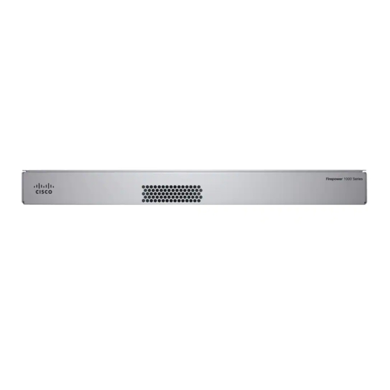
Figure 5: Compliance Label on the Firepower Chassis Front Panel The following figure shows the front panel of the Firepower 1100 series. Note that there are no connectors or LEDs on the front panel. Figure 6: Firepower 1100 Series Front Panel Rear Panel The following figure shows the rear panel of the Firepower 1100 series. -
Page 13: Rear Panel Leds
SSD LED SSD bay Rear Panel LEDs The following figure shows the LEDs on the rear panel of the Firepower 1100 series and describes their states. Figure 8: Firepower 1100 Series Rear Panel LEDs Cisco Firepower 1100 Series Hardware Installation Guide... - Page 14 Status of the SFP transceiver: Power supply status: Link status (L): • Off —Power supply off. • Off—No SFP. • Green—Power supply on. • Amber—SFP present, but no link. • Green, flashing—Link established and transmitting. Cisco Firepower 1100 Series Hardware Installation Guide...
- Page 15 Status of the SSD: • Off— No SSD present or no activity on the SSD. • Green—Activity on the SSD. Note Replace the SSD, on page 35 the procedure for replacing a failed SSD. Cisco Firepower 1100 Series Hardware Installation Guide...
-
Page 16: Hardware Specifications
Product ID Numbers The following table lists the field-replaceable PIDs associated with the Firepower 1100 series. The spare components are ones that you can order and replace yourself. If any internal components fail, you must get a return material authorization (RMA) for the entire chassis. See the Cisco Returns Portal for more information. -
Page 17: Power Cord Specifications
Power Cord Specifications Description FPR1150-NGFW-K9 Cisco Firepower 1150 NGFW appliance FPR1K-RM-SSD200 Cisco Firepower 1100 series 200-GB drive FPR1K-RM-SSD200= Cisco Firepower 1100 series 200-GB drive (spare) FPR1K-CBL-MGMT Cisco Firepower 1100 series cable-management brackets FPR1K-CBL-MGMT= Cisco Firepower 1100 series cable-management brackets (spare) - Page 18 Figure 11: Brazil CAB-C13-ACB 435710 Plug: NBR 14136 Cord set rating: 10 A, 250 V Connector: EL 701B (EN 60320/C13) Figure 12: China CAB-ACC 435702 Plug: V3203C Cord set rating: 10 A, 250 V Connector: V1625 Cisco Firepower 1100 Series Hardware Installation Guide...
- Page 19 Connector: V1625 Figure 14: India CAB-IND-10A 435711 Plug: IA16A3-C Cord set rating: 16 A, 250 V Connector: V1625BS-E Figure 15: Italy CAB-ACI 435705 Plug: IT10S3 Cord set rating: 10 A, 250 V Connector: V1625 Cisco Firepower 1100 Series Hardware Installation Guide...
- Page 20 Figure 17: Korea CAB-AC-C13-KOR 435703 Plug: M2511 Cord set rating: 10 A, 250 V Connector: V1625 Figure 18: North America CAB-AC 435700 Plug: PS204 Cord set rating: 10 A, 250 V Connector: V1625 Cisco Firepower 1100 Series Hardware Installation Guide...
- Page 21 Figure 20: Switzerland CAB-ACS 435707 Plug: SW10ZS3 Cord set rating: 10 A, 250 V Connector: V1625 Figure 21: Taiwan CAB-ACTW 435708 Plug: EL 302 (CNS10917) Cord set rating: 10 A, 125 V Connector: EL 701 (EN 60320/C13) Cisco Firepower 1100 Series Hardware Installation Guide...
- Page 22 Overview Power Cord Specifications Figure 22: United Kingdom CAB-ACU 435709 Plug: 3P BS 1363 Cord set rating: 10 A, 250 V Connector: IEC 60320/C13 Cisco Firepower 1100 Series Hardware Installation Guide...
-
Page 23: Installation Preparation
Use the statement number provided at the end of each warning statement to locate its translation in the translated safety warnings for this device. SAVE THESE INSTRUCTIONS Cisco Firepower 1100 Series Hardware Installation Guide... - Page 24 • Do not use if battery is warped or swollen. • Do not store or use battery in a temperature > 60° C. • Do not store or use battery in low air pressure environment < 69.7 kPa. Cisco Firepower 1100 Series Hardware Installation Guide...
- Page 25 Ultimate disposal of this product should be handled according to all national laws and regulations. Warning Statement 1045 Short-Circuit Protection This product requires short-circuit (overcurrent) protection to be provided as part of the building installation. Install only in accordance with national and local wiring regulations. Cisco Firepower 1100 Series Hardware Installation Guide...
-
Page 26: Safety Recommendations
• Do not perform any action that creates a potential hazard to people or makes the equipment unsafe. • Never attempt to lift an object that is too heavy for one person. Maintain Safety with Electricity Warning Before working on a chassis, be sure the power cord is unplugged. Cisco Firepower 1100 Series Hardware Installation Guide... -
Page 27: Prevent Esd Damage
To avoid equipment failures and reduce the possibility of environmentally caused shutdowns, plan the site layout and equipment locations carefully. If you are currently experiencing shutdowns or unusually high error Cisco Firepower 1100 Series Hardware Installation Guide... -
Page 28: Site Considerations
Consider the following when planning a rack configuration: • If you are mounting a chassis in an open rack, make sure that the rack frame does not block the intake or exhaust ports. Cisco Firepower 1100 Series Hardware Installation Guide... - Page 29 • Baffles can help to isolate exhaust air from intake air, which also helps to draw cooling air through the chassis. The best placement of the baffles depends on the airflow patterns in the rack. Experiment with different arrangements to position the baffles effectively. Cisco Firepower 1100 Series Hardware Installation Guide...
- Page 30 Installation Preparation Rack Configuration Considerations Cisco Firepower 1100 Series Hardware Installation Guide...
-
Page 31: Mount The Chassis
We recommend you install the rack-mount brackets on the rear panel so that the chassis faces the hot aisle. See Package Contents, on page 5 for the rack-mount items in the accessory kit. Cisco Firepower 1100 Series Hardware Installation Guide... - Page 32 We recommend that you install the chassis with the rear panel facing the hot aisle. (See the following illustration for an example of air flow from front panel to back panel.) Figure 23: Install Chassis in Rack Left rack-mount bracket Right rack-mount bracket Hot aisle (chassis rear panel) Cold aisle (chassis front panel) Cisco Firepower 1100 Series Hardware Installation Guide...
- Page 33 Rack-Mount the Chassis Air flow direction, front to back What to do next You can now install the cables and power cord, as described in the Cisco Firepower 1100 Series Getting Started Guide. Cisco Firepower 1100 Series Hardware Installation Guide...
- Page 34 Mount the Chassis Rack-Mount the Chassis Cisco Firepower 1100 Series Hardware Installation Guide...
-
Page 35: Connect To The Console Port
The drivers are OS-specific and not tied to the vendor of the console cable manufacturer. Step 2 Install the driver. Step 3 Connect a 5-pin USB Mini B to the console port as shown in the following figure. Cisco Firepower 1100 Series Hardware Installation Guide... -
Page 36: Connect To The Console Port With Mac Os X
Use the Finder to go to Applications > Utilities > Terminal. Step 2 Connect the OS X USB port to the chassis. Step 3 Enter the following commands to find the OS X USB port number: Cisco Firepower 1100 Series Hardware Installation Guide... -
Page 37: Connect To The Console Port With Linux
Connect to the USB port with the following command followed by the chassis USB port speed Example: root@usb-suse /dev# screen /dev/ttyACM0 9600 Step 5 To disconnect the Linux USB console from the Terminal window, enter Ctrl-a followed by : then quit. Cisco Firepower 1100 Series Hardware Installation Guide... - Page 38 Connect to the Console Port Connect to the Console Port with Linux Cisco Firepower 1100 Series Hardware Installation Guide...
-
Page 39: Installation, Maintenance, And Upgrade
Install the FIPS Opacity Shield in a Two-Post Rack, on page 36 Replace the SSD The Firepower 1100 series ships with an SSD installed. You can replace this SSD should it fail. Before replacing the SSD, you must power off the chassis by pressing the power switch on the rear panel. -
Page 40: Install The Fips Opacity Shield In A Two-Post Rack
Note Because the FIPS opacity shield covers the serial number on the chassis, the CO should copy the serial number and store it in a secure place. The serial number is needed when you call Cisco TAC. Before you begin Caution This procedure should be performed only by the Crypto Officer (CO). - Page 41 Attach 7 of the TELs. See the figure below for the correct placement. Allow the TELs to cure for a minimum of 12 hours. Caution Any deviation in the placement of the TELs means the chassis is not in FIPS mode. Cisco Firepower 1100 Series Hardware Installation Guide...
- Page 42 Step 11 Place the chassis in FIPS mode. See the following procedures for how to place the chassis in FIPS mode: • ASA in Platform Mode • ASA in Appliance mode Cisco Firepower 1100 Series Hardware Installation Guide...
- Page 43 Installation, Maintenance, and Upgrade Install the FIPS Opacity Shield in a Two-Post Rack • FTD managed by FMC What to do next See the Cisco Firepower 1100 Getting Started Guide for further configuration information. Cisco Firepower 1100 Series Hardware Installation Guide...
- Page 44 Installation, Maintenance, and Upgrade Install the FIPS Opacity Shield in a Two-Post Rack Cisco Firepower 1100 Series Hardware Installation Guide...
Need help?
Do you have a question about the Firepower 1100 Series and is the answer not in the manual?
Questions and answers