Advertisement
PowerCage 401 Enclosure • Setup Guide
This setup guide contains installation information about the PowerCage 401 Enclosure using step-by-step instructions. For
complete instructions, see the PowerCage 401 Enclosure User Guide at www.extron.com.
WARNING: Potential risk of severe injury. Installation and service must be performed by authorized personnel only.
AVERTISSEMENT :
par le personnel autorisé uniquement.
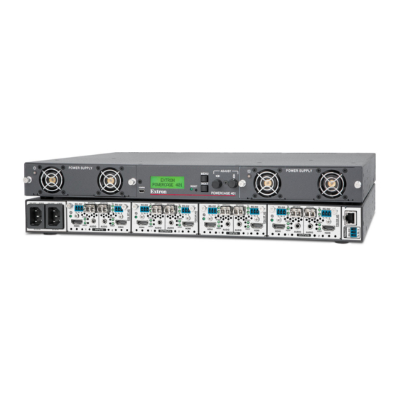
Rear Panel Features
A A A
B B B
100-240V ~ --A MAX
100-240V ~ --A MAX
50-60 Hz
50-60 Hz
Figure 1.
PowerCage 401 Rear Panel
A
Power connector 1 — Connect this port to a 110-240 VAC, 50-60 Hz power source using a standard IEC power cord.
B
Power connector 2 — Connect this port to a 110-240 VAC, 50-60 Hz power source using a standard IEC power cord.
C
Slot 1 — Install a PowerCage 401-compatible board into slot 1.
D
Slot 2 — Install a PowerCage 401-compatible board into slot 2.
E
Slot 3 — Install a PowerCage 401-compatible board into slot 3.
F
Slot 4 — Install a PowerCage 401-compatible board into slot 4.
G
LAN connector — Use an RJ-45 cable to attach this connector to a LAN (Ethernet) for control of the device.
•
Use a straight-through cable for connection to a switch, hub, or router.
•
Use a crossover or a straight-through cable for connection directly to a PC.
H
Remote RS-232 connector — To control the unit, connect an RS-232 device to the 3-pole, 3.5 mm captive screw connector
and configure it as follows: 9600 baud rate, 8 data bits, 1 stop bit, no parity.
Risque potentiel de blessure grave ou de mort. L'installation et l'entretien doivent être effectués
C C C
OPTICAL
OPTICAL
Tx
Tx
Tx
RS-232
RS-232
RS-232
Rx
Rx
Rx
Tx
Rx Tx
Rx
Tx
Tx
Rx G
Tx
Rx G
Tx
Rx G
SIGNAL
SIGNAL
SIGNAL
HDCP
HDCP
HDCP
HDMI
AUDIO
AUDIO
HDMI
HDMI
1
INPUTS
2
1
D D D
E E E
OPTICAL
OPTICAL
OPTICAL
OPTICAL
Tx
Tx
RS-232
RS-232
Rx
Rx
Rx Tx
Rx
Tx
Rx G
Tx
Rx Tx
Tx
Rx G
SIGNAL
SIGNAL
HDCP
HDCP
AUDIO
AUDIO
HDMI
HDMI
AUDIO
AUDIO
INPUTS
2
1
INPUTS
F F F
OPTICAL
OPTICAL
Tx
Tx
Tx
RS-232
RS-232
RS-232
Rx
Rx
Rx
Rx
Tx
Rx Tx
Rx
Tx
Rx G
Tx
Rx G
Tx
Rx G
SIGNAL
SIGNAL
SIGNAL
HDCP
HDCP
HDCP
HDMI
HDMI
AUDIO
AUDIO
HDMI
2
1
INPUTS
2
G G G H H H
1
Advertisement
Table of Contents

Subscribe to Our Youtube Channel
Related Manuals for Extron electronics PowerCage 401


Summary of Contents for Extron electronics PowerCage 401
- Page 1 PowerCage 401 Enclosure • Setup Guide This setup guide contains installation information about the PowerCage 401 Enclosure using step-by-step instructions. For complete instructions, see the PowerCage 401 Enclosure User Guide at www.extron.com. WARNING: Potential risk of severe injury. Installation and service must be performed by authorized personnel only.
- Page 2 Mounting and Cabling Turn off or disconnect all equipment power sources. Mount the PowerCage 401 to a rack using the pre-installed MBD 149 rack ears or use the optional MBU 149 mounting kit for under-desk mounting (see figure 2). P LY...
- Page 3 G G G H H H I I I K K K L L L M M M C C C Figure 4. PowerCage 401 Front Panel Power supply 1 LED Reset button Power supply 1 Menu button Power supply 2...
- Page 4 Fan 4 — For power supply 2 Menus, Configuration, and Adjustments The PowerCage 401 enclosure has a menu system consisting of four main menus that are selected by pressing the front panel Menu button (see figure 4, on page 3) See the figure on previous page. Each main menu consists of submenus that are accessed by pressing the front panel Next button ( ).
Need help?
Do you have a question about the PowerCage 401 and is the answer not in the manual?
Questions and answers