Advertisement
Quick Links
PowerCage 401 Enclosure • Setup Guide
This setup guide contains installation information about the PowerCage 401 Enclosure using step-by-step instructions. For
complete instructions, see the PowerCage 401 Enclosure User Guide at
WARNING:
Potential risk of severe injury. Installation and service must be performed by authorized personnel only.
AVERTISSEMENT :
par le personnel autorisé uniquement.
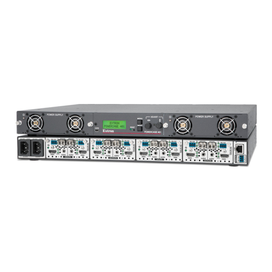
Rear Panel Features
A
B
100-240V ~ --A MAX
100-240V ~ --A MAX
50-60 Hz
50-60 Hz
A
B
C
D
A
B
C
D
E
F
G
H
Mounting and Cabling
1.
2.
Risque potentiel de blessure grave ou de mort. L'installation et l'entretien doivent être effectués
C
D
OPTICAL
OPTICAL
OPTICAL
Tx
Tx
Tx
RS-232
RS-232
RS-232
Rx
Rx
Rx
Tx
Rx G
Tx
Rx Tx
Rx
Tx
Rx G
Tx
Rx G
Tx
Rx Tx
SIGNAL
SIGNAL
SIGNAL
HDCP
HDCP
HDCP
AUDIO
AUDIO
HDMI
AUDIO
HDMI
HDMI
1
INPUTS
2
1
INPUTS
IEC power connector 1
IEC power connector 2
Slot 1
Slot 2
Power connector 1 — Connect this port to a 110-240 VAC, 50-60 Hz power source using a standard
IEC power cord.
Power connector 2 — Connect this port to a 110-240 VAC, 50-60 Hz power source using a standard
IEC power cord.
Slot 1 — Install a PowerCage 401-compatible board into slot 1.
Slot 2 — Install a PowerCage 401-compatible board into slot 2.
Slot 3 — Install a PowerCage 401-compatible board into slot 3.
Slot 4 — Install a PowerCage 401-compatible board into slot 4.
LAN connector — Use an RJ-45 cable to attach this connector to a LAN (Ethernet) for control of the
device.
Use a straight-through cable for connection to a switch, hub, or router.
•
Use a crossover or a straight-through cable for connection directly to a PC.
•
Remote RS-232 connector — To control the unit, connect an RS-232 device to the 3-pole, 3.5 mm
captive screw connector and configure it as follows: 9600 baud rate, 8 data bits, 1 stop bit, no parity.
Turn off or disconnect all equipment power sources.
Mount the PowerCage 401 to a rack using the pre-installed MBD 149 rack ears or use the optional
MBU 149 mounting kit for under-desk mounting. See the illustration on the next page.
www.extron.com
E
OPTICAL
OPTICAL
OPTICAL
Tx
Tx
Tx
RS-232
RS-232
RS-232
Rx
Rx
Rx
Rx
Tx
Rx G
Tx
Rx G
Tx
Rx Tx
Rx
Tx
Rx G
SIGNAL
SIGNAL
SIGNAL
HDCP
HDCP
AUDIO
HDMI
AUDIO
HDCP
HDMI
AUDIO
HDMI
2
1
INPUTS
2
E
Slot 3
F
Slot 4
G
LAN connector
H
RS-232 connector
.
F
G H
OPTICAL
OPTICAL
Tx
Tx
RS-232
RS-232
Rx
Rx
Tx
Rx G
Tx
Rx Tx
Rx
Tx
Rx G
SIGNAL
SIGNAL
HDCP
HDCP
AUDIO
HDMI
AUDIO
HDMI
1
INPUTS
2
1
Advertisement

Related Manuals for Extron electronics PowerCage 401


Summary of Contents for Extron electronics PowerCage 401
- Page 1 Turn off or disconnect all equipment power sources. Mount the PowerCage 401 to a rack using the pre-installed MBD 149 rack ears or use the optional MBU 149 mounting kit for under-desk mounting. See the illustration on the next page.
- Page 2 The guides describe the features of each board and how to set up and cable it. NOTE: The power supplies and boards are hot-swappable; they can be installed or removed without turning off or disconnecting the power to the PowerCage 401 enclosure. CAUTIONS: ATTENTIONS : •...
- Page 3 PowerCage 401 Enclosure • Setup Guide (Continued) -2 3 T IC T IC S IG -2 3 D IO S IG D IO -2 3 T IC T IC S IG -2 3 D IO S IG -2 3 D IO...
- Page 4 — For power supply 2 Menus, Configuration, and Adjustments The PowerCage 401 enclosure has a menu system consisting of four main menus that are selected by pressing the front panel Menu button ( ) See the figure on previous page. Each main menu consists of...
Need help?
Do you have a question about the PowerCage 401 and is the answer not in the manual?
Questions and answers