Racelogic VBOX User Manual
Indoor positioning system vips
Hide thumbs
Also See for VBOX:
- User manual (196 pages) ,
- Quick start manual (15 pages) ,
- User manual (72 pages)
Advertisement
Quick Links
VBOX Indoor Positioning System (VIPS) User Manual
•
01 - VIPS Introduction
•
02 - VIPS Hardware Installation
•
03 - VIPS Rover Connection to VBOX 3i
•
04 - VIPS Site Configuration Software Overview
•
05 - VIPS Using with a VBOX 3i/Standalone
•
06 - VIPS Technical Properties
•
VIPS - PIN OUTS
•
VIPS - Technical Specification
•
How to Update the VIPS Firmware
•
VIPS - Regulatory Information
1
Advertisement

Subscribe to Our Youtube Channel
Related Manuals for Racelogic VBOX


Summary of Contents for Racelogic VBOX
- Page 1 VBOX Indoor Positioning System (VIPS) User Manual • 01 - VIPS Introduction • 02 - VIPS Hardware Installation • 03 - VIPS Rover Connection to VBOX 3i • 04 - VIPS Site Configuration Software Overview • 05 - VIPS Using with a VBOX 3i/Standalone •...
- Page 2 The rover features an integrated VBOX IMU04 (Inertial Measurement Unit) for precise pitch, roll and yaw angular data. It also connects directly to an IMU04 enabled VBOX 3i, enabling additional parameters from the vehicle’s CAN bus to be logged.
-
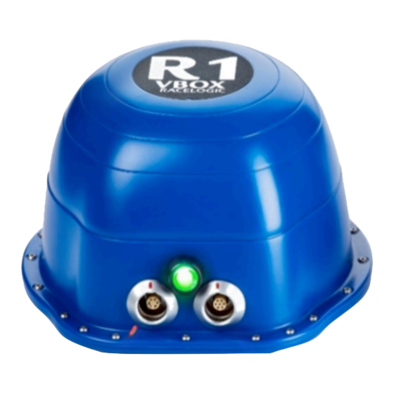
Page 3: Led Behaviour
• The rover automatically connects to the nearest errors in the data. beacons for optimum accuracy. • Connects directly to a VBOX 3i data logger using • Each beacon is numbered for simple installation. only one cable for simple configuration. - Page 4 The unit is set to beacon mode Flashing Green The rover cannot see at least 3 beacons Flashing Orange The unit is syncing the IMU The unit is waiting for VBOX communication (if VB3i Solid Orange connected is selected)
- Page 5 If operating in an outdoor/indoor mode, then the rover will not switch to use the VBOX IPS until 6 beacons are in view. This means that it is only the first 6 beacons that will need to be placed closer together to ensure that 6 beacons are in view before the vehicle enters the test area.
- Page 6 Firmware upgrades and should be covered with the supplied splashproof plug to ensure waterproofness. The VIPS beacons have 4 magnets on the base allowing for easy installation onto any ferrous surface, however Racelogic can supply metallic plates that can attach to a tripod for quick installations. Suitable Beacon Orientations ✔...
- Page 7 Side by side with large height difference ✗ ✗ Tops together ✗ ✗ Tops to base ✗ ✗ Base to base ✗ ✗ Side to base ✗ ✗ Side by side with large height difference, tops away from each other https://racelogic.support/Indoor_Positioning/VBOX_Indoor_Positioning_System_(VIPS)/VIPS_User_Guide/...
- Page 8 The rover should also be mounted in a way such that it has a clear view to the beacons and away from any objects that may block that view (Roof bars, radio antennas etc). https://racelogic.support/Indoor_Positioning/VBOX_Indoor_Positioning_System_(VIPS)/VIPS_User_Guide/...
- Page 9 GNSS time, causing the VIPS system to fail. the VBOX 3i will function the same as when using GNSS in terms of CAN In / Out, data logging (analogue, etc.) and VBOX Test Suite use.
- Page 10 • Insert the 7 way Lemo connector in to the right hand connector on the Rover. • Connect the 25 way connector to the A IN port on the VBOX 3i. • Connect the 5 way Lemo connector to the SER port on the VBOX 3i.
- Page 11 • Insert the 7 way Lemo connector in to the right hand connector on the Rover. • Connect the 25 way connector to the A IN port on the VBOX 3i. • Connect the 5 way Lemo connector to the SER port on the VBOX 3i.
-
Page 12: Getting Started
By selecting New, or a previously saved configuration file, you are then presented with options necessary for correct VIPS operation. The software is navigated by using the menu buttons on the left hand side of the window. Menus include Files, Site, https://racelogic.support/Indoor_Positioning/VBOX_Indoor_Positioning_System_(VIPS)/VIPS_User_Guide/... - Page 13 If you have previously opened a site configuration, pressing Save will overwrite the current file. Alternatively, you can use the dropdown menu to the side of the Save button and select Save as to save the configuration with a different filename. The full VIPS Site Configuration Software User Guide is available here. https://racelogic.support/Indoor_Positioning/VBOX_Indoor_Positioning_System_(VIPS)/VIPS_User_Guide/...
- Page 14 Define the Beacon IDs that will be used as well as the also change the Radio Settings x,y,z distances to the origin Ping Table Upload Upload the site information to the Rover or the Beacons View the expected order the Rover will receive the ‘Ping’ signals from the beacons https://racelogic.support/Indoor_Positioning/VBOX_Indoor_Positioning_System_(VIPS)/VIPS_User_Guide/...
- Page 15 Site Configuration uploaded to the Rover unit, it is now possible to start testing using a VB3i and VIPS. The VBOX 3i will function the same as when using GNSS in terms of CAN In/Out, data logging (analogue, etc.) and VBOX Test Suite use.
- Page 16 VIPS normally outputs locations in degrees latitude and longitude, if however an origin of 0,0 is given, then the conversion to latitude/longitude is skipped and the VIPS rover will output in meters X,Y. When operating with a VB3i, an origin is always needed, when operating in standalone mode, this is optional. https://racelogic.support/Indoor_Positioning/VBOX_Indoor_Positioning_System_(VIPS)/VIPS_User_Guide/...
- Page 17 06 - VIPS Technical Properties VBOX IPS - PIN OUTS VBOX IPS - Technical Connector pin information Specification Beacon/rover specification and size information VBOX IPS - Upgrading Firmware VBOX IPS - Regulatory How to update the VPRS beacon and rover Information Firmware.
- Page 18 VIPS - PIN OUTS Beacon Beacon front view https://racelogic.support/Indoor_Positioning/VBOX_Indoor_Positioning_System_(VIPS)/VIPS_User_Guide/...
- Page 19 Connector 1 - POWER (Lemo 2 PIN) Function +12 V Power Ground Connector 2 (Lemo 7 PIN) Function VIPS Tx VIPS Rx https://racelogic.support/Indoor_Positioning/VBOX_Indoor_Positioning_System_(VIPS)/VIPS_User_Guide/...
- Page 20 Function +12 V Power Ground Chassis Shield Rover Rover front view Connector 1 (Lemo 6 PIN) https://racelogic.support/Indoor_Positioning/VBOX_Indoor_Positioning_System_(VIPS)/VIPS_User_Guide/...
- Page 21 Function Do not use Do not use CAN High CAN Low +12 V Power Chassis Ground Connector 2 (Lemo 7 PIN) Function IMU Rx IMU Tx VIPS Tx VIPS Rx +12 V Power Ground https://racelogic.support/Indoor_Positioning/VBOX_Indoor_Positioning_System_(VIPS)/VIPS_User_Guide/...
- Page 22 Function Chassis Shield https://racelogic.support/Indoor_Positioning/VBOX_Indoor_Positioning_System_(VIPS)/VIPS_User_Guide/...
-
Page 23: Relative Positioning
Maximum velocity 300 km/h Minimum velocity 0.1 km/h Resolution 0.01 km/h Latency 60 ms Relative Positioning Horizontal accuracy <5 cm (95 % CEP*) Update rate 100 Hz Height accuracy 1 m (95% CEP*) Absolute position <10 cm (95% CEP*)^ https://racelogic.support/Indoor_Positioning/VBOX_Indoor_Positioning_System_(VIPS)/VIPS_User_Guide/... - Page 24 0.01 g Update rate 100 Hz Heading Resolution 0.01° Update rate 100 Hz Accuracy (VB3i Kalman Filtered) 0.1° (95% confidence at 60 km/h) Accuracy (Standalone VIPS) 0.4° (95% confidence at 60 km/h) Time Resolution 0.01 s Accuracy 30 ns https://racelogic.support/Indoor_Positioning/VBOX_Indoor_Positioning_System_(VIPS)/VIPS_User_Guide/...
- Page 25 3.64 – 4.38 GHz or 6.16 – 6.69 GHz Transmit power (peak / average) 0 dBm / -41.3 dBm Outputs Rover RS232 Output RS232 Port 1 Position and velocity RS232 Port 2 IMU04 data Output data rate 100 Hz https://racelogic.support/Indoor_Positioning/VBOX_Indoor_Positioning_System_(VIPS)/VIPS_User_Guide/...
- Page 26 Low = 0 V, High = 5 V Output type 1 PPS* Beacon RS232 Output RS232 Port 1 Configuration only Inputs Rover Unit Power Input voltage range 6.5 – 30 V DC Power consumption Digital Input Input Function 1 PPS* https://racelogic.support/Indoor_Positioning/VBOX_Indoor_Positioning_System_(VIPS)/VIPS_User_Guide/...
-
Page 27: Environmental And Physical
0.005 g Environmental and Physical IP rating IP 67 Operating temperature -30°C to +60°C Storage temperature -40°C to +85°C Size (of each beacon/rover) 124 x 124 x 74.5 mm (l x w x h) Weight (of each beacon/rover) 350 g https://racelogic.support/Indoor_Positioning/VBOX_Indoor_Positioning_System_(VIPS)/VIPS_User_Guide/... - Page 28 Beacon/Rover Dimensions Measured in mm. https://racelogic.support/Indoor_Positioning/VBOX_Indoor_Positioning_System_(VIPS)/VIPS_User_Guide/...
- Page 29 VBOX Automotive website. To upgrade the VIPS firmware: 1. Download the Latest VIPS Beacon and VIPS Rover Firmware Files from the VBOX Automotive website and copy these files onto your computer. 2. Download the Racelogic Upgrader Software from the software section of the VBOX Automotive website.
-
Page 30: For Customers In The United States
1. This device may not cause harmful interference, and 2. This device must accept any interference received, Including interference that may cause undesired operation. Changes and Modifications not expressly approved by RACELOGIC can void your authority to operate this equipment under Federal Communications Commissions rules. -
Page 31: Radiation Exposure Statement
RSS-102 pour un environnement non contrôle’. L’antenne(s) utilisée pour ce transmetteur doit etre installé pour fournir une distance de séparation d’au moins 20 cm de toutes les personnes et ne doit pas être co-localisés ou fonctionner en conjunction avec une autre antenne ou transmetteur. https://racelogic.support/Indoor_Positioning/VBOX_Indoor_Positioning_System_(VIPS)/VIPS_User_Guide/...
Need help?
Do you have a question about the VBOX and is the answer not in the manual?
Questions and answers