Racelogic VBOX User Manual
Gps speed sensor
Hide thumbs
Also See for VBOX:
- User manual (196 pages) ,
- Quick start manual (15 pages) ,
- User manual (19 pages)
Table of Contents
Advertisement
Quick Links
Speed Sensor User Manual
•
01 - VBOX Speed Sensor Introduction
•
03 - Installing your VBOX Speed Sensor
•
04 - VBOX Speed Sensor LED Indicators
•
05 - VBOX Speed Sensor Configuration
•
06 - VBOX Speed Sensor Digital Input
•
06 - Speed Sensor Dual Antenna Setup
•
Speed Sensor - Updating the Firmware
•
07 - VBOX Speed Sensor RS232/NMEA Output
•
08 - VBOX Speed Sensor CAN output
•
09 - Speed Sensor PIN OUTS
•
10 - VBOX Speed Sensor Technical Specification
•
11 - VBOX Dual Antenna Speed Sensor Technical Specification
•
11 - VBOX Speed Sensor Inventory
•
12 - VBOX Speed Sensor EC Declaration of Conformity
1
Advertisement
Table of Contents

Related Manuals for Racelogic VBOX


Summary of Contents for Racelogic VBOX
- Page 1 09 - Speed Sensor PIN OUTS • 10 - VBOX Speed Sensor Technical Specification • 11 - VBOX Dual Antenna Speed Sensor Technical Specification • 11 - VBOX Speed Sensor Inventory • 12 - VBOX Speed Sensor EC Declaration of Conformity...
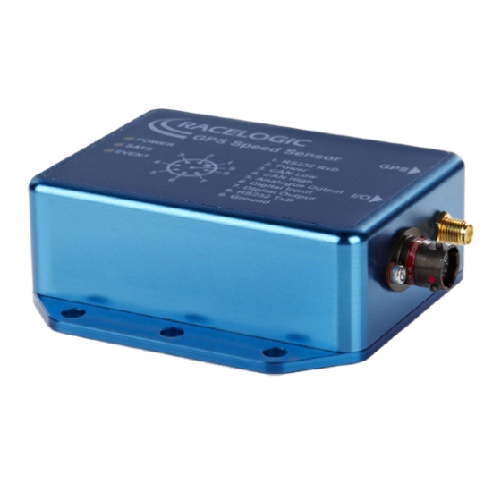
- Page 2 01 - VBOX Speed Sensor Introduction Speed Sensors (VBSS25/VBSS100) The Racelogic Speed Sensors feature versions with 25 Hz and 100 Hz update rates. Based on a range of high-accuracy GNSS engines, you can use the speed sensor to perform non-contact sensing of velocity, providing signal output data on CAN, analogue, digital and serial.
- Page 3 IP66 rated: water and dustproof Wide 7 to 30 V operating range Wide 7 to 30 V operating range Low-current consumption Low-current consumption Online VBOX Test Suite compatibility Online VBOX Test Suite compatibility Compatible with DGPS Basestation CAN stabilisation https://en.racelogic.support//Product_Info/Sensors/Single_and_Dual_Antenna_Speed_Sensors/VBOX_Speed_Sensor_User_Guide/...
- Page 4 01_-_Speed_Sensor_Introduction...
- Page 5 Interfacing with the VBOX Speed Sensor You can use the VBOX Speed Sensor in several different ways, and it is common for the end-user to integrate the speed sensor connector into their own wiring harness. You can purchase a mating connector, Deutsch ASDD606-09PN, from Racelogic for this purpose.
- Page 6 PDF. Power The VBOX Speed Sensor can be powered from a wide range of voltage sources including a Vehicle Cigar adapter, a Racelogic Li-ion battery pack or other sources provided by the user. The maximum operating voltage input must not https://en.racelogic.support//Product_Info/Sensors/Single_and_Dual_Antenna_Speed_Sensors/VBOX_Speed_Sensor_User_Guide/...
- Page 7 30 V DC. Failure to observe this limit could result in damage to the speed sensor. Note: There is no power cable supplied with the VBOX Speed Sensor, but this is available to purchase separately. Note: During extended use, the Speed Sensor's case may become hot. This is normal, however, it is good practice to mount the VBOX Speed Sensor in a position where it has sufficient airflow around the case.
-
Page 8: Gps Coldstart
VBSS100-V4G VBOX Speed Sensor 100 Hz L 127.6 mm* x W 92 mm x H 28.1 mm *Including connectors Outputs There are 4 different types of outputs from the VBOX Speed Sensor: • Analogue • Digital • CAN • RS232... - Page 9 There are two ways to perform a coldstart on the Speed Sensor. • Software 1. Open the VBOX Setup Software. 2. Select the Speed Sensor from the drop-down connection menu and connect to the unit. 3. Press the GPS Coldstart button on the General tab to activate the procedure.
- Page 10 04 - VBOX Speed Sensor LED Indicators There are 3 LED indicators at the top of the VBOX Speed Sensor. These show the status of operation. PWR LED This LED indicates if the VBOX Speed Sensor is powered and working correctly.
-
Page 11: Event Led
1 second when the start line is triggered. The Event LED and Sats LED will both light up in green for 1 second when the finish line is triggered. Note: The ALL the LEDs will be constantly for the duration of a coldstart. https://en.racelogic.support//Product_Info/Sensors/Single_and_Dual_Antenna_Speed_Sensors/VBOX_Speed_Sensor_User_Guide/ 03_-_Speed_Sensor_LED_Indicators... -
Page 12: Software Connection
05 - VBOX Speed Sensor Configuration The VBOX Speed Sensors have default settings applied so that you can use them straight out of the box. You can, however, also configure the settings for your Speed Sensor, by using the VBOX Setup software, which you can download here. -
Page 13: Setup Options
Note: You may see an auto-detect message if the baud rate has been changed from the default value. Select ‘Yes’ to allow the different baud rates to be scanned. Setup options General Tab Menu name/ Description/function button This menu contains the Selected com port drop-down, along with a Connection refresh button and a Disconnect button. https://en.racelogic.support//Product_Info/Sensors/Single_and_Dual_Antenna_Speed_Sensors/VBOX_Speed_Sensor_User_Guide/ 04_-_Speed_Sensor_Configuration... - Page 14 Menu name/ Description/function button This area will provide information about the unit type, software VBOX Information version, serial number and installed firmware version currently being used. Technical information about the GPS Information GPS engine in the connected unit. This feature clears the almanac stored in the GPS engine.
- Page 15 Speed Sensor. When you have completed your setup or you want to cancel your Close setup without writing anything to the unit, click on Close to close the setup window. CAN Tab https://en.racelogic.support//Product_Info/Sensors/Single_and_Dual_Antenna_Speed_Sensors/VBOX_Speed_Sensor_User_Guide/ 04_-_Speed_Sensor_Configuration...
- Page 16 The software has 4 common baud rate values: 1 Mb/s, 500 kb/s, 250 Baud Rate kb/s or 125 kb/s. You can also select a custom baud rate. You can enable or disable the CAN termination internal CAN termination resistance here. https://en.racelogic.support//Product_Info/Sensors/Single_and_Dual_Antenna_Speed_Sensors/VBOX_Speed_Sensor_User_Guide/ 04_-_Speed_Sensor_Configuration...
- Page 17 CAN latency at 15.5 ms. Note: While the unit still transmits all channels, it will stabilise Speed on CAN delay CAN ID 302 when this feature is enabled. You can find more information about the CAN delay function here. Transmitted Identifiers https://en.racelogic.support//Product_Info/Sensors/Single_and_Dual_Antenna_Speed_Sensors/VBOX_Speed_Sensor_User_Guide/ 04_-_Speed_Sensor_Configuration...
- Page 18 These columns allow you to modify the CAN IDs transmitted by the Speed Sensor. Default values are the Racelogic standard ID’s of 0x301, 0x302, 0x307, etc. In Identifier (hex) the Actual column, you can change the ID value, and by ticking the...
- Page 19 You can find more information about the CAN output of the Speed Sensors here. GPS Tab Menu name/ Description/function button This feature gives you the option to DGPS Mode enable differential GPS: None – Differential GPS is off. https://en.racelogic.support//Product_Info/Sensors/Single_and_Dual_Antenna_Speed_Sensors/VBOX_Speed_Sensor_User_Guide/ 04_-_Speed_Sensor_Configuration...
-
Page 20: Serial Tab
GPS engine and set a minimum speed output value if required. GPS Settings The Leap second value was increased to 18 seconds as of December 2016 – you can find more information about this, here. Serial Tab https://en.racelogic.support//Product_Info/Sensors/Single_and_Dual_Antenna_Speed_Sensors/VBOX_Speed_Sensor_User_Guide/ 04_-_Speed_Sensor_Configuration... - Page 21 Menu name Description/function This selects which format the VBOX Speed Sensor will output the Serial data in. NMEA message format is the only user configurable setup. Mode Racelogic: For online connection with VBOX Test Suite. Brake test: For use with Racelogic Brake Test Software.
- Page 22 NMEA Messages by using this drop-down menu. Message Selection: You can select or deselect NMEA messages for transmission by checking and un- checking the boxes next to each message type. Click here for VBOX Speed Sensor Serial Output protocols https://en.racelogic.support//Product_Info/Sensors/Single_and_Dual_Antenna_Speed_Sensors/VBOX_Speed_Sensor_User_Guide/ 04_-_Speed_Sensor_Configuration...
- Page 23 Menu name/ Description/function button Enter the maximum for the speed range you wish to measure. The Speed default speed is set to 400 km/h. The maximum speed at 5 V can be in the range 10 to 1000 km/h. https://en.racelogic.support//Product_Info/Sensors/Single_and_Dual_Antenna_Speed_Sensors/VBOX_Speed_Sensor_User_Guide/ 04_-_Speed_Sensor_Configuration...
- Page 24 Selecting this option outputs a pulse every second, which is synchronised to the GPS clock. GPS Sync Note: This feature is an optional extra which is not available by default. A GPS engine update is required to allow this to work correctly. https://en.racelogic.support//Product_Info/Sensors/Single_and_Dual_Antenna_Speed_Sensors/VBOX_Speed_Sensor_User_Guide/ 04_-_Speed_Sensor_Configuration...
- Page 25 Digital Input You can use the Digital Input and a switch to program the position of virtual lines with the VBOX Speed Sensor. This lets you set Start/Finish lines and Split lines. You can also use the Digital Input and a trigger device to set up a Brake Trigger.
-
Page 26: Tests Tab
Deceleration 10 km/h speed when the trigger is activated. For example, if the trigger speed was 104 km/h then 100 km/h would be the nominated start speed for the corrected brake stop distance. Corrected Distance Start Speed – https://en.racelogic.support//Product_Info/Sensors/Single_and_Dual_Antenna_Speed_Sensors/VBOX_Speed_Sensor_User_Guide/ 04_-_Speed_Sensor_Configuration... - Page 27 Digital or Analogue Lap pulse output duration. If you try to use an invalid setting, Config will not allow it to be written to the unit. Hovering over the Write to unit button will report any invalid settings. https://en.racelogic.support//Product_Info/Sensors/Single_and_Dual_Antenna_Speed_Sensors/VBOX_Speed_Sensor_User_Guide/ 04_-_Speed_Sensor_Configuration...
- Page 28 Splits Files loaded via these buttons will only use the selected information from them –i.e. a file containing a start/finish gate and 6 splits will only load the start/finish gate when loaded via the Start/Finish ‘Load’ button. https://en.racelogic.support//Product_Info/Sensors/Single_and_Dual_Antenna_Speed_Sensors/VBOX_Speed_Sensor_User_Guide/ 04_-_Speed_Sensor_Configuration...
- Page 29 06 - VBOX Speed Sensor Digital Input You can use the Digital Input on the VBOX Speed Sensor to program the position of virtual lines which lets you set Start/ Finish and Split lines. Racelogic can provide different triggers and switches to use with this feature. For more information on available Digital input accessories, click here.
- Page 30 If the software was already connected, you must press ‘Connect’ to refresh the settings. Set a Split line: Press the input switch twice in quick succession when you cross the point you wish the line to be set at. https://en.racelogic.support//Product_Info/Sensors/Single_and_Dual_Antenna_Speed_Sensors/VBOX_Speed_Sensor_User_Guide/ 05_-_Speed_Sensor_Digital_Input...
- Page 31 When the Split line has been marked, the SATS LED will quickly flash green 5 times. In each case, the VBOX Speed Sensor will recognise the lead edge of the first pulse as the activation to set the associated virtual line at the exact point that the user first presses the switch.
- Page 32 06 - Speed Sensor Dual Antenna Setup https://en.racelogic.support//Product_Info/Sensors/Single_and_Dual_Antenna_Speed_Sensors/VBOX_Speed_Sensor_User_Guide/ 06_-_Speed_Sensor_Dual_Antenna_Setup...
- Page 33 Firmware refers to the operating software inside the VBSS Speed Sensor. The firmware is responsible for all of the functions within the VBSS and from time to time, firmware updates will be released by Racelogic to improve or enhance the way that the VBSS works.
- Page 34 07 - VBOX Speed Sensor RS232/NMEA Output The RS232 output is there to provide a connection to a computer so that you can configure the settings of the VBOX Speed Sensor in the VBOX Setup Software. The R232 output can also output NMEA format messages and the Racelogic Braketest format.
- Page 35 0.01° per bit Vertical Velocity 2 (MSB first) 0.01 m/s per bit Lateral Acceleration 2 (MSB first) 0.01 g per bit Longitudinal Acceleration 2 (MSB first) 0.01 g per bit See CRC Calculation 2 (MSB first) example below https://en.racelogic.support//Product_Info/Sensors/Single_and_Dual_Antenna_Speed_Sensors/VBOX_Speed_Sensor_User_Guide/ 07_-_VBOX_Speed_Sensor_RS232%2F%2FNMEA_Output...
- Page 36 CRC:= CRC mod 65536; for i:=7 downto 0 do begin if ( (CRC and 32768)=32768) then begin CRC:= CRC *2 ; CRC:= CRC xor Polynomial; else begin CRC:= CRC *2 ; end; CRC:=CRC mod 65536; end; end; result:=CRC; https://en.racelogic.support//Product_Info/Sensors/Single_and_Dual_Antenna_Speed_Sensors/VBOX_Speed_Sensor_User_Guide/ 07_-_VBOX_Speed_Sensor_RS232%2F%2FNMEA_Output...
- Page 37 UTC, 24 bit unsigned integer Velocity vvvv 4 (MSB first) (m/s), 32 bit IEEE float Heading 2 (MSB first) Heading in degrees (0.01°), 16 bit unsigned integer Event Velocity VVVV 4 (MSB first) Speed at last event (m/s), 32 bit https://en.racelogic.support//Product_Info/Sensors/Single_and_Dual_Antenna_Speed_Sensors/VBOX_Speed_Sensor_User_Guide/ 07_-_VBOX_Speed_Sensor_RS232%2F%2FNMEA_Output...
- Page 38 See CRC Calculation 2 (MSB first) example below Notes: • The 32-bit floats are in Little endian format (low byte first or Intel format) • The Brake distance number is in Big endian format (high byte first or motorola format) https://en.racelogic.support//Product_Info/Sensors/Single_and_Dual_Antenna_Speed_Sensors/VBOX_Speed_Sensor_User_Guide/ 07_-_VBOX_Speed_Sensor_RS232%2F%2FNMEA_Output...
- Page 39 CRC:= CRC mod 65536; for i:=7 downto 0 do begin if ( (CRC and 32768)=32768) then begin CRC:= CRC *2 ; CRC:= CRC xor Polynomial; else begin CRC:= CRC *2 ; end; CRC:=CRC mod 65536; end; end; result:=CRC; https://en.racelogic.support//Product_Info/Sensors/Single_and_Dual_Antenna_Speed_Sensors/VBOX_Speed_Sensor_User_Guide/ 07_-_VBOX_Speed_Sensor_RS232%2F%2FNMEA_Output...
-
Page 40: Nmea Output
NMEA Output IMPORTANT - This is not available on the 5 Hz unit. The VBOX Speed Sensor can output 6 types of NMEA messages, the most commonly used are GPGGA and GPVTG, the contents of which are shown below. $GPGGA,hhmmss.ss,Latitude,N,Longitude,E,FS,NoSV,HDOP,msl,m,Altref,m,DiffAge,DiffStation*cs<C... - Page 41 Course over cogt numeric 77.52 Degrees ground (true) character fixed field True Course over Not output cogm Blank ground (empty) (magnetic) character fixed field Magnetic Speed over numeric 0.004 Knots ground character numeric 0.008 km/h Speed character Kilometers per https://en.racelogic.support//Product_Info/Sensors/Single_and_Dual_Antenna_Speed_Sensors/VBOX_Speed_Sensor_User_Guide/ 07_-_VBOX_Speed_Sensor_RS232%2F%2FNMEA_Output...
- Page 42 ASCII String Name Units Description Format Example hour - fixed field hexadecimal * 0B Checksum <CR> <LF> End of message https://en.racelogic.support//Product_Info/Sensors/Single_and_Dual_Antenna_Speed_Sensors/VBOX_Speed_Sensor_User_Guide/ 07_-_VBOX_Speed_Sensor_RS232%2F%2FNMEA_Output...
- Page 43 08 - VBOX Speed Sensor CAN output The following details the default CAN output from a RLVBSSxx and RLVBSS100SL. This is the Racelogic standard VBOX output, ie. Starting at 0x301 Data format: Motorola Data Bytes Update ID** Rate 0x301 Variable*...
- Page 44 32 bit signed integer, North being positive. 4. Position, Longitude (mmmmm.mmmmm)* 100,000 (11882246 = 0 Degrees, 58.82246 Minutes West). This is a true 32 bit signed integer, West being positive. 5. Velocity, 0.01 knots per bit. 6. Heading, 0.01° per bit. https://en.racelogic.support//Product_Info/Sensors/Single_and_Dual_Antenna_Speed_Sensors/VBOX_Speed_Sensor_User_Guide/ 08_-_VBOX_Speed_Sensor_CAN_output...
- Page 45 36. Longitudinal Velocity, 16-bit signed integer * 100. 37. Centre Of Gravity Slip angle, 16-bit signed integer *100. 38. Front Left, 16-bit signed integer*100. 39. Front Right, 16-bit signed integer*100. 40. Rear Left, 16-bit signed integer*100. 41. Rear Right, 16-bit signed integer*100. https://en.racelogic.support//Product_Info/Sensors/Single_and_Dual_Antenna_Speed_Sensors/VBOX_Speed_Sensor_User_Guide/ 08_-_VBOX_Speed_Sensor_CAN_output...
- Page 46 09 - Speed Sensor PIN OUTS Speed Sensor (RLVBSSxx) Gen1 Gen2 https://en.racelogic.support//Product_Info/Sensors/Single_and_Dual_Antenna_Speed_Sensors/VBOX_Speed_Sensor_User_Guide/ 09_-_Speed_Sensor_PIN_OUTS...
- Page 47 Dual Antenna Speed Sensor https://en.racelogic.support//Product_Info/Sensors/Single_and_Dual_Antenna_Speed_Sensors/VBOX_Speed_Sensor_User_Guide/ 09_-_Speed_Sensor_PIN_OUTS...
- Page 48 Function RS232 Rx +8 V to +30 V Power. Ignition switched feed CAN Low CAN High Analogue Output Lap Marker Input / Brake Trigger Input Speed Pulse / Lap Beacon RS232 Tx Ground https://en.racelogic.support//Product_Info/Sensors/Single_and_Dual_Antenna_Speed_Sensors/VBOX_Speed_Sensor_User_Guide/ 09_-_Speed_Sensor_PIN_OUTS...
-
Page 49: Specifications
10 - VBOX Speed Sensor Technical Specification Specifications VBSS25/VBSS100-V4G Velocity 25 Hz 100 Hz Accuracy 0.1 km/h (averaged over 4 samples) 0.1 km/h (averaged over 4 samples) Units km/h, mph, knots km/h, kph, knots Update rate 25 Hz 100 Hz... -
Page 50: Absolute Positioning
* Specifications will vary depending on the number of satellites used, obstructions, satellite geometry (PDOP), multipath effects, and atmospheric conditions. For maximum system accuracy, always follow best practices for GNSS data collection. Heading 25 Hz 100 Hz Resolution 0.01° 0.01° Accuracy 0.1° 0.1° https://en.racelogic.support//Product_Info/Sensors/Single_and_Dual_Antenna_Speed_Sensors/VBOX_Speed_Sensor_User_Guide/ 10_-_Speed_Sensor_(VBSSxx)_Technical_Specification... - Page 51 -30˚C to +70˚C Storage temp -40°C to +85°C -40°C to +85°C Size 90 mm x 65 mm x 31.85 mm 140 mm x 92 mm x 31.85 mm Connectors Deutsch ASDD Autosport Deutsch ASDD Autosport IP rating IP66 IP66 https://en.racelogic.support//Product_Info/Sensors/Single_and_Dual_Antenna_Speed_Sensors/VBOX_Speed_Sensor_User_Guide/ 10_-_Speed_Sensor_(VBSSxx)_Technical_Specification...
-
Page 52: Can Output
Either Speed, Lateral Acceleration, Longitudinal Data available Acceleration, or Lap Beacon Digital Output data rate Low = 0 V, High = 5 V, Max. frequency 4.4 kHz Data available Speed or Lap Beacon Inputs Input Voltage range 7 – 30 V DC https://en.racelogic.support//Product_Info/Sensors/Single_and_Dual_Antenna_Speed_Sensors/VBOX_Speed_Sensor_User_Guide/ 10_-_Speed_Sensor_(VBSSxx)_Technical_Specification... - Page 53 GPS Antenna 3 V Active Antenna (inc) / 5 V for 100 Hz version Digital Input Set Lap beacon Position / Brake Trigger Event Power, Satellite Count, Event Out Dimensions VBSS25 – 25 Hz 25 Hz Speed Sensor https://en.racelogic.support//Product_Info/Sensors/Single_and_Dual_Antenna_Speed_Sensors/VBOX_Speed_Sensor_User_Guide/ 10_-_Speed_Sensor_(VBSSxx)_Technical_Specification...
- Page 54 VBSS100 – 100 Hz 100 Hz Speed Sensor Discontinued VBOX Speed Sensors VBSS05/VBSS10/VBSS20 Velocity 5 Hz 10 Hz 20 Hz Accuracy 0.1 km/h 0.1 km/h 0.1 km/h Units km/h, mph, kts km/h, mph, kts km/h, mph, kts Update rate 5 Hz...
- Page 55 0.05 % (<50 cm per km) 0.05 % (<50 cm per km) 0.05 % (<50 cm per km) Units m / ft m / ft m / ft Update rate 5 Hz 10 Hz 20 Hz Resolution 1 cm 1 cm 1 cm https://en.racelogic.support//Product_Info/Sensors/Single_and_Dual_Antenna_Speed_Sensors/VBOX_Speed_Sensor_User_Guide/ 10_-_Speed_Sensor_(VBSSxx)_Technical_Specification...
- Page 56 20 cm* 20 cm* GPS upgrade (RLVBUP30) Update rate 5 Hz 10 Hz 20 Hz Resolution 1.8 cm 1.8 cm 1.8 cm Height accuracy 10 m* 6 m* 6 m* Height accuracy 2 m* 2 m* with DGPS https://en.racelogic.support//Product_Info/Sensors/Single_and_Dual_Antenna_Speed_Sensors/VBOX_Speed_Sensor_User_Guide/ 10_-_Speed_Sensor_(VBSSxx)_Technical_Specification...
- Page 57 10 Hz 20 Hz Accuracy 1.00 % 0.50 % 0.50 % Maximum 20 g 20 g Resolution 0.01 g 0.01 g 0.01 g Brake stop Accuracy (Trigger Activated) 5 Hz 10 Hz 20 Hz Accuracy ±20 cm*** ±10 cm*** https://en.racelogic.support//Product_Info/Sensors/Single_and_Dual_Antenna_Speed_Sensors/VBOX_Speed_Sensor_User_Guide/ 10_-_Speed_Sensor_(VBSSxx)_Technical_Specification...
- Page 58 * Circle of Error Probable (CEP): 95 % of the time the position readings will fall within a circle of the stated diameter ** Not using DGPS and crossing the start/finish line at 100 km/h *** Based on <50 m brake stop distance https://en.racelogic.support//Product_Info/Sensors/Single_and_Dual_Antenna_Speed_Sensors/VBOX_Speed_Sensor_User_Guide/ 10_-_Speed_Sensor_(VBSSxx)_Technical_Specification...
- Page 59 0 – 5 V DC Either Speed, Lateral Acceleration, Longitudinal Data available Acceleration, or Lap Beacon Digital Output data rate Low = 0 V, High = 5 V, Max. frequency 4.4 kHz Data available Speed or Lap Beacon https://en.racelogic.support//Product_Info/Sensors/Single_and_Dual_Antenna_Speed_Sensors/VBOX_Speed_Sensor_User_Guide/ 10_-_Speed_Sensor_(VBSSxx)_Technical_Specification...
- Page 60 Digital Input Set Lap beacon Position / Brake Trigger Event Power, Satellite Count, Event Out Dimensions 5 Hz, 10 Hz and 20 Hz 5 Hz, 10 Hz and 20 Hz Speed Sensor VBOX Dual Antenna Speed Sensor – VBSS100SL https://en.racelogic.support//Product_Info/Sensors/Single_and_Dual_Antenna_Speed_Sensors/VBOX_Speed_Sensor_User_Guide/ 10_-_Speed_Sensor_(VBSSxx)_Technical_Specification...
- Page 61 Maximum Velocity 1000 mph Minimum Velocity 0.1 km/h Resolution 0.01 km/h Latency 6.75 ms Distance Accuracy 0.05% (>50 cm per km) Units m / ft Update rate 100 Hz Resolution 1 cm Time Accuracy 0.01 s Resolution 0.01 s https://en.racelogic.support//Product_Info/Sensors/Single_and_Dual_Antenna_Speed_Sensors/VBOX_Speed_Sensor_User_Guide/ 10_-_Speed_Sensor_(VBSSxx)_Technical_Specification...
- Page 62 1.8 mm Update Rate 100 Hz Height Accuracy 6 m (95% CEP*) Height Accuracy with DGPS 2 m (95% CEP*) Acceleration Accuracy 0.5 % Maximum 20 g Resolution 0.01 g Update Rate 100 Hz Heading Accuracy 0.1° Resolution 0.01° https://en.racelogic.support//Product_Info/Sensors/Single_and_Dual_Antenna_Speed_Sensors/VBOX_Speed_Sensor_User_Guide/ 10_-_Speed_Sensor_(VBSSxx)_Technical_Specification...
- Page 63 <0.028° rms at 2.5m antenna separation Definitions * Circle of Error Probable (CEP): 95 % of the time the position readings will fall within a circle of the stated diameter ** Based on <50 m brake stop distance https://en.racelogic.support//Product_Info/Sensors/Single_and_Dual_Antenna_Speed_Sensors/VBOX_Speed_Sensor_User_Guide/ 10_-_Speed_Sensor_(VBSSxx)_Technical_Specification...
- Page 64 0 – 5 V DC Either Speed, Lateral Acceleration, Longitudinal Data available Acceleration, or Lap Beacon Digital Output data rate Low = 0 V, High = 5 V, Max. frequency 4.4 kHz Data available Speed or Lap Beacon https://en.racelogic.support//Product_Info/Sensors/Single_and_Dual_Antenna_Speed_Sensors/VBOX_Speed_Sensor_User_Guide/ 10_-_Speed_Sensor_(VBSSxx)_Technical_Specification...
-
Page 65: Environmental And Physical
Power, Satellite Count, Event Out Environmental and physical Weight Approx 250 g Size 140 mm x 92 mm x 31.85 mm Operating Temperature -30°C to +70°C Storage Temperature -40°C to +85°C Connectors Deutsch ASDD Autosport; Rated IP66 Dimensions https://en.racelogic.support//Product_Info/Sensors/Single_and_Dual_Antenna_Speed_Sensors/VBOX_Speed_Sensor_User_Guide/ 10_-_Speed_Sensor_(VBSSxx)_Technical_Specification... - Page 66 100 Hz Dual Antenna Speed Sensor (V2) https://en.racelogic.support//Product_Info/Sensors/Single_and_Dual_Antenna_Speed_Sensors/VBOX_Speed_Sensor_User_Guide/ 10_-_Speed_Sensor_(VBSSxx)_Technical_Specification...
- Page 67 V3/4 100 Hz Dual Antenna Speed Sensor (V3 and V4) https://en.racelogic.support//Product_Info/Sensors/Single_and_Dual_Antenna_Speed_Sensors/VBOX_Speed_Sensor_User_Guide/ 10_-_Speed_Sensor_(VBSSxx)_Technical_Specification...
- Page 68 11 - VBOX Dual Antenna Speed Sensor Technical Specification https://en.racelogic.support//Product_Info/Sensors/Single_and_Dual_Antenna_Speed_Sensors/VBOX_Speed_Sensor_User_Guide/ 11_-_VBOX_Dual_Antenna_Speed_Sensor_Technical_Specification...
- Page 69 11 - VBOX Speed Sensor Inventory VBOX Speed Sensor 25 Hz Description Quantity Product Code Speed Sensor unit VBSS25 GNSS antenna with SMA RLVBACS018 connector (5 m) 100 Hz Description Speed sensor unit VBSS100-V4G GPS/GLONASS antenna with SMA RLACS156 connector (4 m)
- Page 70 Speed Sensor unit RLVBSSxx GPS Magnetic Antenna RLVBACS018 Dual Antenna Speed Sensor Description Quantity Product Code RLVBSS100 SL Speed Sensor VBSS100 SL GPS/GLONASS Magnetic Antenna RLVBACS156 VBOX Tape Measure RLACS091 VBOX File Manager (Unit Only) VBFMAN Carry Case RLACS106 https://en.racelogic.support//Product_Info/Sensors/Single_and_Dual_Antenna_Speed_Sensors/VBOX_Speed_Sensor_User_Guide/ 11_-_VBOX_Speed_Sensor_Inventory...
- Page 71 Product Code VBSS Interface Cable (Analogue / Digital / CAN / Serial RLCAB093 / Power) VBSS Interface Cable + 5 way Lemo socket for CAN RLCAB093-C Communication VBSS Interface Cable + 5 way Lemo socket for Serial RLCAB093-L Communication https://en.racelogic.support//Product_Info/Sensors/Single_and_Dual_Antenna_Speed_Sensors/VBOX_Speed_Sensor_User_Guide/ 11_-_VBOX_Speed_Sensor_Inventory...
- Page 72 12 - VBOX Speed Sensor EC Declaration of Conformity We declare that this product has been tested to and meet the requirements of: EC Directive 2004/104/EC “Adapting to Technical Progress Council directive 72/245/EEC relating to the radio interference (Electromagnetic Compatibility) of vehicles and amending directive 70/156/EEC on the approximation of the laws of the member states relating to the type-approval of motor vehicles and their trailers.”...
Need help?
Do you have a question about the VBOX and is the answer not in the manual?
Questions and answers