
Related Manuals for powersoft M-Drive


Summary of Contents for powersoft M-Drive
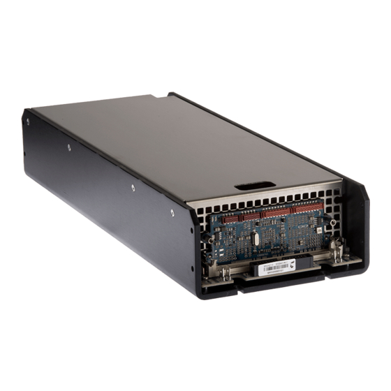
- Page 1 M-Drive Service Manual ©2016 Powersoft Keep this manual powersoft_MDrive_servman_en_v0.6 for future reference...
- Page 2 Intentionally left blank...
- Page 3 At the end of this guide you can find a detailed Switching the Module ON in AC list with the description and the respective Powersoft internal Checking the Rail’s Voltages in AC (With Load) reference code of the spare parts.
-
Page 4: Testing Equipment
M-Drive | SERVICE MANUAL 1. Testing Equipment +18V LM7812 CB000591.R PFC2-PFC4 PSU AUX Voltage Cable CB000684.R DigiMod PFC2-PFC4 MDRIVE PSU AUX Voltage Cable KT000193 IpalMod Interface Board CB000589.R DigiMod Mains DC Cable IpalMod Pressure Sensor Lamp (min.40W/230V, best 60W/230V) NOT INCLUDED... -
Page 5: Mainboard Layout
M-Drive | SERVICE MANUAL 2. Removing the Module’s Cover By means of an M5 Socketed Screwdriver, remove the two metal spacers highlighted on (Fig. 1) and remove the DSP Board by unclipping it from the retaining brackets. (Fig. 1) Using a PH1 Phillips Head Screwdriver, unscrew all 8 screws highlighted on (Fig. -
Page 6: Troubleshooting
M-Drive | SERVICE MANUAL 4. Discharging the Module’s Capacitors Bank: Highlighted on (Fig. 3) are pins 1/2 and 19/20. Connect one end of a 60w Light Bulb as indicated on (Fig. 3) (Fig. 3) 5. Troubleshooting: Ω Checking the Output IGBTs With a Multimeter set to Ohm, check for any short circuit Ω... - Page 7 M-Drive | SERVICE MANUAL Channel 1 Channel 2 5.00 V - 10us 5.00 V - 10us 40Vpp 48KHz 40Vpp 48KHz 5.00 V - 10us 5.00 V - 10us 10Vpp 48KHz 10Vpp 48KHz 5.00 V - 10us 5.00 V - 10us...
- Page 8 M-Drive | SERVICE MANUAL Checking the Power Supply Ω With a Multimeter set to Ohm, check the varistor by probing on the points highlighted on (Fig. 6) There should be no continuity between the two points. ∞Ω (Fig. 6) Ω...
- Page 9 M-Drive | SERVICE MANUAL Checking the PSU Mosfets 18 V 44mA Keep the board alive by supplying 18Vdc through the PL1 connector by means of the PSU AUX Voltage Cable. Using an oscilloscope, check the waveform’s shapes by probing the points indicated...
- Page 10 M-Drive | SERVICE MANUAL 7. Switching the Module On in DC: 30 V 200mA 30 V 200mA DISCONNECT ALL PREVIOUSLY MADE CONNECTIONS Connect the Interface Board and the Pressure Sensor, disconnect the Fans. Portrayed on (Fig. 10) is the connection’s diagram...
- Page 11 M-Drive | SERVICE MANUAL Setup Connect the IpalMod Pressure Sensor to the CN109 connector on the module’s DSP Board. Complete the rest of the connection between the DPC Board the module’s DSP Board. Connect the module to the KT000291 Interface.
- Page 12 M-Drive | SERVICE MANUAL Checking the AUX Tensions With a multimeter set to V, check the tensions on the KT000291 Interface board by probing on the points highlighted on (Fig. 12) +12Vdc: +12Vdc ±10% -12Vdc: -12Vdc ±10% +5Vdc: +5Vdc ±5% (Fig.
- Page 13 M-Drive | SERVICE MANUAL Switching the Module ON in AC Remove al previously made connections. Connect a variac to the PL15 Connector, and slowly increase the voltage to 120 VAC. (Fig. 12) Checking the Rail’s Voltages in AC (With Load)
- Page 14 M-Drive | SERVICE MANUAL Audio Tests Connect a FUnction Generator to input (CN11) By means of the DigiMod Mains DC Cable, connect a Variac to the CN4 Connector and slowly increase the voltage to 120 VAC. Genate a signal @ 0.1 Vrms - 100 Hz Connect an oscilloscope to the CH1 output and confront the resulting wave.
- Page 15 M-Drive | SERVICE MANUAL DPC Board LED Status Charts LED Configuration at Startup Color Label LED Status Green PRESET Green SOLID ON Green READY SOLID ON Yellow TEMP Green ESAVE Green SIGNAL SOLID ON LIMIT SOLID ON PROTECT LED Configuration after 3 seconds...
- Page 16 M-Drive | SERVICE MANUAL 9. Main Board Disassembly: By means of a PH1 Phillips Head screwdriver, screw all 19 screws highlighted in purple. Remove the nut marked orange with a M5 socketed hex screwdriver. Gently lift the board. 10. SilPad Replacement:...
-
Page 17: Known Issues
M-Drive | SERVICE MANUAL 11. Known Issues Excessive Gain on the Output stage Symptom: low input signals yelding to +6dB gain on the output stage. Check R1011, R2011 (marked blue in the picture below), with a multimeter, the resistance should be 100 Ω... -
Page 18: Firmware Update Procedure
Firmware Updater on the Powersoft Website. (RESTRICTED AREA > SERVICE CENTRE AMP MODULES > MDRIVE TOOLS) Contact the Powersoft Service in order to obtain the latest firmware version. Install the RS485 driver. Connect the DPC Interface to the module. - Page 19 M-Drive | SERVICE MANUAL m_drive Select the .bin file (available on the restricted area) Tick the “Use RS485” Box, and select the assigned COM Port Click on the right arrow, the LED on the RS485 should be blinking red. Select the module to be updated.
- Page 20 M-Drive | SERVICE MANUAL 13. Initialization Procedure (restore to Factory Presets) Set up the working area in the same manner described in the FirmWare Update Procedure. The factory preset is available in: restricted area - service amp modules - MDrive tools Switch the MDrive On.
- Page 21 M-Drive | SERVICE MANUAL Verify that the EQ is set to Flat. 14. Repair Kit List: KT000851.R KT000852.R KIT M-DRIVE PSU __FOR REPAIR KIT M-DRIVE AMP 1CH __FOR REPAIR Part Number Description SM010001.R DSP-CTRL BOARD VN000033 FU000026 MAINS FUSE 10A 250 Vdc (5x20 mm)
-
Page 22: Safety Precautions
M-Drive | SERVICE MANUAL IMPORTANT SAFETY ADDENDUM The aim of this addendum is to describe the safety precautions to be undertaken when servicing any Powersoft amplifier/module. WE RECOMMEND THAT ALL SERVICE OPERATIONS ARE CARRIED OUT BY A TRAINED TECHNICIAN IF NOT EXPLICITLY STATED OTHERWISE, DISCONNECT THE AMPLIFIER FROM THE MAINS. - Page 23 Intentionally left blank...
- Page 24 Tel: +39 055 735 0230 Fax: +39 055 735 6235 General inquiries: info@powersoft.it Sales: sales@powersoft.it Application & technical support: support@powersoft.it Service & maintenance: service@powersoft.it powersoft-audio.com Data are subject to change without notice. For latest update please refer to the online version available on www.powersoft-audio.com...
Need help?
Do you have a question about the M-Drive and is the answer not in the manual?
Questions and answers