
Related Manuals for Fronius KD 4000 D-11


Summary of Contents for Fronius KD 4000 D-11
- Page 1 Operating Instructions KD 4000 D-11 Operating Instructions 42,0426,0031,EN 003-10012024...
-
Page 3: Table Of Contents
Contents Safety rules Explanation of safety notices General Proper use Environmental conditions Obligations of the operator Obligations of personnel Mains connection Protecting yourself and others Noise emission values Danger from toxic gases and vapours Danger from flying sparks Risks from mains current and welding current Meandering welding currents EMC Device Classifications EMC measures... - Page 4 Service codes in conjunction with the cold wire feeder and digital gas control option Service codes displayed in conjunction with the cold wire feeder Service codes displayed in conjunction with the digital gas control option Care, maintenance and disposal General remarks Every start-up Every 6 months Disposal Technical data KD 4000 D-11...
-
Page 5: Safety Rules
Safety rules Explanation of DANGER! safety notices Indicates immediate danger. ▶ If not avoided, death or serious injury will result. WARNING! Indicates a potentially hazardous situation. ▶ If not avoided, death or serious injury may result. CAUTION! Indicates a situation where damage or injury could occur. ▶... -
Page 6: Proper Use
Proper use The device is to be used exclusively for its intended purpose. The device is intended solely for the welding processes specified on the rating plate. Any use above and beyond this purpose is deemed improper. The manufacturer shall not be held liable for any damage arising from such usage. Proper use includes: carefully reading and following all the instructions given in the operating in- structions... -
Page 7: Mains Connection
Before leaving the workplace, ensure that people or property cannot come to any harm in your absence. Mains connec- Devices with a higher rating may affect the energy quality of the mains due to tion their current consumption. This may affect a number device types in terms of: Connection restrictions Criteria with regard to the maximum permissible mains impedance Criteria with regard to the minimum short-circuit power requirement... -
Page 8: Noise Emission Values
Noise emission The device generates a maximum sound power level of <80 dB(A) (ref. 1pW) values when idling and in the cooling phase following operation at the maximum per- missible operating point under maximum rated load conditions according to EN 60974-1. -
Page 9: Risks From Mains Current And Welding Current
Never weld close to flammable materials. Flammable materials must be at least 11 metres (36 ft. 1.07 in.) away from the arc, or alternatively covered with an approved cover. A suitable, tested fire extinguisher must be available and ready for use. Sparks and pieces of hot metal may also get into adjacent areas through small gaps or openings. -
Page 10: Meandering Welding Currents
If necessary, provide adequate earthing for the workpiece. Switch off unused devices. Wear a safety harness if working at height. Before working on the device, switch it off and pull out the mains plug. Attach a clearly legible and easy-to-understand warning sign to the device to prevent anyone from plugging the mains plug back in and switching it on again. -
Page 11: Emf Measures
If this is the case, then the operator is obliged to take appropriate action to recti- fy the situation. Check and evaluate the immunity to interference of nearby devices according to national and international regulations. Examples of equipment that may be sus- ceptible to interference from the device include: Safety devices Network, signal and data transfer lines... -
Page 12: Requirement For The Shielding Gas
Never touch the workpiece during or after welding - risk of burns. Slag can jump off cooling workpieces. The specified protective equipment must therefore also be worn when reworking workpieces, and steps must be taken to ensure that other people are also adequately protected. Welding torches and other parts with a high operating temperature must be al- lowed to cool down before handling. -
Page 13: Danger From Escaping Shielding Gas
Protect shielding gas cylinders containing compressed gas from excessive heat, mechanical impact, slag, naked flames, sparks and arcs. Mount the shielding gas cylinders vertically and secure according to instructions to prevent them falling over. Keep the shielding gas cylinders well away from any welding or other electrical circuits. -
Page 14: Safety Measures In Normal Operation
Dies gilt speziell für Richtlinien hinsichtlich Gefährdung bei Transport und Beförderung. Keine aktiven Geräte heben oder transportieren. Geräte vor dem Transport oder dem Heben ausschalten und vom Stromnetz trennen! Vor jedem Transport eines Schweißsystems (z.B. mit Fahrwagen, Kühlgerät, Sch- weißgerät und Drahtvorschub) das Kühlmittel vollständig ablassen, sowie fol- gende Komponenten demontieren: Drahtvorschub Drahtspule... -
Page 15: Commissioning, Maintenance And Repair
(e.g. relevant product standards of the EN 60 974 series). Fronius International GmbH hereby declares that the device is compliant with Directive 2014/53/EU. The full text on the EU Declaration of Conformity can be found at the following address: http://www.fronius.com Devices marked with the CSA test mark satisfy the requirements of the relevant standards for Canada and the USA. -
Page 16: Data Protection
Data protection The user is responsible for the safekeeping of any changes made to the factory settings. The manufacturer accepts no liability for any deleted personal settings. Copyright Copyright of these operating instructions remains with the manufacturer. The text and illustrations are all technically correct at the time of printing. We reserve the right to make changes. -
Page 17: General
TransTig 4000 / 5000 Job MagicWave 2200 / 2500 / 3000 MagicWave 4000 / 5000 Job Cold wire feeder KD 4000 D-11 Application area The KD 4000 D can be used for all types of TIG welding and is especially suited to robot applications and automated tasks. -
Page 18: Control Elements And Connections
Control elements and connections General Owing to software updates, you may find that your machine has certain functions that are not described in these Operating Instructions, or vice-versa. Certain il- lustrations may also differ slightly from the actual controls on your device, but these controls function in exactly the same way. -
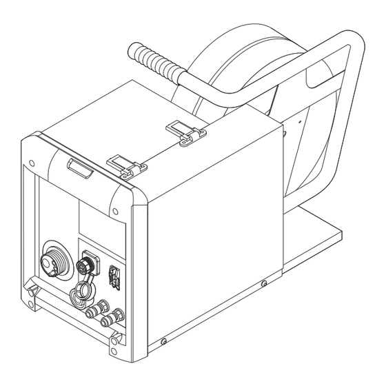
Page 19: Cold Wire Feeder Rear
Cold wire feeder Bushing for control socket rear for connecting a welding torch with a conventional control plug (+) socket with bayonet latch LocalNet connection Interconnecting hosepack Coolant return-flow connec- tion socket (red) Interconnecting hosepack Water flow connection (blue) Interconnecting hosepack Rear Cold wire feeder right side... -
Page 20: Cold Wire Feeder Underside
Hold the button for up to one second Irrespective of what value has been set, the wire speed remains at 1 m/min or 39.37 ipm for the first second. Hold the button for up to 2.5 seconds After one second has elapsed, the wire speed increases at a uniform rate over the next 1.5 seconds. -
Page 21: Placing The Cold Wire Feeder On The Power Source
Placing the cold wire feeder on the power source General If the TransTig 4000/5000 and MagicWave 4000/5000 power sources have been fixed onto a trolley with cooling unit, the cold wire feeder can be placed on the optional wirefeeder holder on the trolley. Placing the cold CAUTION! wire feeder on... -
Page 22: Connect The Cold Wire Feeder To The Power Source
Connect the cold wire feeder to the power source General The cold wire feeder is connected to the power source using the interconnecting hosepack. Connect the cold WARNING! wire feeder to the power source Danger from incorrect installation This can result in serious injury and damage to property. ▶... -
Page 23: Fitting The Welding Torch
Fitting the welding torch Fit the welding Switch the power source mains torch switch to the "Off" position Connect welding torch control plug to the LocalNet port (3) or torch control connection (4) and fasten If present: connect colour-coded external water connections for wa- ter flow (5) and return (6) Plug welding potential bayonet plug into current socket (1) and... -
Page 24: Inserting The Wirespool
Inserting the wirespool Safety CAUTION! Risk of injury from springiness of spooled welding wire. This can result in serious injury and damage to property. ▶ When threading in the welding wire, hold the end of it firmly, to prevent any injuries that might be caused by the wire flicking back. - Page 25 Close left side panel of the cold wire feeder again Always adjust the brake so that the wirespool does not continue unreeling after the end of welding - but without overtightening the clamping screw, as this might cause motor overload. WARNING! Danger from incorrect installation This can result in serious injury and damage to property.
-
Page 26: Inserting/Replacing Feed Rollers
Inserting/replacing feed rollers General remarks In order to achieve optimum wire electrode feed, the feed rollers must be suit- able for the diameter and alloy of the wire being welded. IMPORTANT! Only use feed rollers that match the wire electrode. An overview of the feed rollers available and their possible areas of use can be found in the spare parts lists. -
Page 27: Inserting The Wirespool, Inserting The Basket-Type Spool
Inserting the wirespool, inserting the basket-type spool Safety CAUTION! Danger from springiness of spooled wire electrode. This can result in severe injuries. ▶ When inserting the wirespool/basket-type spool, hold the end of the wire electrode firmly to avoid injuries caused by the wire electrode springing back. CAUTION! Danger from falling wirespool/basket-type spool. - Page 28 WARNING! Danger from falling wirespool/basket-type spool. This can result in serious personal injury and damage to property. ▶ Ensure that the wirespool/basket-type spool including basket-type spool ad- apter is always firmly seated on the wirespool holder.
-
Page 29: Inserting The Basket-Type Spool
Inserting the NOTE! basket-type spool When working with basket-type spools, use only the basket-type spool adapter supplied with the wire-feed unit! USA wire-feed units are supplied without bas- ket-type spool adapters. CAUTION! Danger from falling basket-type spool. This can result in serious injury and damage to property. ▶... -
Page 30: Feeding In The Wire Electrode
Feeding in the wire electrode Feeding in the CAUTION! wire electrode Danger from elasticity of the spooled wire electrode. This can result in serious injury and damage to property. ▶ When inserting the wire electrode into the 4-roller drive, hold the end of the wire electrode firmly to avoid injuries caused by the wire springing back. -
Page 31: Set The Contact Pressure
Set the contact NOTE! pressure Set the contact pressure in such a way that the wire electrode is not de- formed but nevertheless ensures proper wirefeeding. Contact pressure stand- Semi-cylindric- Trapeze Plastic ard values al rolls rolls rollers Aluminium 3.5 - 4.5 Steel 3 - 4 CrNi... -
Page 32: Adjust The Brake
Adjust the brake Adjusting the NOTE! brake After releasing the torch trigger the wirespool should stop unreeling. Adjust brake if necessary. STOP STOP... -
Page 33: Push-Pull Unit
0 ..Fronius KD7000/VR1530KD Drive 22 m/min or 866 ipm *) 2 ..Fronius Torch Drive 10 m/min or 394 ipm *) 3 ..Fronius Torch Drive 22 m/min or 866 ipm *) 15 .. - Page 34 As soon as calibration - in the un- loaded state - is complete, the display will read "St2". Engage the drive units of both wirefeeder motors (e.g. welding torch and cold wire feeder) once again - the wirefeeder motors must be under load (push-pull calibra- tion - engaged) CAUTION!
-
Page 35: Service Codes For Push-Pull Calibration
Service codes for push-pull calibration Safety WARNING! Danger from electrical current. This can result in serious personal injury and damage to property. ▶ Before starting work, switch off all devices and components involved and dis- connect them from the grid. ▶... -
Page 36: Service Codes Shown When The Drive Units Are Engaged (Engaged Calibration)
St1 | E 5 Cause: At maximum wire speed, the cold wire feeder motor does not deliver any actual rotational speed value. Remedy: Repeat the push-pull calibration. If the error message re-appears: Contact After-Sales Service. St1 | E 6 Cause: At maximum wire feed speed, the motor of the push-pull unit does not deliver any actual rotational speed value. - Page 37 St2 | E 12 Cause: At maximum wire feed speed, the wire-feed motor does not deliver any actual rotational speed value. Remedy: Repeat the push-pull calibration. If the error message re-appears: Contact After-Sales Service. St2 | E 13 Cause: At maximum wire feed speed, the motor of the push-pull unit does not deliver any actual rotational speed value.
-
Page 38: Service Codes In Conjunction With The Cold Wire Feeder And Digital Gas Control Option
Service codes in conjunction with the cold wire feeder and digital gas control option Service codes EFd | xx.x displayed in con- Cause: Fault in the wire feed system (overcurrent in wire-feed unit drive) junction with the Remedy: Arrange the hosepack in as straight a line as possible; check that cold wire feeder there are no kinks or dirt in the inner liner;... - Page 39 EFd | 15.1 Wire buffer empty Cause: Counter lever on main wire-feed unit open Remedy: Close counter lever on main wire-feed unit Acknowledge service code using Feeder inching button Cause: Main wire-feed unit slipping Remedy: Check wearing parts on wire-feed unit Use suitable feed rollers Decrease wire braking force Increase contact pressure on main wire-feed unit...
-
Page 40: Service Codes Displayed In Conjunction With The Digital Gas Control Option
Err | 056 by pressing the Store button Cause: Excessive motor current on the KD 4000 D-11, e.g. due to wirefeed problems or an inadequately dimensioned wirefeeder for the applica- tion Remedy: Check wire feed conditions, rectify errors;... -
Page 41: Care, Maintenance And Disposal
Care, maintenance and disposal General remarks Under normal operating conditions, the wire-feed unit requires only a minimum of care and maintenance. However, some important points must be noted to en- sure that the welding system remains in a usable condition for many years. WARNING! Danger from electrical current. -
Page 42: Technical Data
Technical data KD 4000 D-11 Supply voltage 55 V (supply from the power source) Current consumption Wire speed 0.1 - 11 m/min 3.94 - 433.07 ipm Wire drive 4-roller drive Wire diameter 0.8 - 3.2 mm 0.03 - 0.13 in.
Need help?
Do you have a question about the KD 4000 D-11 and is the answer not in the manual?
Questions and answers