Sign In
Upload
Download
Table of Contents
Contents
Add to my manuals
Delete from my manuals
Share
URL of this page:
HTML Link:
Bookmark this page
Add
Manual will be automatically added to "My Manuals"
Print this page
×
Bookmark added
×
Added to my manuals
Manuals
Brands
Enthermics Manuals
Food Warmer
Titan Series
Operator's manual
Enthermics Titan Series Operator's Manual
Blanket warmer
Hide thumbs
1
2
3
4
Table Of Contents
5
6
7
8
9
10
11
12
13
14
15
16
17
18
19
20
21
22
23
24
25
26
27
28
29
30
31
32
33
34
35
36
37
38
39
40
41
42
43
44
45
46
47
48
49
50
51
52
53
54
55
56
57
58
59
60
page
of
60
Go
/
60
Contents
Table of Contents
Troubleshooting
Bookmarks
Table of Contents
Foreword
Thank You for Your Purchase
Register Your Warmer
Enthermics 24/7 Emergency Repair Service
Table of Contents
Safety
The Meaning of Signal Words
Safety Precautions
Labels
Label Locations
Specifications
Specification Information
Dimension Drawings
Installation
How to Unpack the Warmer
How to Install the Warmer
Operation
Preparing the Warmer for First Use
How to Turn on and Turn off the Warmer
How to Operate the Blanket Warmer
How to Change the Temperature Scale
How to Change the Sound Settings
How to Lock and Unlock the Controller
How to Adjust the Interior Light (if Equipped)
Maintenance
Maintenance Schedule
How to Clean the Warmer
Warmer Disposal / Decommissioning
Troubleshooting
What to Do if a Power Interruption Occurs
What to Do if the Alarm Indicator Light Flashes
Error Codes
How to Replace a Fuse
Electrical Information
Warranty
Advertisement
Quick Links
1
How to Operate the Blanket Warmer
2
How to Change the Temperature Scale
3
How to Lock and Unlock the Controller
4
Maintenance Schedule
5
Error Codes
Download this manual
MN-39924
REV.03
3/20
EN
Operator's Manual
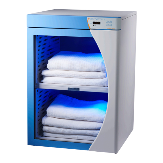
Titan & Comfort Series
Blanket Warmer
EC250
DC250
EC350
DC350
EC750
DC750
Table of
Contents
Previous
Page
Next
Page
1
2
3
4
5
Advertisement
Table of Contents
Need help?
Do you have a question about the Titan Series and is the answer not in the manual?
Ask a question
Questions and answers
Related Manuals for Enthermics Titan Series
Food Warmer Enthermics Titan & Comfort Series Operator's Manual
Blanket warmer (60 pages)
Food Warmer Enthermics DC250 Operation And Care Manual
Blanket warmer (44 pages)
Warming Drawer Enthermics DC150 Operation And Care Manual
Blanket warming cabinet (44 pages)
Food Warmer Enthermics DC250 Owner's Manual
Designer series blanket warmer (43 pages)
Food Warmer Enthermics EC250L Operator's Manual
Fluid warmer (56 pages)
Food Warmer Enthermics EC Series Owner's Manual
Fluid warmer (26 pages)
Food Warmer Enthermics EC Series Operation And Care Manual
Blanket warmer (25 pages)
Food Warmer Enthermics EC1260BL Owner's Manual
Combination warming cabinet 120v (30 pages)
Food Warmer Enthermics EC1350BL Operator's Manual
Combination blanket/fluid warmer (60 pages)
Food Warmer Enthermics EC1540 Owner's Manual
Blanket warmer (44 pages)
Food Warmer Enthermics Designer Series Operator's Manual
Blanket warmer (52 pages)
Food Warmer Enthermics ivNow-1 Owner's Manual
Fluid warmer (34 pages)
Food Warmer Enthermics EC2060 Operator's Manual
Blanket warmer (36 pages)
This manual is also suitable for:
Comfort series
Titan ec250
Titan ec350
Titan ec750
Titan dc250
Titan dc350
...
Show all
Titan dc750
Comfort ec250
Comfort ec350
Comfort ec750
Comfort dc250
Comfort dc350
Comfort dc750
Table of Contents
Save PDF
Print
Rename the bookmark
Delete bookmark?
Delete from my manuals?
Login
Sign In
OR
Sign in with Facebook
Sign in with Google
Upload manual
Upload from disk
Upload from URL


Need help?
Do you have a question about the Titan Series and is the answer not in the manual?
Questions and answers