Advertisement
Table of Contents
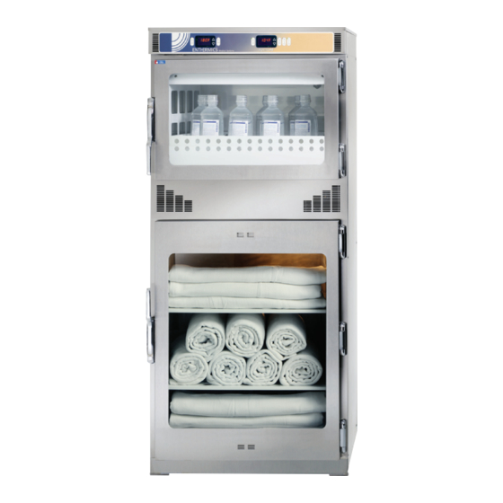
Combination Warming Cabinet
EC1260BL
Printed in the U.S.A.
Owner's Manual
EC1540BL
Specifications are subject to change without notice.
EC1730BL
Enthermics Medical Systems
An ISO 13485:2003 certified company
W164 N9221 Water St | Menomonee Falls WI 53051
Tel 262-251-8356 | 800-TO-B-WARM
EC1260BL
EC1540BL
EC1730BL
120V
generalinfo@enthermics com
www enthermics com
Made in the U.S.A.
MN-28646 • Rev 4 (03/18)
Advertisement
Table of Contents

Related Manuals for Enthermics EC1260BL


Summary of Contents for Enthermics EC1260BL
- Page 1 EC1260BL EC1540BL EC1730BL 120V EC1730BL EC1540BL EC1260BL Enthermics Medical Systems An ISO 13485:2003 certified company W164 N9221 Water St | Menomonee Falls WI 53051 Tel 262-251-8356 | 800-TO-B-WARM generalinfo@enthermics com www enthermics com Printed in the U.S.A. Specifications are subject to change without notice.
-
Page 2: Table Of Contents
Table of Contents Delivery Transportation Damage and Claims Unpacking Safety Procedures General Information Dimensions Electrical Information Operation Instructions Cleaning and Prevetative Maintenance Troubleshooting Service Wire Diagrams Refer to the wire diagram included with the appliance. Ent h er mi cs M ed i ca l Sy stem s - Th e Wa r m in g C o mpan y •... -
Page 3: Delivery
Enthermics will continue our policy of assisting our to the receiving area. Do not wait until a er the customers in collecting claims which have been properly appliance is moved to a storage area. -
Page 4: Unpacking
Unpacking 1. Carefully remove the appliance from the carton or crate. NOTE: Do not discard the carton and other packaging material until the appliance has been inspected for hidden damage and tested for proper operation. Do not discard this manual. This manual is considered to be part of the appliance and is to be provided to the owner or manager of the business or to the person responsible for training operators. -
Page 5: Safety Procedures
Safety Procedures • The blanket chamber is intended for warming dry, Knowledge of proper procedures is essential to the cotton blankets or towels only. The blanket chamber safe operation of electrically energized appliances. The is designed to elevate blanket temperatures to a level following hazard signal words and symbols may be used which will increase patient comfort. -
Page 6: General Information
4 digit L.E.D. display, available. ON/OFF button, INCREASE and DECREASE buttons, integrated lock-out control feature and a series of prompt EC1260BL INFORMATION: sequence indicators. The blanket warming chamber includes a white, epoxy- Each control can easily be set to operate in Fahrenheit or coated blanket support assembly and two (2) shelves. -
Page 7: Dimensions
Dimensions EC1260BL 4.10" (104.0mm) CORD 1.7" (43.0mm) CORD PIVOT 29.8" (756mm) RADIUS 21.7" (550mm) 30.1" (764mm) WITH HANDLE CORD LENGTH 0.5" 19.4" (493mm) 8' (2,438mm) (est.) (14mm) 12.5" (316mm) CAVITY 32.6" (827mm) CAVITY 17.3" (440mm) 0.6" (15mm) 26.6" (674mm) CAVITY... - Page 8 Dimensions EC1540BL 54.6" (1387mm) 7.5" (189mm) 11.2" (285mm) CORD LENGTH 8' (2,438mm) (est.) 17.1" 33.1" (841mm) (434mm) 22.1" (561mm) 35.1" (891mm) 28.9" (735mm) 22.3" (566mm) TIMER 9.8" (248mm) SHELF 16.9" (430mm) INSERT 5.5" (141mm) 18.7" (476mm) 26.6" (676mm) CAVITY CAVITY 25.2"...
- Page 9 Dimensions EC1730BL 4.0" (102mm) CORD LENGTH 8' (2,438mm) (est.) 4.6" (117mm) 27.1" (689mm) 25.4" (646mm) 30.2" (767mm) TIME START STOP ERROR TIMER OVER TEMP LOCK OVERTEMP LOCK 12.5" (318mm) CAVITY 32.5" (826mm) CAVITY 6.7" 24.6" (625mm) (171mm) INSERT 26.7" (678mm) 23.3"...
-
Page 10: Electrical Information
Do not load the metal basket beyond the recommended maximum capacity: Grounding reliability can only be achieved when equipment is EC1260BL = 18 1-liter bottles/basket or connected to an equivalent receptacle marked “Hospital Grade.” 28 1-liter bags/basket Safety Class I... -
Page 11: Operation Instructions
Operation Instructions Blanket Controller Settings Controller and LED 10 11 How to Set the Temperature Scale How to Lock the Controller 1. While the controller is in the o mode, press and hold The controller can be locked to prevent changes from the up arrow button for ve (5) seconds. - Page 12 Operation Instructions Blanket Controller Settings Controller and LED 10 11 How to Set the Timer . Press the "TIMER" button . The "TIME" icon illuminates. The controller displays the time of day in a 24-hour format (hh:mm). NOTE: If necessary, press the up arrow button or the down arrow button to change the current time of day.
- Page 13 Operation Instructions Operating the Blanket Chamber WARNING The blanket support assembly and shelf must be installed to prevent personal injury. NOTICE: The blanket support assembly and shelf must be installed to prevent blankets from scorching or discoloring. 1. Connect the warmer to an appropriate hospital grade Do not use blanket cleaning agents that cause receptacle —...
- Page 14 Operation Instructions Fluid Electronic Control Features The following refers to features that are available when the electronic control is powered on. Electronic Control and LED Display Status Status Error Main display Up arrow indicator LED set-point temperature indicator LED On/off Overtemp Lock Down...
- Page 15 Operation Instructions Fluid Chamber Operation Procedures WARNING Electronic Control and LED Display Status Indicator Error Main Display Status Verify the fluid temperature prior to using the fluid. Set-point Remperature Arrow Indicator LED Refer to fluid manufacturer’s labeling for recommended warming procedures. Injection fluid manufacturer suggests not to warm injection fluids above 40°C (104°F).
-
Page 16: Cleaning And Prevetative Maintenance
Cleaning and Prevetative Maintenance Cleaning and Preventive Maintenance Protecting stainless steel, epoxy coated and plastic Cleaning Materials surfaces Cleaning can usually be accomplished with the proper cleaning It is important to guard against corrosion agent and a so , clean cloth. When more aggressive methods are in the care of stainless steel surfaces. - Page 17 Cleaning and Preventative Maintenance WARNING WARNING To prevent serious personal injury, death, or To prevent serious injury, death, or property damage, always disconnect the appliance property damage: from the power source before cleaning Do not steam clean, hose down or flood the or servicing.
-
Page 18: Troubleshooting
Troubleshooting Notice: Do not attempt to repair or service the warmer This section is provided for the assistance of beyond this point. Contact the manufacturer for the qualified and trained service technicians only nearest authorized service agent. Repairs made by and is not intended for use by untrained or any other service agent without prior authorization unauthorized service personnel. - Page 19 • Inspect wires for integrity. Ensure proper and secure connections are made at the controller and the terminal block. • If the error continues call service. E-30 Under Temperature This error occurs when the blanket chamber temperature is lower than the set Troubleshooting (Blanket warmers temperature for 90 minutes or longer.
-
Page 20: Service
Service Full Assembly Service List DESCRIPTION EC1260BL EC1540BL EC1730BL INTERIOR FAN HOUSING/GUARD 1010254 1012557 1010844 FAN BLADE E3045FA FA-34603 E3045FA THERMOSTAT, MANUAL RESET, FLUID E3030TT TT-34644 E3030TT THERMOSTAT, MANUAL RESET, BLANKET TT-34600 TT-33476 TT-34600 SENSOR BLOCK BK-28344 BK-28344 BK-28344 SCREWS, SENSOR BLOCK (8-32 x 1" FH PHH) - Page 21 Service EC1260BL Full Assembly View MN-28646 • Rev 4 • 03/18 • EC Series Fluid Combination Blanket/Fluid Warmer...
- Page 22 Service EC1540BL Full Assembly View MN-28646 • Rev 4 • 03/18 • EC Series Fluid Combination Blanket/Fluid Warmer...
- Page 23 Service EC1730BL Full Assembly View MN-28646 • Rev 4 • 03/18 • EC Series Fluid Combination Blanket/Fluid Warmer...
- Page 24 † Note: The cavity fan motor has a one year life expectancy. The cavity fan motor parts warranty remains in eff ect one *NOT SHOWN (1) year from installation or fift een (15) months from the shipping date, whichever occurs first. EC1260BL Electrical View MN-28646 • Rev 4 • 03/18 • EC Series Fluid Combination Blanket/Fluid Warmer...
- Page 25 Service EC1540BL Electrical View EC1730BL Electrical View MN-28646 • Rev 4 • 03/18 • EC Series Fluid Combination Blanket/Fluid Warmer...
- Page 26 Service Accessory Service Parts List* *not shown ACCESSORY SERVICE PARTS LIST* *NOT SHOWN ACCESSORY SERVICE PARTS EC1260BL EC1540BL EC1730BL Built-in Trim Kit, Reach-In 5013968 5013889 5013968 Built-in Trim Kit, Pass-Through — — 5013968 (x2) Combination Lock reFer to combination locK manual MN-28753 Leg Kit Upgrade Kit, 6"...
-
Page 27: Wire Diagrams
Wire Diagrams Refer to wire diagram included with the unit. Serial number is required for all inquiries. Part numbers and drawings are subject to change without notice. MN-28646 • Rev 4 • 03/18 • EC Series Fluid Combination Blanket/Fluid Warmer... - Page 28 Wire Diagrams Refer to wire diagram included with the unit. Serial number is required for all inquiries. Part numbers and drawings are subject to change without notice. MN-28646 • Rev 4 • 03/18 • EC Series Fluid Combination Blanket/Fluid Warmer...
- Page 29 Wire Diagrams Refer to wire diagram included with the unit. Serial number is required for all inquiries. Part numbers and drawings are subject to change without notice. MN-28646 • Rev 4 • 03/18 • EC Series Fluid Combination Blanket/Fluid Warmer...
- Page 30 Enthermics Medical Systems An ISO 13485:2003 certified company W164 N9221 Water St | Menomonee Falls WI 53051 Tel 262-251-8356 | 800-TO-B-WARM generalinfo@enthermics.com www.enthermics.com Printed in the U.S.A. Specifications are subject to change without notice. Made in the U.S.A.
Need help?
Do you have a question about the EC1260BL and is the answer not in the manual?
Questions and answers