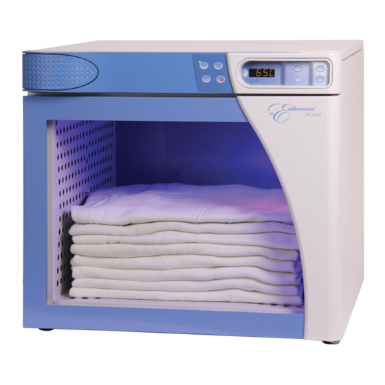
Enthermics Designer Series Operator's Manual
Blanket warmer
Hide thumbs
Also See for Designer Series:
- Operation and care manual (44 pages) ,
- Operation and care manual (44 pages)

Related Manuals for Enthermics Designer Series


Summary of Contents for Enthermics Designer Series
- Page 1 Operator’s Manual Designer Series Blanket Warmer DC150 DC400 MN-46427 REV.01 6/19...
-
Page 2: Manufacturer's Information
© Copyright 6/19 by Enthermics Medical Systems. All rights reserved. This manual or any portion thereof may not be reproduced or used in any manner whatsoever without the express written permission of Enthermics Medical Systems. Trademarks All trademarks referenced in this documentation are the property of their respective owners. -
Page 3: Foreword
Call 800-558-8744 to reach our 24-hour emergency service call center for immediate access to local authorized service agencies outside standard business hours. The emergency service access is provided exclusively for Enthermics Medical Systems equipment and is available throughout the United States through Enthermics toll free number. - Page 4 OREWORD This page intentionally left blank. B l an k e t W a rm e r Op er a to r ’ s Ma n u al M N- 46 4 2 7 Rev 1 6/ 1 9 ▪ ▪...
-
Page 5: Table Of Contents
Register Your Warmer ......3 Enthermics 24/7 Emergency Repair Service ....3 Safety The Meaning of Signal Words . - Page 6 OREWORD This page intentionally left blank. B l an k e t W a rm e r Op er a to r ’ s Ma n u al M N- 46 4 2 7 Rev 1 6/ 1 9 ▪ ▪...
-
Page 7: Safety
AFETY The Meaning of Signal Words This manual contains signal words where needed. These signal words must be obeyed to reduce the risk of death, personal injury, or equipment damage. The meaning of these signal words is explained below. DANGER Danger indicates a hazardous situation which, if not avoided, will result in serious injury or death. -
Page 8: Safety Precautions
AFETY Safety Precautions Before you begin Read and understand all instructions in this manual. Electrical precautions Obey these electrical precautions when using the warmer: ▪ Connect the warmer to a properly grounded outlet. Do not use the warmer if it is not properly grounded. - Page 9 (12) months by a trained technician. ▪ Contact Enthermics for the authorized service partner in your area. B la n k et W ar m er Op e r at or ’ s Man u a l...
- Page 10 AFETY This page intentionally left blank. B l an k e t W a rm e r Op er a to r ’ s Ma n u al M N- 46 4 2 7 Rev 1 6/ 1 9 ▪ ▪...
-
Page 11: Labels
ABELS Label Locations DC-PHD-007130 Bl a n k et W ar m er Op e r at or ’ s Man u a l MN -4 6 42 7 Re v 1 6 / 1 9 ▪ ▪ ▪ ▪... - Page 12 ABELS Security seal Electrical warning label Enthermics contact information Quality inspected B l an k e t W a rm e r Op er a to r ’ s Ma n u al M N- 46 4 2 7 Rev 1 6/ 1 9 ▪...
-
Page 13: Specifications
PECIFICATIONS Specification Information Model DC150 DC400 Net: 56 lb (25 kg) Net: 86 lb (39 kg) Weight Ship: 60 lb (27 kg) Ship: 144 lb (65 kg) 3–4 blankets 14–18 blankets Storage cavity (1.5 ft (4.0 ft capacity 90°F to 160°F (32°C to 71°C) Temperature range 3”... -
Page 14: Dimension Drawings
PECIFICATIONS Dimension Drawings DC150 shown with Standard Feet 9.2 " (235mm) IEC Cord Inlet Cord length: 6 ft (1.83m) (est.) 36.0 " (914mm) 22.7 " (577mm) 18.5 " (470mm) 20 " (508mm) 15.5 " (394mm) 14.4 " (366mm) CAVITY INSERT 14.5 "... - Page 15 PECIFICATIONS DC400 shown with Standard Feet 12 " (305mm) IEC Cord Inlet Cord length: 6 ft (1.83m) (est.) 47.0 " (1194mm) 28.0 " (712mm) 24.0 " (610mm) 25 " (635mm) 21 " (533mm) 20 " (507mm) CAVITY INSERT 21.0 " (533mm) 24.3 "...
- Page 16 PECIFICATIONS DC400 shown with Optional Plate and Casters 12 " (305mm) IEC Cord Inlet Cord length: 6 ft (1.83m) (est.) 47.0 " (1194mm) 28.0 " (712mm) 24.0 " (610mm) 25 " (635mm) 20 " (507mm) 21 " (533mm) INSERT CAVITY 21.0 "...
- Page 17 PECIFICATIONS DC400 shown with Optional Bumpers and Casters 13.4 " (339mm) IEC Cord Inlet Cord length: 6 ft (1.83m) (est.) 48.4 " (1229mm) 28.0 " (712mm) 24 " (610mm) 25 " (635mm) 21.0 " (533mm) 20 " (507mm) CAVITY INSERT 21.0 "...
- Page 18 PECIFICATIONS This page intentionally left blank. B l an k e t W a rm e r Op er a to r ’ s Ma n u al M N- 46 4 2 7 Rev 1 6/ 1 9 ▪ ▪...
-
Page 19: Installation
NSTALLATION How to Unpack the Warmer Before you begin you have: Make sure ▪ An appropriate lifting device and enough personnel to safely move and position the weight of the warmer. ▪ Cutting tools to remove the packaging. Unpack the warmer To unpack the warmer, do the following. -
Page 20: How To Install The Warmer
NSTALLATION How to Install the Warmer Before you begin you have: Make sure An appropriate lifting device and enough personnel to safely move and position the weight of the warmer. Requirements ▪ The warmer must be installed on a level surface. ▪... - Page 21 NSTALLATION Continued from previous page Connect power To connect electric power to the warmer, do the following. Connect the plug to the electrical outlet. NEMA 5-15P CEE 7/7 BS 1363 EC-TS-004411 Result The warmer is now installed and ready to be used. B la n k et W ar m er Op e r at or ’...
- Page 22 NSTALLATION This page intentionally left blank. B l an k e t W a rm e r Op er a to r ’ s Ma n u al M N- 46 4 2 7 Rev 1 6/ 1 9 ▪ ▪...
-
Page 23: Operation
PERATION Preparing the Warmer for First Use Before you begin CAUTION: Burn hazard. Allow the warmer to cool before cleaning. Do not use: NOTICE ▪ abrasive cleaning compounds. ▪ chloride based cleaners. ▪ commercial or household cleaners containing ammonia. ▪ cleaners containing quaternary salts. -
Page 24: How To Turn On And Turn Off The Warmer
PERATION How to Turn On and Turn Off the Warmer Before you begin The warmer must be connected to electric power. Turning on the To turn on the warmer, do the following. warmer Step Action the power switch to the ON (l) position. EC-TS-004545 Press the ON/OFF button... -
Page 25: How To Operate The Blanket Warmer
PERATION How to Operate the Blanket Warmer Before you begin The warmer must be connected to electric power and turned on. WARNING: Personal injury hazard. Do not operate the warmer in the presence of flammable anesthetic mixtures (with air or with oxygen or nitrous oxide). WARNING: Personal injury hazard. -
Page 26: How To Use The Timer (If Equipped)
PERATION How to Use the Timer (if equipped) Before you begin The warmer must be turned on (screen is on). Background The timer feature allows the user to program the controller to automatically turn on and off during a 24 hour period. This allows the warmer to turn off at night to save energy, then turn on automatically in the morning. - Page 27 PERATION Continued from previous page Setting the start To use the timer function, do the following. timer Step Action Press the Start Time button to view the start time for the day. Press and hold the Start Time button to set the current day’s start time as the same time for each day of the week.
- Page 28 PERATION Continued from previous page Setting different To set the timer for different start and stop times for each day of the week, do timer for each day of the following. the week Step Action Press and hold the Time button for eight (8) seconds.
-
Page 29: How To Change The Temperature Scale
PERATION How to Change the Temperature Scale Before you begin The warmer must be connected to electric power and the screen turned off. Procedure To change the temperature scale from °F to °C and vice versa, do the following. Step Action Press and hold the ON/OFF button... -
Page 30: How To Lock And Unlock The Controller
PERATION How to Lock and Unlock the Controller Before you begin The warmer must be turned on (screen is on). Background The controller can be locked to prevent changes being made to the temperature set-point. Locking the To lock the controller, do the following. controller Step Action... -
Page 31: How To Adjust The Interior Light
PERATION How to Adjust the Interior Light Before you begin The warmer must be turned on (screen is on). Procedure To adjust the interior light, do the following. Step Action Press the interior light button Press the interior light button again to adjust between the light settings. ... - Page 32 PERATION This page intentionally left blank. B l an k e t W a rm e r Op er a to r ’ s Ma n u al M N- 46 4 2 7 Rev 1 6/ 1 9 ▪ ▪...
-
Page 33: Maintenance
AINTENANCE Maintenance Schedule Daily For daily maintenance, do the following. Check: ▪ the air vents in the airflow insert panels are not obstructed (if applicable). ▪ all fan guards are clear and not obstructed (if applicable). ▪ the number of bottles/bags, or blankets as applicable do not exceed the maximum capacity per shelf or basket. -
Page 34: How To Clean The Warmer
AINTENANCE How to Clean the Warmer Before you begin WARNING: Electric shock hazard. Disconnect the warmer from electric power before cleaning. CAUTION: Burn hazard. Allow the warmer to cool before cleaning. Do not use: NOTICE ▪ abrasive cleaning compounds. ▪ chloride based cleaners. - Page 35 AINTENANCE Continued from previous page Yearly cleaning To clean the warmer yearly, do the following. procedure Step Action Make sure that the warmer is disconnected from electric power and cool. Remove the screws from the support assembly. Remove the support assembly from the interior of the warmer.
- Page 36 AINTENANCE This page intentionally left blank. B l an k e t W a rm e r Op er a to r ’ s Ma n u al M N- 46 4 2 7 Rev 1 6/ 1 9 ▪ ▪...
-
Page 37: Troubleshooting
ROUBLESHOOTING What to do if a Power Interruption Occurs Background You may need to reset the warmer in the case that a power interruption occurs. When the power is restored, the ON/OFF status indicator LED decimal flashes The controller stores all settings and continues operation using these settings in the event of a power interruption. -
Page 38: What To Do If The Alarm Indicator Light Flashes
ROUBLESHOOTING What to do if the Alarm Indicator Light Flashes Background The alarm indicator light flashes and the controller sounds an alarm when the warmer malfunctions. Procedure If the alarm indicator light flashes, do the following. Step Action Press the ON/OFF button to acknowledge and mute the alarm. -
Page 39: Error Codes
ROUBLESHOOTING Error Codes Background This section is provided for the assistance of qualified and trained service technicians only and is not intended for use by untrained or unauthorized service personnel. Failure to observe this precaution may void the warranty. NOTE: If the warmer is not operating properly, check the following before calling an authorized service agent:... - Page 40 ROUBLESHOOTING Code Refers to Action required E-11 Cavity sensor Sensor is open. Software disengages heating pads. Acknowledge error by ES11 Pad sensor 1 pressing the ON/OFF button. If error persists, a qualified service technician ES21 Pad sensor 2 should test the sensor. ES31 Pad sensor 3 ◾Test the sensor.
- Page 41 ROUBLESHOOTING Code Refers to Action required E-60 Real Time Clock Real time clock rechargeable battery backup has discharged. Checksum Error ◾Plug the warmer into the outlet for 30 minutes. (Blanket warmers only) *E-61 Real Time Clock Real time clock not responding. Contact service if error persists. (Blanket warmers only) E-62 Real Time Clock...
- Page 42 ROUBLESHOOTING Code Refers to Action required ◾Check to make sure the fan sensor wires did not disconnect from the fan *EFAn Fan or Fan Sensor Failure or the control board. ◾If the error persists after checking the wires, replace the fan. All non-critical codes can be cleared using the ON/OFF button.
-
Page 43: How To Replace A Fuse
ROUBLESHOOTING How to Replace a Fuse WARNING: Fire and electrical shock hazard. Use only UL listed 10A, 250V fast acting fuses, 5mm x 20mm (F1, F2). Access should be made by qualified service technicians only. Procedure To replace a fuse, do the following. Step Action Press and hold... - Page 44 ROUBLESHOOTING Continued from previous page Replace the fuse with a new fuse. Re-install the fuse drawer and fuse compartment cover. Result The fuse has now been replaced. B l an k e t W a rm e r Op er a to r ’ s Ma n u al M N- 46 4 2 7 Rev 1 6/ 1 9...
- Page 45 LECTRICAL NFORMATION Guidance and Manufacturer’s Declaration The warmer requires special precautions regarding EMC (Electromagnetic Compatibility) and needs to be installed and put into service according to the EMC information provided in the accompanying documents. Portable and mobile RF communications equipment can affect medical electrical equipment.
- Page 46 LECTRICAL NFORMATION Continued from previous page Electromagnetic The warmer is intended for use in the electromagnetic environment specified immunity below. Immunity test IEC 60601 test level Compliance level Electromagnetic environment - guidance Electromagnetic ±8 kV contact ±8 kV contact Floors should be wood, concrete or ceramic discharge (ESD) tile.
-
Page 47: Electrical Information
LECTRICAL NFORMATION Continued from previous page Electromagnetic The warmer is intended for use in the electromagnetic environment specified emissions below. Immunity test IEC 60601 test level Compliance level Electromagnetic environment - guidance Conducted RF 3 V/m 3 V/m Portable and mobile RF communications IEC 61000-4-6 150 kHz to 80 MHz equipment should be used no closer to any... - Page 48 LECTRICAL NFORMATION Continued from previous page Electromagnetic The warmer is intended for use in an electromagnetic environment in which immunity distance radiated RF disturbances are controlled. The user of the warmer can help prevent electromagnetic interference by maintaining a minimum distance between portable and mobile RF communications equipment (transmitters) and the warmer as recommended below, according to the maximum output power of the communications equipment.
-
Page 49: Warranty
Enthermics Medical Systems warrants to the original purchaser only, that any original part found to be defective in material or workmanship will be replaced with a new or rebuilt part at Enthermics option, subject to provisions hereinafter stated. Warranty Period The original parts warranty period is as follows: ▪... - Page 50 No person except an officer of Enthermics is authorized to modify this warranty or to incur on behalf of Enthermics any other obligation or liability in connection with Enthermics equipment.
- Page 52 Enthermics Medical Systems AN ISO 13485:2016 certified company W164 N9221 Water St Menomonee Falls, WI 53051 262-251-8356 | 800-TO-B-WARM generalinfo@enthermics.com www.enthermics.com Printed in the U.S.A. Specifications are subject to change without notice. Made in the U.S.A...