Enthermics DC150 Operation And Care Manual
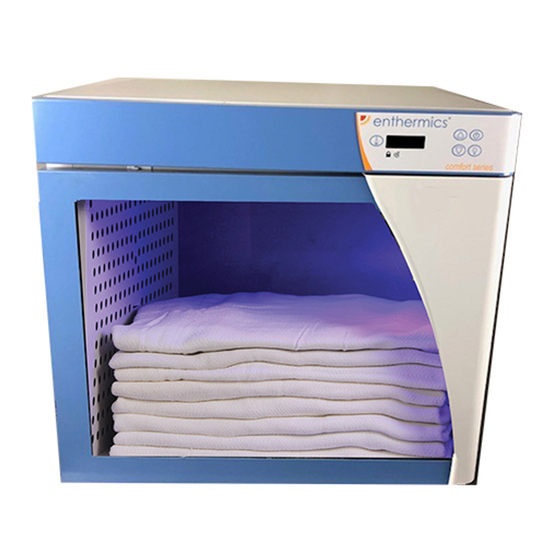
Blanket warming cabinet
Hide thumbs
Also See for DC150:
- Owner's manual (43 pages) ,
- Operation and care manual (44 pages) ,
- Operator's manual (52 pages)
Table of Contents
Advertisement
Operation and Care Manual
Blanket Warming Cabinet
DC150
(shown with optional timer)
(shown with optional timer)
.
.
.
P R I N T E D I N U
S
A
Designer Series
DC350
DC250
DC400
S P E C I F I C A T I O N S A R E S U B J E C T T O C H A N G E W I T H O U T N O T I C E
DC750
(shown with optional timer)
W164 N9221 Water St, Menomonee Falls WI 53051
DC150
DC250
DC350
DC400
DC750
ENTHERMICS MEDICAL SYSTEMS
An ISO 13485:2003 certified company
PO Box 443, Menomonee Falls WI 53052-0443
Tel 262-251-8356 | 800-TO-B-WARM
generalinfo@enthermics .com
www .enthermics .com
M A D E I N T H E U
M N - 3 7 0 7 2 R e v 1 ( 0 7 / 1 5 )
.
.
.
S
A
Advertisement
Table of Contents

Related Manuals for Enthermics DC150


Summary of Contents for Enthermics DC150
- Page 1 DC750 DC750 (shown with optional timer) DC400 (shown with optional timer) ENTHERMICS MEDICAL SYSTEMS An ISO 13485:2003 certified company PO Box 443, Menomonee Falls WI 53052-0443 W164 N9221 Water St, Menomonee Falls WI 53051 Tel 262-251-8356 | 800-TO-B-WARM generalinfo@enthermics .com www .enthermics .com...
-
Page 2: Table Of Contents
DC150 . . . . . . . . . . . . . . . . . . . . -
Page 3: Environmental Conditions
D A M A G E & C L A I M S All Enthermics Medical Systems equipment 3 . Note all damage to packages directly on the carrier’s is sold F .O .B . shipping point, and when delivery receipt . -
Page 4: Unpacking
U N P A C K I N G A N D S E T - U P • Carefully remove the appliance from the carton (A) or crate (B) NOTICE: Do not discard the carton and other packaging material until you have inspected the unit for hidden damage and tested it for proper operation . -
Page 5: Safety Procedures And Precautions
S A F E T Y P R O C E D U R E S A N D P R E C A U T I O N S Knowledge of proper procedures is essential to the safe 1 . This blanket warmer is intended for warming DRY, cotton operation of electrically energized equipment . -
Page 6: Preparation
Hazardous 2 .5 ft Capacity 1 .5 ft acity Voltage Present 67 lbs (30 kg) 135 lbs (62 kg) Weight** (est.) DC150 DC250 56 lbs (25 kg) 118 lbs (54 kg) ght** (est.) SHIP CRATED SHIP CRATED 120 V .A .C . — 60 Hz, 1 ph... -
Page 7: General Information
E L E C T R I C A L I N F O R M A T I O N D A N G E R D A N G E R TO PREVENT SERIOUS INJURY, Ensure power source matches DEATH, OR PROPERTY DAMAGE: voltage identified on appliance rating DO NOT use this warming appliance... -
Page 8: Dc150
D I M E N S I O N S DC150 Dimensions (HxWxD) 17 .0" x 18 .5" x 22 .7" (431mm x 470mm x 577mm) With feet (standard): 20 .5" x 18 .5" x 22 .7" (521mm x 470mm x 577mm) With casters (optional): 1 .5 ft... - Page 9 D I M E N S I O N S DC150 (continued) 9.2 " (235mm) IEC Cord Inlet Cord length: 6 ft (1.83m) (est.) 36.0" (914mm) 22.7" (577mm) 18.5" (470mm) 19.8" (504mm) 15.5" (394mm) 14.4" (366mm) CAVITY INSERT 14.5" (368mm) 20.0"...
-
Page 10: Dc250
D I M E N S I O N S DC250 Dimensions (HxWxD) 21 .9" x 18 .5" x 25 .7" (557mm x 470mm x 653mm) With feet (standard): With plate and 26 .2" x 18 .5" x 25 .7" (666mm x 470mm x 653mm) casters (optional): With bumper and 26 .3"... - Page 11 D I M E N S I O N S DC250 (continued) 9.3 " (235mm) IEC Cord Inlet CORD LENGTH: 6 ft (1.83m) (est.) 36.0" (914mm) 25.7" (653mm) 22.8" (580mm) 18.5" (470mm) 14.5" (369mm) 18.6" (472mm) INSERT CAVITY 15.5" (394mm) 22.2"...
- Page 12 D I M E N S I O N S DC250 (continued) 10.6" (270mm) IEC Cord Inlet CORD LENGTH: 6 ft (1.83m) (est.) 37.4" (949mm) 25.7" (653mm) 22.8" (580mm) 18.5" (470mm) 14.5" (369mm) 18.6" (472mm) INSERT CAVITY 15.5" (394mm) 25.1" (631mm) CAVITY 25.9"...
- Page 13 D I M E N S I O N S DC250 (continued) 9.3 " (235mm) IEC Cord Inlet CORD LENGTH: 6 ft (1.83m) (est.) 36.0" (914mm) 25.7" (653mm) 22.8" (580mm) 18.5" (470mm) 14.5" (369mm) 18.6" (472mm) INSERT CAVITY 15.5" (394mm) 22.2"...
-
Page 14: Dc350
D I M E N S I O N S DC350 Dimensions (HxWxD) 27 .9" x 18 .5" x 25 .7" (709mm x 470mm x 653mm) With feet (standard): With plate and 32 .2" x 18 .5" x 25 .7" (819mm x 470mm x 653mm) casters (optional): With bumper and 32 .2"... - Page 15 D I M E N S I O N S DC350 (continued) 9.3 " (235mm) IEC Cord Inlet Cord length: 6 ft (1.83m) (est.) 36.0" (914mm) 25.7" (653mm) 22.8" (580mm) 18.5" (470mm) 18.5" (470mm) CAVITY 14.5" (369mm) INSERT 22.2" (563mm) 15.5"...
- Page 16 D I M E N S I O N S DC350 (continued) 10.6 " (270mm) IEC Cord Inlet Cord length: 6 ft (1.83m) (est.) " 37.3 (948mm) 25.7" (653mm) 22.8" (580mm) 18.5" (470mm) 18.5" (470mm) CAVITY 14.5" (369mm) INSERT 15.5" (394mm) 25.1"...
- Page 17 D I M E N S I O N S DC350 (continued) 9.3 " (235mm) IEC Cord Inlet Cord length: 6 ft (1.83m) (est.) 36.0" (914mm) 25.7" (653mm) 22.8" (580mm) 18.5" (470mm) 18.5" (470mm) CAVITY 14.5" (369mm) INSERT 22.2" (564mm) 15.5"...
-
Page 18: Dc400
D I M E N S I O N S DC400 Dimensions (HxWxD) 21 .9" x 24" x 28" (557mm x 610mm x 712mm) With feet (standard): With plate and 26 .1" x 24" x 28" (664mm x 610mm x 712mm) casters (optional): With bumper and 26 .2"... - Page 19 D I M E N S I O N S DC400 (continued) 12 " (305mm) IEC Cord Inlet Cord length: 6 ft (1.83m) (est.) 47.0" (1194mm) 28.0" (712mm) 24.0" (610mm) 25.1" (638mm) 20" (507mm) 21" (533mm) INSERT CAVITY 21.0" (533mm) 24.4"...
- Page 20 D I M E N S I O N S DC400 (continued) 13.4 " (339mm) IEC Cord Inlet Cord length: 6 ft (1.83m) (est.) 48.4" (1229mm) 28.0" (712mm) 24" (610mm) 25.1" (638mm) 21.0" (533mm) 20" (507mm) CAVITY INSERT 21.0" (533mm) 27.4"...
- Page 21 D I M E N S I O N S DC400 (continued) 12 " (305mm) IEC Cord Inlet 47.0" (1194mm) 28.0" (712mm) 24.0" (610mm) 25.1" (638mm) 20" (507mm) 21" (533mm) INSERT CAVITY 21.0" (533mm) 24.4" (621mm) CAVITY with optional casters M N - 3 707 2 R ev 1 (0 7/ 15 ) •...
-
Page 22: Dc750
D I M E N S I O N S DC750 Dimensions (HxWxD) 35 .4" x 24 .0" x 28 .0" (900mm x 610mm x 710mm) With feet (standard): With plate and 39 .3" x 24 .0" x 28 .0" (997mm x 610mm x 710mm) casters (optional): With bumper and 39 .3"... - Page 23 D I M E N S I O N S DC750 (continued) 12.0 " (305mm) IEC Cord Inlet Cord length: 6 ft (1.83m) (est.) 47.0" (1194mm) 28.0" (710mm) 25.1" (637mm) 24.0" (610mm) 21.0" (533mm) CAVITY 19.9" (506mm) INSERT 21.0" (533mm) 18.7"...
- Page 24 D I M E N S I O N S DC750 (continued) 13.4" (340mm) IEC Cord Inlet Cord length: 6 ft (1.83m) (est.) 48.3" (1228mm) 28.0" (712mm) 24.0" (610mm) 25.1" (637mm) 21.0" (533mm) CAVITY 19.9" (506mm) INSERT 21.0" (533mm) 27.4" (695mm) CAVITY 26.8"...
- Page 25 D I M E N S I O N S DC750 (continued) 12.0 " (305mm) IEC Cord Inlet Cord length: 6 ft (1.83m) (est.) 47.0" (1194mm) 28.0" (710mm) 25.1" (637mm) 24.0" (610mm) 21.0" (533mm) CAVITY 19.9" (506mm) INSERT 21.0" (533mm) 25.2"...
-
Page 26: General Warnings
G E N E R A L W A R N I N G S WARNING The unit requires special precautions regarding EMC A risk of increased emissions or decreased immunity (Electromagnetic Compatibility) and needs to be installed may result if the power cord attached is altered or a and put into service according to the EMC information manufacturer supplied power cable is not used. - Page 27 Guidance and manufacturer’s declaration - electromagnetic emissions The unit is intended for use in the electromagnetic environment specifi ed below. The customer or the end user of this unit should assure that it is used in such an environment. Compliance IEC 60601 test Immunity test Electromagnetic environment - guidance...
-
Page 28: Blanket Control Features
B L A N K E T C O N T R O L F E A T U R E S Temperature Range: Control and LED Display 32°-72° C (90°-160°F) ON/OFF TEMPERATURE button button RECALL button Button lockout Error DOWN INTERIOR indicator light... -
Page 29: Optional Features
O P T I O N A L F E A T U R E – T I M E R C O N T R O L 4. Press the UNIT TIME button again to set the date. Optional Timer Control Press the UP or DOWN button to adjust the date. -
Page 30: Operation Procedures
B L A N K E T C H A M B E R O P E R A T I O N P R O C E D U R E S The appliance should be plugged into an appropriate hospital grade receptacle as specifi... -
Page 31: Protecting Stainless Steel Surfaces
C L E A N I N G A N D P R E V E N T I V E M A I N T E N A N C E PROTECTING STAINLESS STEEL, EPOXY COATED AND CLEANING MATERIALS PLASTIC SURFACES Cleaning can usually be accomplished with the proper cleaning It is important to guard against corrosion... -
Page 32: Clean The Unit Regularly
C A R E A N D C L E A N I N G CLEAN THE UNIT REGULARLY: 1. Disconnect the cabinet from the power source. 4. Interior can be wiped with a sanitizing solution after cleaning and rinsing. This solution must be approved 2. -
Page 33: Troubleshooting Guide
T R O U B L E S H O O T I N G G U I D E NOTICE: If your unit is not operating properly, check the following before calling your authorized service agent. Check the power applied to the unit. -
Page 34: Fuse Replacement
*E-81 Calibration Call service not locked *E-83 EEPROM Error Call service for help resetting the control. E-87 EEPROM Error Stored offsets corrupted. Offsets reset to 0. Control may need to be recalibrated. Possible bad EEPROM. Call service if error persists. T R O U B L E S H O O T I N G G U I D E S E R V I C E E-90... -
Page 35: Options & Accessories
Equipment on casters can move or roll on uneven fl oors. DC150 on 5018614 Cart DC400 over DC750 SERIAL NUMBER IS REQUIRED FOR ALL INQUIRIES PART NUMBERS AND DRAWINGS ARE SUBJECT TO CHANGE WITHOUT NOTICE. -
Page 36: Full Assembly Service View
S E R V I C E FULL ASSEMBLY A Item Description Part Item Description Part S IDE COVER, 1.5ft 1011024 2 REAR COVER, STAINLESS STEEL, 1.5ft 1014262 1 SIDE COVER, STAINLESS STEEL, 1.5ft 1014261 2 REAR COVER, 2.5ft 5013521 1 SIDE COVER, 2.5ft 1011269 2 REAR COVER, STAINLESS STEEL, 2.5ft... - Page 37 S E R V I C E FULL ASSEMBLY B Item Description Part Item Description Part BLANKET SUPPORT BOTTOM, 1.5ft 1011045 DOOR ASSEMBLY, PAINTED W/ LOCK, 1.5ft 5018255 BLANKET SUPPORT BOTTOM, 2.5ft 1011265 DOOR ASSEMBLY, STAINLESS STEEL W/ LOCK, 1.5ft 5018260 BLANKET SUPPORT BOTTOM, 3.5ft 1011265...
- Page 38 S E R V I C E FULL ASSEMBLY C Item Description Part Item Description Par t CHASSIS, 3-ZONE, 120V, 1.5ft /2.5ft 5017792 SPRING, DOOR, 1.5ft SD-29340 CHASSIS, 3-ZONE, 230V, 1.5ft /2.5ft 5017795 SPRING, DOOR, 2.5ft /3.5ft /4.0ft /7.5ft SD-29467 CHASSIS, 4-ZONE, 120V, 3.5ft /4.0ft /7.5ft...
-
Page 39: Electrical Chassis Service View
S E R V I C E ELECTRICAL CHASSIS Item Description Part WIRE ASSEMBLY, CONTROL, ALL VERSIONS, 5018056 NOT SHOWN POWER SUPPLY, 20W BA-34965 1 RELAY BOARD, 3-ZONE, 120V, 1.5ft /2.5ft BA-35106 1 RELAY BOARD, 4-ZONE, 120V, 3.5ft /4.0ft /7.5ft BA-35107 1 RELAY BOARD, 3-ZONE, 230V, 1.5ft /2.5ft... -
Page 40: Door Latch & Sensor Service View
S E R V I C E DOOR LATCH & SENSOR Item Description Part PLATE, LATCH PULL, 1.5ft 1011197 PLATE, LATCH PULL, 2.5ft /4.0ft 1011263 PLATE, LATCH PULL, 3.5ft 1011295 PLATE, LATCH PULL, 7.5ft 1011850 GUIDE, LOW PROFILE RAIL, 1.5ft GI-29204 GUIDE, LOW PROFILE RAIL, 2.5ft /3.5ft... -
Page 41: Control Interface Service View
S E R V I C E CONTROL INTERFACE Item Description Part PANEL, INTERFACE MOUNT, 18.5", 1.5ft /2.5ft /3.5ft 1011336 PANEL, INTERFACE MOUNT, 24", 4.0ft /7.5ft 1011482 PANEL, FRONT TOP TRIM, PAINTED, 18.5", 1.5ft /2.5ft /3.5ft 1011032 PANEL, FRONT TOP TRIM, PAINTED, 24", 4.0ft /7.5ft 1011481 PANEL, FRONT TOP TRIM, STAINLESS STEEL, 18.5", 1.5ft... -
Page 42: Shelf (Dc350/Dc750) Service View
S E R V I C E SHELF (DC350/DC750 only) Item Description Part PANEL, HEATED SHELF BOTTOM, 3.5ft 1011230 PANEL, HEATED SHELF BOTTOM, 7.5ft 1011597 PANEL, HEAT SHELF, 3.5ft 1015078 PANEL, HEATED SHELF, 7.5ft 1014609 HEATED SHELF KIT, 3.5ft 5017020 HEATED SHELF KIT 5019545 LED ASSEMBLY... - Page 43 Refer to wire diagram included with the unit. M N - 3 7 07 2 R ev 1 (0 7 /15 ) • E nth e rm i cs D es i gn e r Se ri e s B la n ke t Wa rm i n g C a bi n et • 41...
- Page 44 ENTHERMICS MEDICAL SYSTEMS An ISO 13485:2003 certified company PO Box 443, Menomonee Falls WI 53052-0443 W164 N9221 Water St, Menomonee Falls WI 53051 Tel 262-251-8356 | 800-TO-B-WARM generalinfo@enthermics.com www.enthermics.com P R I N T E D I N U M A D E I N T H E U...
Need help?
Do you have a question about the DC150 and is the answer not in the manual?
Questions and answers