
Related Manuals for Enthermics EC1350BL


Summary of Contents for Enthermics EC1350BL
- Page 1 Operator’s Manual Combination Blanket/Fluid Warmer EC1350BL EC1850BL MN-39940 REV.03 8/20...
-
Page 2: Manufacturer's Information
© Copyright 8/20 by Enthermics Medical Systems. All rights reserved. This manual or any portion thereof may not be reproduced or used in any manner whatsoever without the express written permission of Enthermics Medical Systems. Trademarks All trademarks referenced in this documentation are the property of their respective owners. -
Page 3: Foreword
Call 800-558-8744 to reach our 24-hour emergency service call center for immediate access to local authorized service agencies outside standard business hours. The emergency service access is provided exclusively for Enthermics Medical Systems equipment and is available throughout the United States through Enthermics toll free number. - Page 4 OREWORD This page intentionally left blank. Co m b i n at i on B l an k e t/ F l u id W a rm e r Op er a to r ’ s Ma n u al M N- 39 9 4 0 Rev 3 8/ 2 0...
-
Page 5: Table Of Contents
Register Your Warmer ......3 Enthermics 24/7 Emergency Repair Service ....3 Safety The Meaning of Signal Words . - Page 6 OREWORD Warranty Warranty ........57 Co m b i n at i on B l an k e t/ F l u id W a rm e r Op er a to r ’...
-
Page 7: Safety
AFETY The Meaning of Signal Words This manual contains signal words where needed. These signal words must be obeyed to reduce the risk of death, personal injury, or equipment damage. The meaning of these signal words is explained below. DANGER Danger indicates a hazardous situation which, if not avoided, will result in serious injury or death. -
Page 8: Safety Precautions
Inspection and servicing of internal components must only be performed by qualified service personnel. ▪ Only a qualified Enthermics service representative may make modifications to the warmer. Modifications to the warmer could be hazardous to users and patients. Operator training All personnel using the warmer must have proper operator training. - Page 9 To prevent serious injury, death or property damage, have the warmer inspected and serviced at least every twelve (12) months by a trained technician. ▪ Contact Enthermics for the authorized service partner in your area. ▪ Incident notice Any serious incident that has occurred in relation to the warmer should be reported to the manufacturer and the competent authority of the Member State in which the user and/or patient is established.
- Page 10 AFETY This page intentionally left blank. Co m b i n at i on B l an k e t/ F l u id W a rm e r Op er a to r ’ s Ma n u al M N- 39 9 4 0 Rev 3 8/ 2 0...
-
Page 11: Labels
Label Locations EC1350BL Reach-In EC1850BL EC1350BL Pass-Through (Top View) EC-PHD-004613 Co m bi n a ti o n B l an k et / Fl u i d W ar m er Ope r at or ’ s Man u a l... - Page 12 ABELS Security seal EC1350BL Electrical warning label EC1850BL Electrical warning label Enthermics contact information Quality inspected WARNING Hot surface — (label installed on the interior cavity wall) Co m b i n at i on B l an k e t/ F l u id W a rm e r Op er a to r ’...
-
Page 13: Specifications
1” (51mm) from sides 2” (51mm) from sides Clearance 1/2” (13mm) from bottom requirements NOTE: See topic Dimension Drawings for EC1350BL Built- In requirements. Transportation and ▪ Ambient temperature range of -40°F to +159°F (-40°C to +70°C). storage conditions ▪... -
Page 14: Dimension Drawings
PECIFICATIONS Dimension Drawings EC1350BL Reach-In 59.5 " (1511mm) 21.25 " (539.75mm) 19.75 " (501.75mm) " (763mm) 26.5 " (673mm) " (432mm) CAVITY CAVITY 26.5 " (673mm) 17" (432mm) CAVITY CAVITY EC-DIM-008782 Co m b i n at i on B l an k e t/ F l u id W a rm e r Op er a to r ’... - Page 15 PECIFICATIONS EC1350BL Pass-Through 59.5 " (1511mm) 59.5 " (1511mm) 21.25 " (539.75mm) " (763mm) 19.75 " (501.75mm) 26.5 " (673mm) " (432mm) CAVITY CAVITY 26.5 " (673mm) " (432mm) CAVITY CAVITY EC-DIM-008789 Co m bi n a ti o n B l an k et / Fl u i d W ar m er Ope r at or ’...
- Page 16 PECIFICATIONS EC1350BL Built-In 59.5 " (1511mm) 21.25 " (539.75mm) 19.75 " (501.75mm) " (763mm) 26.5 " (673mm) " (432mm) CAVITY CAVITY 26.5 " (616mm) " (432mm) CAVITY CAVITY EC-DIM-008794 Co m b i n at i on B l an k e t/ F l u id W a rm e r Op er a to r ’...
- Page 17 PECIFICATIONS EC1350BL Built-In Cutout Specifications and Inlet Locations CAUTION: Fire hazard. Supply wires must be rated for a minimum wire temperature of 80°C. NOTICE Built-in units must be hardwired to the facility mains with a 20A breaker switch. Breaker* Wire Size**...
- Page 18 PECIFICATIONS Continued from previous page 7.75 " (196mm) " (89mm) 29.25 " (743mm) 7.25 " (184.25mm) " (432mm) EC-DIM-008799 Co m b i n at i on B l an k e t/ F l u id W a rm e r Op er a to r ’...
- Page 19 PECIFICATIONS EC1850BL shown with feet " 58.75 (1492mm) " 28.25 (715mm) " 26.5 (673mm) " (763mm) " " 26.5 (673mm) 23.75 (603mm) CAVITY CAVITY " 23.60 (598mm) INSERT " 23.60 (598mm) INSERT " 23.75 (603mm) CAVITY EC-DIM-004602 Co m bi n a ti o n B l an k et / Fl u i d W ar m er Ope r at or ’...
- Page 20 PECIFICATIONS EC1850BL shown with casters 58.75 " (1492mm) 28.5 " (721mm) 26.5 " (673mm) " (763mm) 26.5 " (673mm) 23.75 " (603mm) CAVITY CAVITY 23.60 " (598mm) INSERT 23.60 " (598mm) INSERT 23.75 " (603mm) CAVITY EC-DIM-004605 Co m b i n at i on B l an k e t/ F l u id W a rm e r Op er a to r ’...
-
Page 21: Installation
NSTALLATION How to Unpack the Warmer WARNING: Crushing hazard. An unstable warmer can lead to a crushing hazard. Observe your facility’s best practices for moving large equipment. Before you begin Make sure you have: ▪ Reviewed the warmer specifications. ▪ An appropriate lifting device and enough personnel to safely move and position the weight of the warmer. - Page 22 NSTALLATION Continued from previous page EC1350BL only Open the accessories box and install the shelf clips and shelves into the cavities. NOTE: Set aside the toe panel(s) and screws. The toe panel(s) and screws will be used during installation after mounting the warmer.
-
Page 23: How To Install The Warmer
NSTALLATION How to Install the Warmer WARNING: Tipping hazard. Mount the EC1350BL to the floor before use. Before you begin you have: Make sure An appropriate lifting device and enough personnel to safely move and position the weight of the warmer. - Page 24 Mount the warmer to To mount the warmer to the floor, do the following. floor (EC1350BL only) WARNING: Tipping hazard. Mount the EC1350BL to the floor before use. NOTE: Reference OPM-0562-19 for California seismic conformance. Bolt the warmer to the floor.
- Page 25 NSTALLATION Continued from previous page Install the toe panel. EC-TS-009347 Connect power To connect electric power to the warmer, do the following. Connect the plug to the electrical outlet. NOTE: For built-in units, contact a licensed contractor or electrician for connection to facility power. Result The warmer is now installed and ready to be used.
- Page 26 NSTALLATION This page intentionally left blank. Co m b i n at i on B l an k e t/ F l u id W a rm e r Op er a to r ’ s Ma n u al M N- 39 9 4 0 Rev 3 8/ 2 0...
-
Page 27: Operation
PERATION Preparing the Warmer for First Use Before you begin CAUTION: Burn hazard. Allow the warmer to cool before cleaning. Do not use: NOTICE ▪ abrasive cleaning compounds. ▪ chloride based cleaners. ▪ commercial or household cleaners containing ammonia. ▪ Approved cleaning 70% or greater isopropyl alcohol agents... -
Page 28: How To Turn On And Turn Off The Warmer
To turn on the warmer, do the following. warmer Step Action the power switch to the ON (l) position. EC1350BL EC1850BL EC-TS-004628 Press the standby button . The screen turns on. The blanket warmer and TriMode warmer screens must be turned ON separately. - Page 29 PERATION Continued from previous page Turning off the To turn off the warmer, do the following. warmer Press and hold the standby button until the screen turns off. The blanket warmer and TriMode warmer screens must be turned OFF separately. The warmer is now off.
-
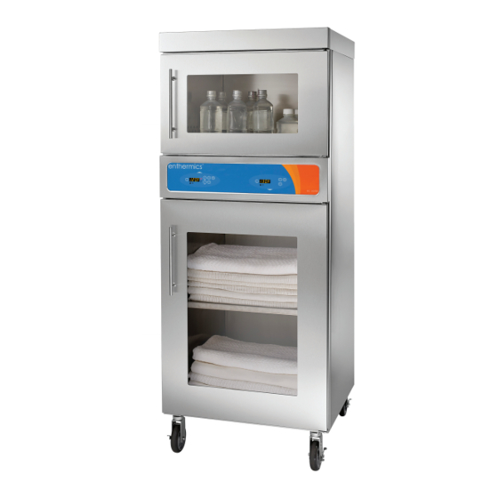
Page 30: How To Operate The Blanket Warmer (Bottom Cavity)
PERATION How to Operate the Blanket Warmer (Bottom Cavity) Before you begin The warmer must be connected to electric power and turned on. WARNING: Personal injury hazard. Do not operate the warmer in the presence of a flammable anesthetic mixture with air, oxygen, or nitrous oxide; in oxygen-enriched environments;... -
Page 31: How To Operate The Trimode Warmer (Top Cavity)
PERATION How to Operate the TriMode Warmer (Top Cavity) Before you begin The warmer must be connected to electric power and turned on. WARNING: Personal injury hazard. Do not operate the warmer in the presence of a flammable anesthetic mixture with air, oxygen, or nitrous oxide; in oxygen-enriched environments;... - Page 32 PERATION Continued from previous page the temperature using the arrow buttons NOTE: The irrigation temperature set-point range is 90°F – 150°F (32°C – 66°C). The injection temperature set-point range is 90°F – 104°F (32°C – 40°C). The blanket temperature set-point range is 90°F – 160°F (32°C –...
-
Page 33: How To Change The Temperature Scale
PERATION How to Change the Temperature Scale Before you begin The warmer must be connected to electric power and the screen turned off. Procedure To change the temperature scale from °F to °C and vice versa, do the following. Step Action Press and hold the standby button... -
Page 34: How To Lock And Unlock The Controller
PERATION How to Lock and Unlock the Controller Before you begin The warmer must be turned on (screen is on). Background The controller can be locked to prevent changes being made to the temperature set-point. Locking the To lock the controller, do the following. controller Step Action... -
Page 35: How To Download Temperature Data From The Warmer
PERATION How to Download Temperature Data from the Warmer Before you begin ▪ The warmer must be turned on (screen is on). ▪ Do not remove the USB drive during the download process. ▪ You will need a SanDisk Cruzer Glide USB drive. NOTICE Only use a SanDisk Cruzer Glide USB drive larger than 4 GB. - Page 36 PERATION Continued from previous page Plug the USB drive into the port . The warmer downloads the temperature data. NOTICE Do not remove the USB drive during the download process. EC-TS-005823 The warmer goes through the download process: The LED screen located above the USB port flashes for a few seconds to ▪...
- Page 37 PERATION Continued from previous page Viewing data in The table below is an example of temperature data from the warmer. Microsoft® Excel Time Stamp Chamber Mode Power Door Temperature Set-point Errors 12/19/2018 14:48 bottom closed 71.7 Diagnostics.SensorSho rtErrors=0x0c 12/19/2018 14:48 closed 71.2 Diagnostics.SensorSho...
- Page 38 PERATION This page intentionally left blank. Co m b i n at i on B l an k e t/ F l u id W a rm e r Op er a to r ’ s Ma n u al M N- 39 9 4 0 Rev 3 8/ 2 0...
-
Page 39: Maintenance
AINTENANCE Maintenance Schedule NOTE: Do not remove exterior panels from the warmer or attempt repairs. The warmer has no user-serviceable internal components. Only perform routine cleaning and maintenance procedures specifically described in this manual. Daily For daily maintenance, do the following. Check: ▪... - Page 40 AINTENANCE Continued from previous page Yearly For yearly maintenance, do the following. Check: ▪ the set-point temperature compared to the actual temperature displayed. Check the cavity air temperature with a thermocouple placed 1” (25mm) from □ the cavity sensor. Do not allow the thermocouple to touch any surface. Monitor the temperature for approximately one hour in an empty cavity.
-
Page 41: How To Clean The Warmer
AINTENANCE How to Clean the Warmer Before you begin WARNING: Electric shock hazard. Disconnect the warmer from electric power before cleaning. WARNING: Crushing hazard. An unstable warmer can lead to a crushing hazard. Observe your facility’s best practices for moving large equipment. CAUTION: Burn hazard. - Page 42 AINTENANCE Continued from previous page Yearly cleaning To clean the warmer yearly, do the following. procedure Step Action Make sure that the warmer is disconnected from electric power and cool. Remove the shelves from the interior of the warmer. EC-TS-004655 Remove the side panels from the interior of the blanket warmer cavity.
-
Page 43: Warmer Disposal / Decommissioning
AINTENANCE Warmer Disposal / Decommissioning This product and its accessories must be disposed of according to local laws and regulations. Do not dispose of this product as unsorted municipal waste. Co m bi n a ti o n B l an k et / Fl u i d W ar m er Ope r at or ’... - Page 44 AINTENANCE This page intentionally left blank. Co m b i n at i on B l an k e t/ F l u id W a rm e r Op er a to r ’ s Ma n u al M N- 39 9 4 0 Rev 3 8/ 2 0...
-
Page 45: Troubleshooting
ROUBLESHOOTING What to do if a Power Interruption Occurs Background You may need to reset the warmer in the case that a power interruption occurs. When the power is restored, the ON/OFF status indicator LED decimal flashes The controller stores all settings and continues operation using these settings in the event of a power interruption. -
Page 46: What To Do If The Alarm Indicator Light Flashes
ROUBLESHOOTING What to do if the Alarm Indicator Light Flashes Background The alarm indicator light flashes and the controller sounds an alarm when the warmer malfunctions. Procedure If the alarm indicator light flashes, do the following. Step Action Press the standby button to acknowledge and mute the alarm. -
Page 47: Error Codes
ROUBLESHOOTING Error Codes Background This section is provided for the assistance of qualified and trained service technicians only and is not intended for use by untrained or unauthorized service personnel. Failure to observe this precaution may void the warranty. NOTE: If the warmer is not operating properly, check the following before calling an authorized service agent:... - Page 48 ROUBLESHOOTING Code Refers to Action required E-11 Cavity sensor Sensor is open. Software disengages heating pads. Acknowledge error by ES11 Pad sensor 1 pressing the standby button. If error persists, a qualified service technician ES21 Pad sensor 2 should test the sensor. ES31 Pad sensor 3 ◾Test the sensor.
- Page 49 ROUBLESHOOTING Code Refers to Action required E-60 Real Time Clock Real time clock rechargeable battery backup has discharged. Checksum Error ◾Plug the warmer into the outlet for 30 minutes. (Blanket warmers only) *E-61 Real Time Clock Real time clock not responding. Contact service if error persists. (Blanket warmers only) E-62 Real Time Clock...
- Page 50 ROUBLESHOOTING Code Refers to Action required ◾Check to make sure the fan sensor wires did not disconnect from the fan *EFAn Fan or Fan Sensor Failure or the control board. ◾If the error persists after checking the wires, replace the fan. ◾Set the power switch to the OFF position.
-
Page 51: How To Replace A Fuse (Ec1850Bl Only)
ROUBLESHOOTING How to Replace a Fuse (EC1850BL only) WARNING: Fire and electrical shock hazard. Use only UL listed 20A, 250V fast acting fuses, 6.3mm x 32mm (F1, F2). Access should be made by qualified service technicians only. Procedure To replace a fuse, do the following. Step Action Press and hold... - Page 52 ROUBLESHOOTING Continued from previous page Unplug the power cord from the electric power source and the power inlet on the warmer. EC-TS-004675 Unscrew the cap on the fuse holder Remove the fuse from the fuse holder. Replace the fuse with a new fuse. Re-install the cap back onto the fuse holder.
- Page 53 LECTRICAL NFORMATION Guidance and Manufacturer’s Declaration The warmer requires special precautions regarding EMC (Electromagnetic Compatibility) and needs to be installed and put into service according to the EMC information provided in the accompanying documents. Portable and mobile RF communications equipment can affect medical electrical equipment.
- Page 54 LECTRICAL NFORMATION Continued from previous page Electromagnetic The warmer is intended for use in the electromagnetic environment specified immunity below. Immunity test IEC 60601 test level Compliance level Electromagnetic environment - guidance Electromagnetic ±8 kV contact ±8 kV contact Floors should be wood, concrete or ceramic discharge (ESD) tile.
-
Page 55: Electrical Information
LECTRICAL NFORMATION Continued from previous page Electromagnetic The warmer is intended for use in the electromagnetic environment specified emissions below. Immunity test IEC 60601 test level Compliance level Electromagnetic environment - guidance Conducted RF 3 V/m 3 V/m Portable and mobile RF communications IEC 61000-4-6 150 kHz to 80 MHz equipment should be used no closer to any... - Page 56 LECTRICAL NFORMATION Continued from previous page Electromagnetic The warmer is intended for use in an electromagnetic environment in which immunity distance radiated RF disturbances are controlled. The user of the warmer can help prevent electromagnetic interference by maintaining a minimum distance between portable and mobile RF communications equipment (transmitters) and the warmer as recommended below, according to the maximum output power of the communications equipment.
- Page 57 Enthermics Medical Systems warrants to the original purchaser only, that any original part found to be defective in material or workmanship will be replaced with a new or rebuilt part at Enthermics option, subject to provisions hereinafter stated. Warranty Period The warranty period is as follows: ▪...
- Page 58 No person except an officer of Enthermics is authorized to modify this warranty or to incur on behalf of Enthermics any other obligation or liability in connection with Enthermics equipment.
- Page 60 Enthermics Medical Systems An ISO 13485:2016 certified company W164 N9221 Water St Menomonee Falls, WI 53051 262-251-8356 | 800-TO-B-WARM generalinfo@enthermics.com www.enthermics.com Printed in the U.S.A. Specifications are subject to change without notice. Made in the U.S.A...
Need help?
Do you have a question about the EC1350BL and is the answer not in the manual?
Questions and answers