
Related Manuals for Afag Compact Slide CS 8


Summary of Contents for Afag Compact Slide CS 8
- Page 1 Compact Slide CS 8 / CS 12 - Declaration of Incorporation - Module Information - Montage Instructions - Maintenance Instructions „Translation“ of the Original Montage Instructions © Copyright by Afag Automation AG...
- Page 2 These Montage instructions apply to: Type Order No. Type Order No. CS 8/10-SD 50036720 CS 12/30-SD 50048476 CS 8/30-SD 50035820 CS 12/60-SD 50050602 CS 8/60-SD 50035829 CS 12/90-SD 50050825 CS 8/10-ED 50300525 CS 12/30-ED 50300528 CS 8/30-ED 50300526 CS 12/60-ED 50300529 CS 8/60-ED 50300527...
-
Page 3: Table Of Contents
2.1.8 Operation time diagrams CS 12 ..............14 2.1.9 Preferred combinations CS 12 ..............15 3.0.0 Montage Instructions ..................16 3.1.0 The manufacturer: Afag Automation AG ........... 16 3.1.1 Symbols ....................... 17 3.1.2 General description ..................17 3.1.3 Description of the module ................18 3.1.4 Scope of Supply ................... - Page 4 4.1.0 Maintenance and servicing ................31 4.1.1 Servicing ...................... 32 4.1.2 Fault during operation .................. 33 4.1.3 Expendable parts for elastomer shock absorbers ........33 4.1.4 Adjustment of the elastomer shock absorber ..........34 4.1.5 Disassembly and repair ................35 4.1.6 Accessories / Spare parts ................
-
Page 5: Ec Declaration For Incorporation (Document Original)
EC directive: 2006/42 / EC. Norme: EN ISO 12100:2010 (German Version) Agent: For the compilation of the technically relevant documents: Niklaus Röthlisberger, Products Manager Afag Automation AG, CH-4950 Huttwil Place, Date: Huttwil, 12.03.2019 Siegfried Egli Niklaus Röthlisberger Managing Director Managin Director... -
Page 6: Module Information
2.0.0 Module Information 2.1.0 Transport and storage (packing and unpacking) CAUTION The CS module is packed in the original cardboard box, if the module is not handled property it may fall out of the box when unpacking and cause injuries to limbs or squeeze your fingers. NOTE Consider please! With each module security is settled a technical newspaper. -
Page 7: Possibilities Of Fastening The Cs 8 / Cs 12
2.1.1 Possibilities of fastening the CS 8 / CS 12 (Mounting the Module) CS 8 CS 12 Installation of the bottom of the base Installation of base body, through body with bolted with CAUTION When the module is installed in a vertical position, the slide should always be moved, before the installation, into the lowermost position, since masses that move suddenly can cause injury. -
Page 8: Centering Bushings And Hole Matrix
2.1.2 Centering bushings and hole matrix Hole matrix at the CS 8 / CS 12 Compact slide CS 8 CS 12 Hole matrix 20x20 mm Hole matrix 30x30 mm Thread / bore hole Thread/bore hole. Centering 5x2.5 mm Centering 7x3 mm bushings (H7) bushings (H7) Use the centering bushings included in the scope of supply for positioning and insert... -
Page 9: Tightening Torques Moments For Screw
Safety instructions Modifications on the CS module that are not described in these Montage Instructions or have not been approved in writing by Afag Automation AG are not permitted. In case of improper changes or assembly, installation, operation and maintenance or repairs Afag rejects all liability. -
Page 10: Slide Unit Load Factors Cs 8
2.1.4 Slide unit load factors CS 8 CS8-CS12-OI-vers. 4.2 gb. 20190312... -
Page 11: Operation Time Diagrams Cs 8
2.1.5 Operation time diagrams CS 8 CS8-CS12-OI-vers. 4.2 gb. 20190312... -
Page 12: Preferred Combinations Cs 8
2.1.6 Preferred combinations CS 8 CS8-CS12-OI-vers. 4.2 gb. 20190312... -
Page 13: Slide Unit Load Factors Cs 12
2.1.7 Slide unit load factors CS 12 CS8-CS12-OI-vers. 4.2 gb. 20190312... -
Page 14: Operation Time Diagrams Cs 12
2.1.8 Operation time diagrams CS 12 CS8-CS12-OI-vers. 4.2 gb. 20190312... -
Page 15: Preferred Combinations Cs 12
2.1.9 Preferred combinations CS 12 CS8-CS12-OI-vers. 4.2 gb. 20190312... -
Page 16: Montage Instructions
EC directive: 2006/42 / EC. Standard: EN ISO 12100:2010 (German version) Agent: For the compilation of the technically relevant documents: Niklaus Röthlisberger, Products Manager Afag Automation AG, CH-4950 Huttwil CS8-CS12-OI-vers. 4.2 gb. 20190312... -
Page 17: Symbols
The CS-module can be installed in the horizontal or vertical position. Modifications on the CS-module that are not described in these Montage Instructions or have not been approved in writing by Afag Automation AG are not permitted. In case of improper changes or assembly, installation, operation, maintenance or repairs, Afag Automation AG rejects all liability. -
Page 18: Description Of The Module
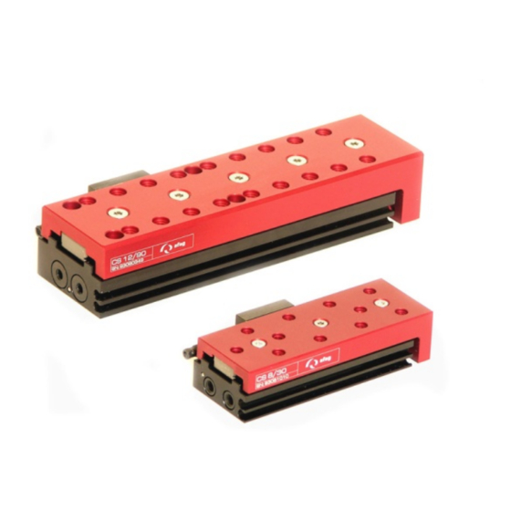
3.1.3 Description of the module CS 12 CS 8 Base body Stop screw with integrated shock absorber Slide Sensor nuts Air connection The CS 8/12 consists of the base body (1) with pneumatic connections and cylinder and the moveably mounted slide (2). The stop positions are set by means of a stop screw with integrated shock absorber (3). -
Page 19: Scope Of Supply
Modifications on the module that are not described in these Montage Instructions or have not been approved in writing by Afag are not permitted. In case of improper changes or assembly, installation, operation, maintenance or repairs, Afag rejects all liability. -
Page 20: Warranty
• Wear parts (e.g. shock absorbers) are not covered by the warranty. * The warranty covers the replacement or repair of defective Afag parts. No further claims will be accepted. The warranty will be voided in event of the following: •... -
Page 21: Dimension Drawing Cs 8
3.1.8 Dimension drawing CS 8 CS8-CS12-OI-vers. 4.2 gb. 20190312... -
Page 22: Technical Data Cs 8
3.1.9 Technical data CS 8 CS8-CS12-OI-vers. 4.2 gb. 20190312... -
Page 23: Dimension Drawing Cs 12
3.2.0 Dimension drawing CS 12 CS8-CS12-OI-vers. 4.2 gb. 20190312... -
Page 24: Technical Data Cs 12
3.2.1 Technical data CS 12 CS8-CS12-OI-vers. 4.2 gb. 20190312... -
Page 25: Pneumatic Connection
3.2.2 Pneumatic connection The shock absorber is located at the side of the base body of the CS 8/30 / CS 8/60 /CS 12/30 / CS 12/60 / CS 12/90 Two pneumatic connections (M5), are on the rear.. The CS 8/10 only has 2 air connections on the rear. Pneumatic connections that are not used must be closed airtight with the locking screws included in the scope of supply. -
Page 26: Preparation For Start-Up
3.2.3 Preparation for start-up If they put before the introduction only shock absorber, so that slide is absorbed in position. Sensor nuts Air connection M5 Shock absorber Shock absorber Air connection Air connection M5 CAUTION The CS module must not be operated without shock absorbers installed as it may be damaged due to missing damping (CS modules up to 10 mm stroke, may also be operated with stop screws). -
Page 27: Notes On Elastomer Shock Absorbers
3.2.4 Notes on elastomer shock absorbers NOTE Elastomer shock absorbers are actually a spring element, i.e. the holding force of the carriage is more or less reduced in the end position as compared with hydraulic dampers and depending on the setting of the absorber stroke. -
Page 28: Installation Of The Sensors
3.2.5 Installation of the sensors Clamping proximity switches are used to query the CS stop positions. Polling of the stop positions is monitored by an LED on the initiator. If the LED switch status does not change during inquiry of the stop positions the sensor is faulty and must be replaced. -
Page 29: Fitting The Proximity Switch In The Module Grooves
3.2.7 Fitting the proximity switch in the module grooves There are two C-grooves for the proximity switches on the right-hand side of the CS module. These proximity switches are used to query the stop positions. Proximity switch Screw for fastening the clamping piece in the groove Screw for fastening the proximity Clamping piece... -
Page 30: Start-Up Of The Cs Compact Slide
3.2.8 Start-up of the CS compact slide Aerate the total system slowly. Pay attention to the permissible values (technical data) regarding: load capacity motion frequency moment loads on the guide system CAUTION Limbs may be squeezed by moving components. Make sure that there are no persons or tools within the operating range of the ... -
Page 31: Maintenance Instructions
4.0.0 Maintenance Instructions The shock absorbers and stop screws must undergo regular functionality checks, and be replaced if required. We recommend replacing the shock absorber after a maximum of 5 million load cycles. If shock absorbers are missing, defective or incorrectly set up, the functionality of the module will be compromised and may lead to its destruction! 4.1.0 Maintenance and servicing CAUTION... -
Page 32: Servicing
Open guides and piston rods should be covered with a grease layer to avoid formation of rust. Standard greasing Afag: - Staburax NBU8EP (flat guides) - Blasolube 301 (piston rods) CS8-CS12-OI-vers. 4.2 gb. 20190312... -
Page 33: Fault During Operation
4.1.2 Fault during operation Fault Mögliche Ursache Abhilfe The CS-Compact slide The stop / shock Re-adjust the stop / shock slides hard into the end absorbers are not absorbers positions adjusted correctly. Reposition again hard in Shock absorbers are Replace the shock absorber the end positions demaged (See... -
Page 34: Adjustment Of The Elastomer Shock Absorber
4.1.4 Adjustment of the elastomer shock absorber The power values indicated in the technical data are applicable to a maximum set stroke (H max) when the adjusting pin was completely turned in. The defined fixed end position can however be reached when the stroke is reduced correspondingly resulting in less power and thus a reduced drive force (F a). -
Page 35: Disassembly And Repair
4.1.5 Disassembly and repair When the module is damaged it can be returned to Afag Automation AG for repair. CAUTION The module may only be disassembled when the system is aerated and deactivated. If pneumatic connections are disconnected when they are under pressure, this may result in serious personal injury due to fast movements of moving parts. -
Page 36: Accessories / Spare Parts
4.1.6 Accessories / Spare parts Item Order No. Centering bushings 5x2.5 (2 Stk.) 50035831 (CS 8) Centering bushings 7x3 (2 Stk.) 11016850 (CS 12) Sensor INI c10x28.5-Em-PNP-close-M8x1 50033432 (CS 8 + CS 12) Sensor INI d3x22-Sn0.8-PNP-close-M8x1 50001023 (CS 8) Alternative Elastomer shock absorber ASED M5x0.5-1 50282683 (CS 8) -
Page 37: Disposal
5.0.0 Disposal NOTE CS modules which cannot be used any more must not be disposed off as a complete unit, but must be disassembled and recycled according to the type of material. Materials than cannot be recycled must be disposed off in accordance with the legal regulations. - Page 38 CS8-CS12-OI-vers. 4.2 gb. 20190312...
- Page 39 CS8-CS12-OI-vers. 4.2 gb. 20190312...
- Page 40 Afag Automation AG Fiechtenstrasse 32 CH - 4950 Huttwil Switzerland Tel.: +41 62 959 87 02 Fax.: +41 62 959 87 87 sales@afag.com www.afag.com...
Need help?
Do you have a question about the Compact Slide CS 8 and is the answer not in the manual?
Questions and answers