Table of Contents
Advertisement
Quick Links
Assembly and operating instructions
Rotary-gripper module
(pneumatic/electric)
Translation of the Original Assembly Instructions EN
GMQ 12/K/RE-50
◼
GMQ 12/P/RE-50
◼
GMQ 12/P-01/RE-50
◼
GMQ 12/K/RE-50 (18-100V)
◼
GMQ 12/P/RE-50
◼
GMQ 12/P-01/RE-50 (18-100V)
◼
Assembly instructions EN
GMQ 12 / RE-50
Order no.:
Order no.:
Order no.:
Order no.:
Order no.:
Order no.:
◼
◼
GMQ 12/RE-50
14.06.2023
50394843
50394844
50394846
50395566
50395567
50395569
◼
V3.5
1–49
Advertisement
Table of Contents

Subscribe to Our Youtube Channel
Related Manuals for Afag GMQ 12 / RE-50 Series


Summary of Contents for Afag GMQ 12 / RE-50 Series
- Page 1 Assembly and operating instructions Rotary-gripper module (pneumatic/electric) GMQ 12 / RE-50 Translation of the Original Assembly Instructions EN 50394843 GMQ 12/K/RE-50 Order no.: ◼ 50394844 GMQ 12/P/RE-50 Order no.: ◼ 50394846 GMQ 12/P-01/RE-50 Order no.: ◼ 50395566 GMQ 12/K/RE-50 (18-100V) Order no.:...
- Page 2 Your Afag team © Subject to modifications The rotary modules have been designed by Afag Automation AG according to the state of the art. Due to the constant technical development and improvement of our products, we reserve the right to make technical changes at any time.
-
Page 3: Table Of Contents
Table of contents Table of contents General ........................5 Contents and purpose of these assembly instructions ......... 5 Explanation of symbols................. 5 Additional symbols ..................6 Applicable documents .................. 7 Warranty ....................... 7 Liability ......................7 Safety instructions ....................8 General ...................... - Page 4 Table of contents Storage ....................... 23 Design and description ..................24 Design rotary-gripper module GMQ 12/RE-50 ........... 24 Product description ..................25 Accessories ....................26 Installation, assembly and setting ..............27 Safety instructions ..................27 Assembly & attachment ................28 6.2.1 Fastening the module ................
-
Page 5: General
General General 1.1 Contents and purpose of these assembly instructions These assembly instructions contain important information on assembly, commissioning, functioning and maintenance of the rotary-gripper module GMQ 12/RE-50 to ensure safe and efficient handling and operation. Consistent compliance with these assembly instructions will ensure: ▪... -
Page 6: Additional Symbols
General Further warning signs: Where applicable, the following standardised symbols are used in this manual to point out the various potential health risks. Warning - Dangerous electrical voltage. Warning - Risk of injury from contact with hot surfaces. Warning - Risk of hand and finger injury due to uncontrolled movements of components. -
Page 7: Applicable Documents
This does also apply to defective accessories and wear parts. Normal wear and tear are excluded from the warranty. The warranty covers the replacement or repair of defective Afag parts. Further claims are excluded. The warranty shall expire in the following cases: ▪... -
Page 8: Safety Instructions
Safety instructions Safety instructions 2.1 General This chapter provides an overview of all important safety aspects to ensure safe and proper use of the gripper and optimal protection of personnel. Failure to follow the directions and safety instructions given in this instructions manual may result in serious hazards. -
Page 9: Obligations Of The Operator And The Personnel
▪ the operating company shall be solely responsible for such damage, and ▪ AFAG does not assume any liability for damage caused by improper use. 2.4 Obligations of the operator and the personnel 2.4.1... -
Page 10: Personnel Requirements
Safety instructions 2.5 Personnel requirements 2.5.1 Personnel qualification The activities described in the assembly instructions require specific requisites at the level of professional qualifications of the personnel. Personnel not having the required qualification will not be able to asses the risks that may arise from the use of the module thus exposing himself and others to the risk of serious injury. -
Page 11: Changes And Modifications
2.7 Changes and modifications No changes may be made to the module which have not been described in these assembly instructions or approved in writing by Afag Automation AG. Afag Automation AG accepts no liability for unauthorised changes or improper assembly, installation, commissioning, maintenance or repair work. -
Page 12: Danger Due To Electricity
Safety instructions Always keep the assembly instructions ready at hand at the workplace! Please, also observe: ▪ the general and local regulations on accident prevention and environmental protection, ▪ the safety information sheet for the module. WARNING Danger - Do not use in unsuitable environment ! The modules are designed for use in non explosive atmospheres. -
Page 13: Danger Due To High Temperatures
Safety instructions 2.8.3 Danger due to high temperatures CAUTION Danger of injury from hot surfaces. During continuous operation of the modules, the surface of the module heats ▪ Before touching hot surfaces without protective gloves, make sure they have cooled down to ambient temperature. 2.8.4 Mechanical hazards CAUTION... -
Page 14: Technical Data
Technical data Technical data 3.1 Rotary-gripper module GMQ 12 3.1.1 Dimensional drawing GMQ 12 Fig. 1 Dimensional drawing module GMQ 12 14 – 49 ◼ ◼ ◼ Assembly instructions EN GMQ 12/RE-50 14.06.2023 V3.5... -
Page 15: Technical Data Gmq 12
Technical data 3.1.2 Technical data GMQ 12 ◼ ◼ ◼ Assembly instructions EN GMQ 12/RE-50 14.06.2023 V3.5 15–49... -
Page 16: Preferred Combinations
Technical data 3.1.3 Preferred combinations 16 – 49 ◼ ◼ ◼ Assembly instructions EN GMQ 12/RE-50 14.06.2023 V3.5... -
Page 17: Diagrams Gripping Force Gmq 12
Technical data 3.1.4 Diagrams gripping force GMQ 12 ◼ ◼ ◼ Assembly instructions EN GMQ 12/RE-50 14.06.2023 V3.5 17–49... -
Page 18: Rotary Module Re-50 (Without Flange)
Technical data 3.2 Rotary module RE-50 (without flange) 3.2.1 Dimensional drawing RE-50 Fig. 2 Dimensional drawing of rotary module RE-50 18 – 49 ◼ ◼ ◼ Assembly instructions EN GMQ 12/RE-50 14.06.2023 V3.5... -
Page 19: Technical Data Re-50
Technical data 3.2.2 Technical data RE-50 ◼ ◼ ◼ Assembly instructions EN GMQ 12/RE-50 14.06.2023 V3.5 19–49... -
Page 20: Preferred Combinations
Technical data 3.2.3 Preferred combinations 20 – 49 ◼ ◼ ◼ Assembly instructions EN GMQ 12/RE-50 14.06.2023 V3.5... -
Page 21: Load Diagrams Re-50 (Without Flange)
Technical data 3.2.4 Load diagrams RE-50 (without flange) ◼ ◼ ◼ Assembly instructions EN GMQ 12/RE-50 14.06.2023 V3.5 21–49... -
Page 22: Transport, Packaging And Storage
Transport, packaging and storage Transport, packaging and storage 4.1 Safety instructions CAUTION Risk of injury when unpacking the module! The rotary-gripper modules are packed in the original packaging (cardboard box). If handled incorrectly, the module may fall out of cardboard box when unpacked and cause limb injuries. -
Page 23: Transport
▪ Relative air humidity: < 90%, non condensing 4.4 Packaging The module is transported in the Afag Automation AG transport packaging. If no Afag packaging is used, the module must be packed in such a way that it is protected against shocks and dust. NOTICE... -
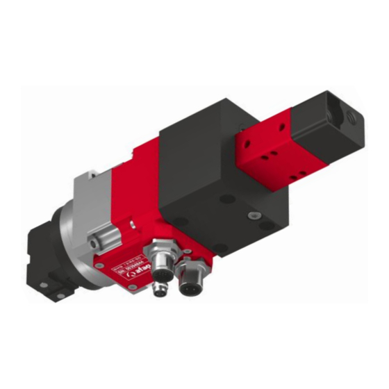
Page 24: Design And Description
Design and description Design and description 5.1 Design rotary-gripper module GMQ 12/RE-50 24 – 49 ◼ ◼ ◼ Assembly instructions EN GMQ 12/RE-50 14.06.2023 V3.5... -
Page 25: Product Description
The rotary modules are equipped with a 17-pin industrial connector (G13) and a 4-pin M15 connector. The rotary modules are designed for operation with the Afag controllers SE-Power 1kVA, SE-48 and SE-24. The modules can also be operated with other third-party controllers. -
Page 26: Accessories
Design and description 5.3 Accessories Designation Order Number Centring sleeve 7x3mm 11016850 Centring sleeves 9x4mm 11004942 Flange plate set RE-50 50294008 Flange plate set RE-50 50294009 Motor cable-M12-5m-0-open (SE-Power) 50290459 Motor cable-M12-10m-0-open (SE-Power) 50310506 Motor cable-M12-5m-90-open (SE-Power) 50290460 Motor cable-M12-10m-90-open (SE-Power) 50310507 Motor cable-M15-3m-0-0 (SE24/48) 50332418... -
Page 27: Installation, Assembly And Setting
Installation, assembly and setting Installation, assembly and setting The rotary-gripper module is an incomplete machine. For safe operation, the module must be integrated into the safety concept of the system in which it is installed. During normal operation, it must be ensured that the user cannot interfere with the working area of the module. -
Page 28: Assembly & Attachment
Installation, assembly and setting 6.2 Assembly & attachment The rotary-gripper module can be mounted both in horizontal and vertical position. 6.2.1 Fastening the module The fastening is performed to the black intermediate part in a 30x30 mm grid by means of 4 x M4 screws. Fastening thread 2xM3 (e.g. - Page 29 Installation, assembly and setting ◼ ◼ ◼ Assembly instructions EN GMQ 12/RE-50 14.06.2023 V3.5 29–49...
-
Page 30: Electrical Interfaces
Installation, assembly and setting 6.2.3 Electrical interfaces Motor cable (M12 or M15) brown white 3 PE blue black Encoder cable (G10 or G12) + 5 V n.a. n.a. n.a. Sensor plug (M5x0.5) 30 – 49 ◼ ◼ ◼ Assembly instructions EN GMQ 12/RE-50 14.06.2023 V3.5... -
Page 31: Gripping Jaws
Installation, assembly and setting 6.3 Gripping jaws If the GMQ 12/RE-50 module was ordered without tongs, the tongs can be reordered. The GMQ 12 gripper drive can be equipped with the normal gripping jaws of the GMQ 12 pneumatic gripper. There are 4 types to choose. 18-100 V 1. -
Page 32: Dismounting The Gripping Jaws
Installation, assembly and setting 6.3.2 Dismounting the gripping jaws The drawbar on the gripping drive must be extended to mount the gripping jaws! Required tools: GMQ 12/K Socket wrench key width 5.5 GMQ 12/P Socket wrench key width 5.5 GMQ 12/P-01 Allan key size 2.5 To dismount of the gripping jaws, proceed as follows: 1. -
Page 33: Manufacture Of The Gripper Fingers
The gripping fingers are not included in the scope of delivery. The preparation of the gripping fingers is the responsibility of the system operator. The jaws of the grippers are provided with a standard fit (12 H7). The drawings of the gripping jaws can be found in the AFAG technical catalogue! ◼... -
Page 34: Commissioning
Commissioning Commissioning After connection, the GMQ-modules are put into operation for the first time via the system controller. Commissioning must only be carried out in setup/jog mode. 7.1 Safety instructions DANGER Risk of injury due to electric shock! Unauthorized removal of the plug cover causes a risk of electric shock! ▪... -
Page 35: Preparatory Activities For Commissioning
Please also observe the installation instructions for the control unit used! 7.2 Preparatory activities for commissioning The rotary module is designed for operation with AFAG - servo controller. The modules can also be operated with other control systems. The operation of the AFAG servo controller is described in the separate installation instructions for the respective servo controller. -
Page 36: Setting-Up And Retrofitting
Commissioning 7.4 Setting-up and retrofitting Adjusting the cable connection position The position of the cable connections is freely selectable. In the standard delivery of the module, the cable connections point to the front. If necessary, the black mounting part of the module can be rotated so that the cable connection on the module is on the left or right side. - Page 37 Commissioning Procedure: Change the position of the cable connections 1. Loosen four screws on the RE-50 module with the 2.5 mm hexagonal screwdriver. 2. Remove the module RE-50, then turn it to the desired side and mount it again. 3. Screw the RE-50 module back into the new position. The process is complete.
-
Page 38: Fault Elimination
Fault elimination Fault elimination 8.1 Safety instructions DANGER Risk of injury due to electric shock! Unauthorized removal of the plug cover causes a risk of electric shock! ▪ Do NOT dismount the plug cover! ▪ Avoid any action on the module which could endanger safety! WARNING Danger of injury due to faulty troubleshooting! Poorly performed troubleshooting work can lead to serious injuries and... -
Page 39: Fault Causes And Remedy
▪ Check end position sensor cable the end position sensor ▪ End position sensor defective ▪ Replace end position sensor (only by Afag service technician - see below!) ▪ Incorrect homing (reference) ▪ Check the reference travel direction, Rotating shaft (gripping jaws) -
Page 40: Maintenance And Repair
Maintenance and Repair Maintenance and Repair 9.1 General notes The rotary-gripper modules are almost maintenance-free. Nevertheless, some maintenance work must be carried out to ensure an optimum operating condition of the modules. 9.2 Safety instructions DANGER Risk of injury due to electric shock! Unauthorized removal of the plug cover causes a risk of electric shock! ▪... -
Page 41: Maintenance Activities And Maintenance Intervals
Maintenance and Repair 9.3 Maintenance activities and maintenance intervals ▪ The maintenance intervals must be strictly observed. The intervals refer to a normal operating environment. 9.3.1 Overview of the maintenance points Fig. 7 Maintenance points of the module System Maintenance Interval Maintenance work Remarks... -
Page 42: Repair And Overhaul
Maintenance and Repair 9.4 Repair and overhaul 9.4.1 Replacing the GMQ 12 gripper drive If a gripper drive fails or is defective after the warranty period, it can be replaced by the system operator as described below. A special tool (assembly spanner combination) is required to replace the gripper drive and must be ordered separately! Product Order Number... - Page 43 Maintenance and Repair 3. Insert the assembly key. 4. Use the assembly key to loosen the pivot bearing so that the pivot bearing can be removed together with the drawbar. 5. Loosen the clamping screw on the middle section. 6. Remove the gripper drive. The disassembly of the gripper drive is completed.
-
Page 44: Replacing The Re-50 Rotary Module
Maintenance and Repair 9.4.2 Replacing the RE-50 rotary module If a gripper drive fails or is defective after the warranty period, it can be replaced by the system operator as described below. Product Order Number RE-50 50294005 RE-50 (18-100V) 50328767 If the rotary module is replaced by the system operator within the warranty period, the warranty claim expires. -
Page 45: Replace End Position Sensor
Maintenance and Repair 3. Mount the new RE-50 module on the diagonal centring sleeves on the intermediate part of the module. Note the cable connections on the new rotary module! The RE-50 module has been replaced. 9.4.3 Replace end position sensor The end position sensor may only be replaced by the manufacturer. -
Page 46: Spare Parts And Repair Work
Maintenance and Repair 9.5 Spare parts and repair work Afag Automation AG offers a reliable repair service. Defective modules can be sent to AFAG for warranty repair within the warranty period. Damaged rotary-gripper modules may only be replaced or repaired by Afag... -
Page 47: Decommissioning, Disassembly, Disposal
Decommissioning, disassembly, disposal 10 Decommissioning, disassembly, disposal The rotary-gripper modules must be properly dismantled after use and disposed of in an environmentally friendly manner. 10.1 Safety instructions WARNING Danger of injury due to improperly performed activities! Improperly carried out activities can result in considerable material damage and serious injury. -
Page 48: Declaration Of Incorporation
The relevant technical documentation was created according to Annex VII, Part B of the above-mentioned Directive . Authorised representative for compiling the technical documentation: Niklaus Röthlisberger, Product Manager, Afag Automation AG, CH-6144 Zell Zell, 31.05.2023 Adrian Fuchser Klaus Bott... - Page 49 Afag Automation Americas Afag Automation APAC Schaeff Machinery & Services LLC. Afag Automation Technology (Shanghai) Co., Ltd. 883 Seven Oaks Blvd, Suite 800 Room 102, 1/F, Bldg. 56, City Of Elite Smyrna, TN 37167 No.1000, Jinhai Road, Pudong New District...
Need help?
Do you have a question about the GMQ 12 / RE-50 Series and is the answer not in the manual?
Questions and answers