Table of Contents

Related Manuals for Afag LE-50 Series


Summary of Contents for Afag LE-50 Series
- Page 1 Linear modules electrical LE-50 I LE-60 I LE-70 Declaration of Incorporation Module Information Montage Instructions Maintenance Instructions “Translation” of the Original Montage Instructions © Copyright by Afag Automation AG...
- Page 2 These Montage Instructions apply to: Type Order No. Type Order No. LE-50-XXX 50407225 LE-50-D-XXX 50407228 LE-60-XXX 50407226 LE-60-D-XXX 50407229 LE-70-XXX 50407227 LE-70-D-XXX 50407230 Assembly and initial start-up must be carried out by qualified personnel only and ac- cording to these Montage Instructions. Version of this docu- LE-50-LE-60-LE-70-OI-vers.
-
Page 3: Table Of Contents
Contents 1.0.0 EC Declaration for Incorporation ............2.0.0 Module Information ................. 2.1.0 Safety ......................7 2.1.1 Transport, Handling, Storage ................. 7 2.1.2 Module Description ..................8 Description of the module types ..............10 2.1.3 Installation, Connection ................11 2.1.4 Installation and mounting options ..............12 Tightening moments for bolts ............... - Page 4 3.1.5 Commissioning, Operation, Training ..............33 3.1.6 Preparation for commissioning ................. 34 3.1.7 Commissioning ....................35 3.1.8 Set conversion ....................36 3.1.9 Normal operation ....................37 4.0.0 Maintenance Instructions ..............4.1.0 Maintenance ....................38 4.1.1 Regular maintenance..................39 4.1.2 Lubrication of the linear module slide ............. 40 Additional maintenance ..................
-
Page 5: Ec Declaration For Incorporation
1.1.0 According to 2006/42/EC dated 09. June 2006, Appendix II B VI for Incorporation of partly completed machinery. The manufacturer: Afag Automation AG, Fiechtenstrasse 32, CH-4950 Huttwil Tel. 0041 (0)62 959 87 02, www.afag.com As manufacturer of the partly completed machine we declare that:... - Page 6 Name and address of the person authorised to compile the relevant technical documentation: Lanz Beat, PM & Marketing-Services, Afag Automation AG Place/Date: Huttwil, 28.07.2014 Markus Werro Siegfried Egli Managing Director Head of HT Afag Automation AG Afag Automation AG LE-50-LE-60-LE-70-OI-vers. 2.1 gb. 28.07.14...
-
Page 7: Module Information
Modifications to the linear modules LE that are not described in this Montage Instruc- tion or have not been approved in writing by the company Afag Automation AG are not permitted. In case of improper changes or assembly, installation, operation, maintenance or repairs, Afag Automation AG rejects all liability. -
Page 8: Module Description
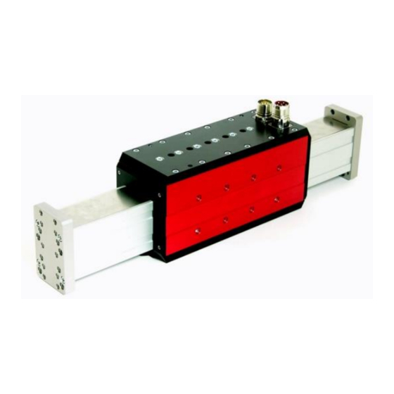
(linear motor). They are exclusively suitable for the horizontal movement of module superstructures and loads. The LE linear modules are designed for being operated with the Afag SE-Power con- trol system. They can also be operated with other controller types. - Page 9 1. Basic unit 7. Measuring head 2. Cantilever arm 8. Measuring tape 3. Primary part 9. End plate 4. Secondary part 10. Lubrication nipple 5. Aluminium profile 11. Limit stop 6. Linear guide 12. Motor/encoder con- nector LE-50-LE-60-LE-70-OI-vers. 2.1 gb. 28.07.14...
-
Page 10: Description Of The Module Types
The LE linear module consists of the basic unit (1) and the cantilever arm (2). The primary part (7) of the linear motor, the measuring head (5) and the motor or encoder connector (11) are integrated in the slide. The cantilever arm (2) consists of an alu- minium profile (2) with the mounted-on linear guide (6), secondary parts (8) and measuring tape (4). -
Page 11: Installation, Connection
2.1.3 Installation, Connection WARNING The LE linear modules are moved by the electric control. If the linear modules cannot move freely there is danger of injuries and bruises near the add-ons. If add-ons at the LE linear modules could cause danger in con- nection with the moving slide or superstructures a safe opera- tion must be ensured. -
Page 12: Installation And Mounting Options
2.1.4 Installation and mounting options The LE linear modules are designed for cantilever operation. They can however also be used as gantry version. Cantilever operation Gantry application Movable cantilever Firmly mounted cantilever Firmly mounted slide Movable slide Useful load on the cantilever arm Useful load on the slide NOTE Please note:... -
Page 13: Tightening Moments For Bolts
The mounting grids and the mounting threads are shown on the dimensional draw- ings in chapter 3.5, page 19 of these Montage Instructions. (Further accessories can be found in the technical catalogue or on the website www.afag.com Use the centering bushings included in the scope of supply to determine the position and insert these bushings in the opposite borings of the mounting grid. -
Page 14: Installation Into A System
2.1.5 Installation into a system The series of the LE linear modules is used for the linear, smooth movement of rigid- ly mounted loads under the ambient and Installation conditions defined for this mod- ule, see Technical data in chapter 3.5 of these Installation Instructions. DANGER The LE linear modules must not be used in an explosion- hazardous environment. - Page 15 CAUTION The LE linear module is a partly complete machine. The LE linear modules must be integrated in the safety concept of the system so that a safe operation can be ensured. Ensure that the operating personnel cannot reach into the op- erating range of the LE linear modules during operation.
-
Page 16: Preferred Combinations To Le-50
2.1.6 Preferred combinations to LE-50 LE-50-LE-60-LE-70-OI-vers. 2.1 gb. 28.07.14... -
Page 17: Preferred Combinations To Le-60
2.1.7 Preferred combinations to LE-60 LE-50-LE-60-LE-70-OI-vers. 2.1 gb. 28.07.14... -
Page 18: Preferred Combinations To Le-70
2.1.8 Preferred combinations to LE-70 LE-50-LE-60-LE-70-OI-vers. 2.1 gb. 28.07.14... -
Page 19: Electrical Interfaces (Pin Assignment)
2.1.9 Electrical interfaces (pin assignment) Motor Encoder Motor connector pinout: Signal Motor winding 1 (U) Motor winding 2 (V) Motor winding 3 (W) GND Motor (PE) Temperature sensor PTC Temperature sensor PTC Encoder connector pinout Signal + 5V DC, Encoder GND Encoder Canal A Canal A/... -
Page 20: Le Linear Programming Modules
The programming depends on the control system used. Observe the respective manuals of the control system supplier. If the Afag SE-Power control system is used, please observe the Montage Instruc- tions which are supplied together with the control system. You can also download this Montage Instructions from the Afag website: www.afag.com... -
Page 21: Montage Instructions
Directive 206/42/EG, where appropriate. Name and address of the person authorised to compile the relevant technical docu- mentation: Lanz Beat, PM & Marketing-Services, Afag Automation AG LE-50-LE-60-LE-70-OI-vers. 2.1 gb. 28.07.14... -
Page 22: The Delivery
3.1.1 The delivery Number Description Module Centering bushings Ø 7x3 mm Centering bushings Ø 8x3.5 mm 2 Centering bushings Ø 9 x 4.0 mm 1 Montage Instructions Table 2: Delivery 3.1.2 Intended use The LE linear modules are used for the smooth rotary movement of loads in non- explosion hazardous ambient and Installation conditions that are specified for this module (see Technical Data in chapter 3.5). -
Page 23: Warranty
Modifications on the module that are not described in this Montage In- structions or have not been approved in writing by Afag are not permitted. In case of improper changes or assembly, installation, operation, maintenance or repairs, Afag AG rejects all liability. -
Page 24: Dimensional Drawing Le-50
3.1.5 Dimensional drawing LE-50 Figure 2: Dimension drawing LE-50 LE-50-LE-60-LE-70-OI-vers. 2.1 gb. 28.07.14... -
Page 25: Technical Data Le-50
3.1.6 Technical data LE-50 LE-50-LE-60-LE-70-OI-vers. 2.1 gb. 28.07.14... -
Page 26: Dimensional Drawing Le-60
3.1.7 Dimensional drawing LE-60 LE-50-LE-60-LE-70-OI-vers. 2.1 gb. 28.07.14... -
Page 27: Technical Data Le-60
3.1.8 Technical data LE-60 LE-50-LE-60-LE-70-OI-vers. 2.1 gb. 28.07.14... -
Page 28: Dimensional Drawing Le-70
3.1.9 Dimensional drawing LE-70 LE-50-LE-60-LE-70-OI-vers. 2.1 gb. 28.07.14... -
Page 29: Technical Data Le-70
3.2.0 Technical data LE-70 LE-50-LE-60-LE-70-OI-vers. 2.1 gb. 28.07.14... -
Page 30: Slide Unit Load Factors Le-50
3.2.1 Slide unit load factors LE-50 LE-50-LE-60-LE-70-OI-vers. 2.1 gb. 28.07.14... -
Page 31: Slide Unit Load Factors Le-60
3.1.2 Slide unit load factors LE-60 LE-50-LE-60-LE-70-OI-vers. 2.1 gb. 28.07.14... -
Page 32: Slide Unit Load Factors Le-70
3.1.3 Slide unit load factors LE-70 Figure 3 Slide unit load factors LE-50-LE-60-LE-70-OI-vers. 2.1 gb. 28.07.14... -
Page 33: Noise Emissions
3.1.4 Noise emissions NOTE The LE linear module generates 72 dB(A) in full-load operation. De- pending on the add-ons, the environment and the resonance of the protective device these values may be exceeded and result in a dis- turbing higher noise level. CAUTION It is the responsibility of the system manufacturer to ensure that the permitted noise limit values are complied with. -
Page 34: Preparation For Commissioning
Observe the Montage Instructions of the control system used. 3.1.6 Preparation for commissioning The LE linear module is designed for being operated with the Afag SE-Power control system. It can also be operated with other controller types. Operation of the SE-Power control system is described in the separate operating in- structions. -
Page 35: Commissioning
3.1.7 Commissioning CAUTION The commissioning of the axle system should be set-up or Step operation done. Incorrect programming can uncontrolled movement of the axle system trigger. Fast or unintentional movements of the system can cause injury or death, property damage, and you cause. Ensure that off when working on the control axle system and is switched on again. -
Page 36: Set Conversion
WARNING It is the responsibility of the system manufacturer that persons perform their work properly when adjusting the LE linear mod- ule in an open system so that an uncontrolled start-up of the axis is prevented. 3.1.8 Set conversion WARNING The LE linear modules are moved by the electric control. -
Page 37: Normal Operation
3.1.9 Normal operation WARNING The LE linear modules are moved by the electric control. If the LE linear module cannot move freely there is danger of injuries and bruises near the add-ons. If add-ons at the LE linear module could cause danger in con- nection with the moving slide a safe operation must be ensured. -
Page 38: Maintenance Instructions
4.0.0 Maintenance Instructions 4.1.0 Maintenance DANGER The strong magnetic fields of the LE may interfere with and im- pair the function of electronic devices, such as pacemakers, even when the module is switched off. Persons with a pacemaker must keep a safety distance of at least 50 cm. -
Page 39: Regular Maintenance
4.1.1 Regular maintenance DANGER The strong magnetic fields of the LE may interfere with and im- pair the function of electronic devices, such as pacemakers, even when the module is switched off. Strong magnetic fields Persons with a pacemaker must keep a safety distance of at least 50 cm. -
Page 40: Lubrication Of The Linear Module Slide
WARNING Lubricants with additives such as MoS , graphite or PTFE may not be used to service the linear guide. Lubrication of the linear module slide Schmiernippel LE-Modul Grease nipples an the side guide (In the D version) Table 4 Lubrication of the linear module slide Additional maintenance Under the ambient conditions mentioned below the LE linear module does not re- quire any further maintenance:... - Page 41 Control of the safety labels DANGER The strong magnetic fields of the LE may interfere with and im- pair the function of electronic devices, such as pacemakers, even when the module is switched off. Strong magnetic fields Persons with a pacemaker must keep a safety distance of at least 50 cm.
- Page 42 With the LE modules can be implemented cross structures which are completely dif- ferent Operation to the user. For detailed questions please contact our Technicians, they are willing for your application to offer the best solution. www.afag.com Caution Here, the fingers can be pinched...
- Page 43 Caution Here, the fingers can be pinched LE-50-LE-60-LE-70-OI-vers. 2.1 gb. 28.07.14...
- Page 44 Caution Here, the fingers can be pinched LE-50-LE-60-LE-70-OI-vers. 2.1 gb. 28.07.14...
-
Page 45: Troubleshooting And Repair
CAUTION By moving the slide can be both in the loose, bind, as in the functional state of finger! 4.1.3 Troubleshooting and repair WARNING The LE linear modules are moved by the electric control. If the LE linear modules cannot move freely there is danger of injuries and bruises near the add-ons. -
Page 46: Trouble When Carrying Out The Reference Run
Linear drive wrongly con- Check pin assignment and not move nected correct, if necessary Carry out functional check Motor connection inter- Check motor cable rupted Linear drive defective Have the linear drive re- placed by Afag AG LE-50-LE-60-LE-70-OI-vers. 2.1 gb. 28.07.14... - Page 47 Increased running noise in Linear guide insufficiently Lubricate linear guide the linear guide lubricated Appreciable play in the Have the linear guide re- linear guide placed by Afag AG Table 4: Disturbance, Possible Cause, Remedy LE-50-LE-60-LE-70-OI-vers. 2.1 gb. 28.07.14...
-
Page 48: Accessories
On request Table 5: Accessories 4.1.6 Exchange and repair When the module is damaged it can be returned to Afag Automation AG for repair. CAUTION Switch off and secure the control system before the LE linear module is removed out of the system. -
Page 49: Disposal
Disposal NOTE LE linear modules which cannot be used any more must not be dis- posed of as a complete unit, but must be disassembled and recycled according to the type of material. Materials than cannot be recycled must be disposed of in accordance with the legal regulations. Annex 4.1 List of figures Figure 1: Pin Assignment.................. - Page 50 LE-50-LE-60-LE-70-OI-vers. 2.1 gb. 28.07.14...
- Page 51 LE-50-LE-60-LE-70-OI-vers. 2.1 gb. 28.07.14...
- Page 52 Afag Automation AG Fiechtenstrasse 32 4950 Huttwil Switzerland Tel.: +41 (0)62 959 87 02 Fax.: +41 (0)62 959 87 87 Tel.: +41 (0)62 – 959 86 86 sales@afag.com Fax.: +41 (0)62 – 959 87 87 www.afag.com e-mail: sales@afag.com Internet: www.afag.com...
Need help?
Do you have a question about the LE-50 Series and is the answer not in the manual?
Questions and answers