Table of Contents
Advertisement
Quick Links
Assembly and operating instructions
Translation of the Original Assembly Instructions EN
LM 12/30
Order No.: 11010377
LM 12/60
Order No.: 11010378
LM 12/90
Order No.: 11010379
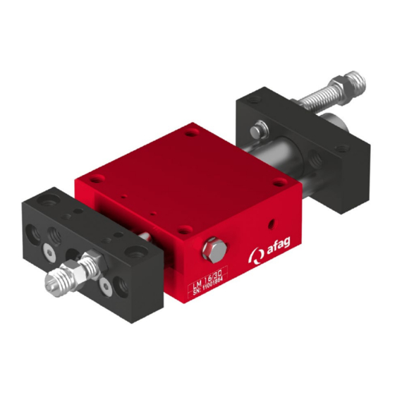
LM 16/30
Order No.: 11001864
LM 16/60
Order No.: 11001865
LM 16/90
Order No.: 11001866
Assembly Instructions EN
Linear Modules
LM 12
LM 12 I LM 16
Edition 11/2020
I
LM 16
Rev. 2.5
1–52
Advertisement
Chapters
Table of Contents

Related Manuals for Afag LM 12/30


Summary of Contents for Afag LM 12/30
- Page 1 Assembly and operating instructions Linear Modules LM 12 LM 16 Translation of the Original Assembly Instructions EN LM 12/30 Order No.: 11010377 LM 12/60 Order No.: 11010378 LM 12/90 Order No.: 11010379 LM 16/30 Order No.: 11001864...
- Page 2 Your Afag team © Subject to modifications The linear modules have been designed by Afag Automation AG according to the state of the art. Due to the constant technical development and improvement of our products, we reserve the right to make technical changes at any time.
-
Page 3: Table Of Contents
Table of contents Table of contents General ........................6 Contents and purpose of these assembly instructions ......... 6 Explanation of symbols................. 6 Additional symbols ..................7 Applicable documents .................. 8 Warranty ....................... 8 Liability ......................8 Safety instructions ....................9 General ...................... - Page 4 Table of contents Packaging ....................25 Storage ....................... 26 Structure and description ................... 27 Design of linear module ................27 Product description ..................27 Accessories ....................28 5.3.1 Accessories LM 12 ................28 5.3.2 Accessories LM 16 ................28 Installation, assembly & setting ................. 29 Safety Instructions for installation &...
- Page 5 Table of contents 10.3 Disposal ...................... 47 Declaration of incorporation ................48 Assembly Instructions EN LM 12 I LM 16 Edition 11/2020 Rev. 2.5 5–52 ...
-
Page 6: General
General General 1.1 Contents and purpose of these assembly instructions These assembly instructions contain important information on assembly, commissioning, functioning and maintenance of the linear module to ensure safe and efficient handling of the linear module LM 12 and LM 16. Consistent compliance with these assembly instructions will ensure: ... -
Page 7: Additional Symbols
General This note contains important additional information as well as useful tips for safe, efficient and trouble-free operation of the linear module. Further warning signs: Where applicable, the following standardised symbols are used in this manual to point out the various potential health risks. Warning - Dangerous electrical voltage. -
Page 8: Applicable Documents
This does also apply to defective accessories and wear parts. Normal wear and tear are excluded from the warranty). The warranty covers the replacement or repair of defective Afag parts. Further claims are excluded. The warranty shall expire in the following cases: ... -
Page 9: Safety Instructions
Safety instructions Safety instructions 2.1 General This chapter provides an overview of all-important safety aspects to ensure safe and proper use of the linear module and optimal protection of personnel. Safe handling and trouble-free operation of the linear module requires knowledge of the basic safety regulations. -
Page 10: Obligations Of The Operator And The Personnel
the operating company shall be solely responsible for such damage, and AFAG does not accept any liability for damages caused by improper use. 2.4 Obligations of the operator and the personnel 2.4.1... -
Page 11: Obligations Of The Personnel
Safety instructions 2.4.3 Obligations of the personnel All personnel working with the linear modules are required to: read and observe these assembly instructions, especially the chapter on safety, observe the occupational safety and accident prevention regulations, observe all safety and warning signs on the linear modules, ... -
Page 12: Personal Protective Equipment (Ppe)
2.7 Changes and modifications No changes may be made to the linear modules which have not been described in these assembly instructions or approved in writing by Afag Automation AG. AFAG Automation AG accepts no liability for unauthorised changes or improper assembly, installation, commissioning, maintenance or repair work. -
Page 13: General Hazards / Residual Risks
Safety instructions 2.8 General hazards / residual risks Despite the safe design of the linear module and the technical protective measures taken, there still remain residual risks that cannot be avoided and which present a non-obvious residual risk when operating the linear module. Observe the safety instructions in this chapter and in the other sections of this manual to avoid damage to property and dangerous situations for the personnel. -
Page 14: Danger Due To Electricity
Safety instructions 2.8.3 Danger due to electricity DANGER Danger! Risk of electric shock! If work on electrical components is required, ensure that the work is carried out properly, failure to do so will cause serious or fatal injuries. Work on the machine's electrical equipment may only be performed by skilled electrician or trained personnel under the supervision of a skilled electrician in accordance with all relevant electrical regulations. -
Page 15: Technical Data
Technical data Technical data 3.1 Linear module LM 12 3.1.1 Dimension drawing LM 12 Fig. 1 Dimensional drawing LM 12 Assembly Instructions EN LM 12 I LM 16 Edition 11/2020 Rev. 2.5 15–52 ... -
Page 16: Technical Data Lm 12
Technical data 3.1.2 Technical data LM 12 16 – 52 Assembly instructions EN LM 12 I LM 16 Edition 11/2020 Rev. 2.5 ... -
Page 17: Preferred Combinations Lm 12
Technical data 3.1.3 Preferred combinations LM 12 Assembly Instructions EN LM 12 I LM 16 Edition 11/2020 Rev. 2.5 17–52 ... -
Page 18: Module Loads Lm 12
Technical data 3.1.4 Module loads LM 12 18 – 52 Assembly instructions EN LM 12 I LM 16 Edition 11/2020 Rev. 2.5 ... -
Page 19: Linear Module Lm 16
Technical data 3.2 Linear module LM 16 3.2.1 Dimensional drawing LM 16 Fig. 2 Dimensional drawing LM 16 Assembly Instructions EN LM 12 I LM 16 Edition 11/2020 Rev. 2.5 19–52 ... -
Page 20: Technical Data Lm 16
Technical data 3.2.2 Technical data LM 16 20 – 52 Assembly instructions EN LM 12 I LM 16 Edition 11/2020 Rev. 2.5 ... -
Page 21: Preferred Combinations Lm 16
Technical data 3.2.3 Preferred combinations LM 16 Assembly Instructions EN LM 12 I LM 16 Edition 11/2020 Rev. 2.5 21–52 ... -
Page 22: Module Loads Lm 16
Technical data 3.2.4 Module loads LM 16 22 – 52 Assembly instructions EN LM 12 I LM 16 Edition 11/2020 Rev. 2.5 ... -
Page 23: Transport, Packaging And Storage
Transport, packaging and storage Transport, packaging and storage 4.1 Safety instructions for transport The linear module is a precision mechanical device and must be handled with the necessary care and cleanliness during transport and storage as well as during handling, adjustment and assembly! CAUTION Risk of injury when unpacking by falling out of the linear modules! The linear modules are packed in the original cardboard box. -
Page 24: Scope Of Supply
Transport, packaging and storage 4.2 Scope of supply In addition to the assembly and operating instructions, a safety information sheet is enclosed with each linear module. This information sheet must be read by every person who carries out work with and on the linear module! LM 12 und LM 16 Linear module Stop screws AS 08/25... -
Page 25: Transport
Relative air humidity: < 90%, non condensing 4.4 Packaging The linear modules are transported in the transport packaging of AFAG Automation AG. If no AFAG packaging used, the linear module must be packed so that they are protected against shock and dust. NOTICE... -
Page 26: Storage
Transport, packaging and storage 4.5 Storage If the linear modules are stored for an extended period of time, observe the following: Store the linear module in the transport packaging. Do not store the linear module outdoors or expose them to weather conditions. -
Page 27: Structure And Description
Structure and description Structure and description 5.1 Design of linear module Fig. 7 Design of the linear module (example illustration) 1. Housing 6. Back plate 2. Front plate 7. Air connection M5 3. Stop screw 8. Stop screw 4. Air connection M5 9. -
Page 28: Accessories
Structure and description 5.3 Accessories 5.3.1 Accessories LM 12 Denomination Order number Base plate Technical catalogue Stop L-bar Technical catalogue Angle plate Technical catalogue Connection plates Technical catalogue Stop pins Technical catalogue Proximity switch INI d6.5x44-Sn1.5-PNP-NO-M8x1 11005439 Holder proximity switch 6.5 mm 11004995... -
Page 29: Installation, Assembly & Setting
Installation, assembly & setting Installation, assembly & setting The customer is responsible for the installation of the linear module into the automation system! When installing a linear module in a system, the system operator must provide the system with a protective device with a locked door safety circuit! 6.1 Safety Instructions for installation &... -
Page 30: Assembly & Attachment
Installation, assembly & setting 6.2 Assembly & attachment The linear modules can be installed in any position with all modules of the AFAG components! Fig. 8 Linear module – installation in different positions 6.2.1 Mounting options The LM 12 is mounted on the base housing (M6 thread) from below. Mounting of the LM 16 can be realized from below and from above. -
Page 31: Tightening Torques
Installation, assembly & setting Fig. 10 Mounting base from below Mounting base from above If the basic body is used as a slide, it is mounted on the front plates (M6 thread). Fig. 11 Linear module - mounting on the end plates (example LM 16) 6.2.2 Tightening torques For assembling use screws with the following minimum specifications:... -
Page 32: Pneumatic Connections
Installation, assembly & setting 6.3 Pneumatic connections On the basic housing of the LM module, there is one M5 pneumatic connection each on the right and left side and one M5 connection at the rear of the cylinder. Pneumatic connections that are not used must be closed airtight with the locking screws included in the scope of supply. -
Page 33: Fig. 13 Assembly Of Proximity Switch
Installation, assembly & setting Fig. 13 Assembly of proximity switch For end position detection of the linear module pluggable proximity switches of D 6.5 mm (Fig. 13, 1) or 8x8 mm (Fig. 13, 2) with holders (Fig. 13, 3) are used. A LED on the proximity switch is used for function monitoring during end position detection. -
Page 34: Mounting Of The Proximity Switch 6.5 Mm
Installation, assembly & setting 6.4.1 Mounting of the proximity switch 6.5 mm Fig. 14 Mounting of the proximity switch 6.5 mm For mounting the 6.5 mm proximity switch proceed as follows: 1. Screw the proximity switch holder (Fig. 14, 1) on the stop screw. 2. -
Page 35: Mounting Of The Angle Plate / Connection Plate
Installation, assembly & setting The switching point of the proximity switch must cover the hole of the proximity switch holder (see arrow)! 6.5 Mounting of the angle plate / connection plate The angle plate allows the combination of two LM 12 modules. Fig. -
Page 36: Commissioning
Commissioning Commissioning After connection, the linear modules are put into operation for the first time via the control. 7.1 Safety instructions for commissioning CAUTION Risk of injuries due to uncontrolled parts movements! When the control unit is switched on, signals from the control unit can lead to unintentional movements of the linear module and cause serious injuries or material damage. -
Page 37: Preparatory Activities For Commissioning
Commissioning 7.2 Preparatory activities for commissioning Before commissioning, adjust the shock absorber and the lifting/stop screw so that the intended stroke is correctly damped. 7.2.1 Adjusting the shock absorbers (shock absorber SD 08/06) In order to achieve a smooth movement sequence, the lifting movement (H) is stopped in end position against the stop screws by means of shock absorbers. -
Page 38: Setting Of The Lifting And Stop Screws
Commissioning 7.2.2 Setting of the lifting and stop screws Stroke adjustment with stop pin (M8x1/25 and M8x1/40) 1. Adjust the stroke (H) by adjusting the stop pin (Fig. 19, 1). 1 x turn = 1 mm 2. Fasten the stop pin with the lock nut (Fig. 19, 2). The stroke with stop pin is adjusted. -
Page 39: Commissioning Of The Modules
Commissioning 7.3 Commissioning of the modules Proceed carefully and follow the instructions step by step when commissioning the modules for the first time: 1. Observe the permissible technical values ( Chapter 3 Technical data). Load Movement frequency Momentary load 2. Make sure that there are no persons or tools in the working area. 3. -
Page 40: Fault Elimination
Fault elimination Fault elimination 8.1 Safety instructions for troubleshooting WARNING Danger of injury due to faulty troubleshooting! Poorly performed troubleshooting work can lead to serious injuries and damage to property. Only use trained specialist personnel for troubleshooting. All work on the modules must be carried out with the power supply cut off! NOTICE Risk of material damage due to unexpected movements! There is a risk of material damage if unusual movement of the linear module... -
Page 41: Maintenance And Repair
Maintenance and repair Maintenance and repair 9.1 General notes The linear modules are almost maintenance-free. Nevertheless, some maintenance work must be carried out to ensure an optimum operating condition of the linear module. 9.2 Safety instructions for maintenance and repair WARNING Danger of injury due to improper maintenance! Improperly carried out maintenance activities can cause considerable... -
Page 42: Maintenance Activities And Maintenance Intervals
Only for use in ionised air Monthly [Off] rods environment! lubricating Afag-standard: - Staburax NBU8EP (flat guideways) - Blasolube 301 (piston rods) NOTICE Material damage due to incorrectly adjusted, defective or missing shock absorbers! Incorrectly adjusted, missing or defective shock absorbers impair the function of the linear module and can lead to its destruction! ... -
Page 43: Compressed Air Specifications
Maintenance and repair NOTICE Risk of corrosion due to ionized air environment If the linear modules are used in an ionised air environment, there is a risk that exposed parts could corrode. Always grease exposed guides and piston rod regularly. ... -
Page 44: Further Maintenance
Only disconnect cables when the controller is switched off! Damaged linear module may only be repaired by AFAG AG! Please note that AFAG cannot accept any warranty for modules that have not been repaired by AFAG. 9.4.1 Replacing of wear parts (at LM 12 and LM 16) After expiry of the official warranty, wearing parts can also be replaced by the customer himself using the corresponding wearing parts set (... -
Page 45: Replacing Of Wear Parts - Lm 12
Maintenance and repair 9.4.2 Replacing of wear parts - LM 12 Denomination Supplier Order no. Order no. Order no. LM 12/30 LM 12/60 LM 12/90 *Wear parts Afag 11011232 11011233 11011231 Fig. 22 Replacing wear parts - LM 12 1. *Wear parts set 6. -
Page 46: Replacing Of Wear Parts - Lm 16
Denomination Supplier Order no. Order no. Order no. LM 16/30 LM 16/60 LM 16/90 *Wear parts Afag 11002499 11002500 11002501 Fig. 23 Replacing wear parts - LM 16 1. * Wear parts set 5. Back plate 2. Front plate 6. Stop screw 3. -
Page 47: Decommissioning, Dismounting And Disposal
Decommissioning, dismounting and disposal 10 Decommissioning, dismounting and disposal The linear modules must be properly dismounted after use and disposed of in an environmentally friendly manner. 10.1 Safety instructions WARNING Risk of injury from improper decommissioning and disposal! Improperly carried out activities can result in considerable material damage and serious injury. - Page 48 Linear module LM 12, LM 16 Type: LM 12/30, LM 12/60, LM 12/90, LM 16/30, LM 16/60, LM 16/90 complies with the following essential health and safety requirements of the Machinery Directive 2006/42/EC at the time of declaration: 1.1; 1.1.1; 1.1.2; 1.2.3; 1.3.3; 1.3.5; 1.3.6; 1.3.7; 1.3.9; 1.4.1; 1.5; 1.6; 1.6.1; 1.6.3;...
- Page 49 Declaration of incorporation Index Operation ............40 Operator ............11 Axes and channels ..........41 Packaging ............25 Decommissioning ..........47 Personal protective equipment (PPE)....12 Disposal ............. 47 Personnel qualifications ........11 Personnel requirements ........11 Explanation of symbols ........6 Protective clothing..........
- Page 50 List of figures Fig. 1 Dimensional drawing LM 12 ......................15 Fig. 2 Dimensional drawing LM 16 ......................19 Fig. 3 Linear modules in original packaging and unpacked ..............23 Fig. 4 Linear module (example) ........................ 24 Fig. 5 Base plate LM 12 / LM 16 (example) ....................24 Fig.
- Page 51 Assembly Instructions EN LM 12 I LM 16 Edition 11/2020 Rev. 2.5 51–52 ...
- Page 52 52 – 52 Assembly instructions EN LM 12 I LM 16 Edition 11/2020 Rev. 2.5 ...
Need help?
Do you have a question about the LM 12/30 and is the answer not in the manual?
Questions and answers