
Related Manuals for Afag RE Series


Summary of Contents for Afag RE Series
- Page 1 Electric Rotary Module RE-50 I RE-75 Declaration of Incorporation Module Information Montage Instructions Maintenance Instructions „Translation” of the original Montage Instructions © Copyright by Afag Automation AG...
- Page 2 This Montage Instructions applies to: Type Order No. RE-50 50285554 RE-75 50285555 RE-50 24V/48V 50328767 RE-75 48V 50332293 Version of this doc- RE-50-RE-75-OI-vers. 2.6 gb 28.07.14 umentation: Symbols: Assembly and initial start-up must be carried out by qualified personnel only and according to these Montage Instructions. DANGER Indicates an immediate threatening danger.
-
Page 3: Table Of Contents
Table of Contents: 1.0.0 EC Declaration for Incorporation ..............2.0.0 Module Information ..................2.1.0 Safety ......................7 2.1.1 Transport, Handling, Storage ................. 7 2.1.2 Module Description ..................7 Module designation..................8 2.1.3 Mounting, Connection ..................8 Tightening moments for screw ..............10 2.1.4 Installation in a system ................. - Page 4 3.1.6 Normal operation ..................27 4.0.0 Maintenance Instruction ................4.1.0 Maintenance and servicing ................28 4.1.1 Regular maintenance ................... 29 Additional maintenance ................29 4.1.2 Hot surface during operation ................ 29 4.1.3 Troubleshooting and repair ................29 4.1.4 Possible failures ................... 30 4.1.5 End position sensor replacement ..............
-
Page 5: Ec Declaration For Incorporation
1.1.0 According to 2006/42/EC dated 09. June 2006, Appendix II B VI for Incorporation of partly completed machinery. The manufacturer: Afag Automation AG, Fiechtenstrasse 32, CH-4950 Huttwil Tel. 0041 (0)62 959 87 02, www.afag.com As manufacturer of the partly completed machine we declare that:... - Page 6 Directive 2006/42/EC, where appropriate. Name and address of the person authorised to compile the relevant technical documentation: Lanz Beat, PM & Marketing-Services, Afag Automation AG Place/Date: Huttwil, 28.07.2014 Markus Werro...
-
Page 7: Module Information
Modifications to the RE rotary module that are not described in this Montage Instruc- tions or have not been approved in writing by the company Afag Automation AG are not permitted. In case of improper changes or assembly, installation, operation, maintenance or repair, Afag Automation AG rejects all liability. -
Page 8: Module Designation
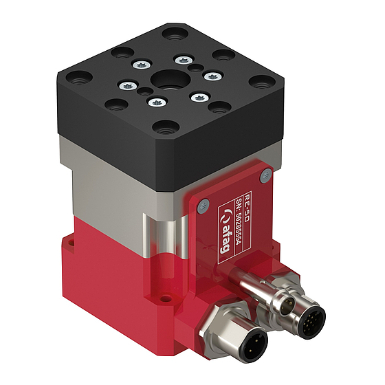
Module designation 1 Servo-drive with gearing 2 Encoder casing 3 Rotary flange 4 Encoder connection 5 Proximity switch 6 Motor connection 7 Mounting holes on the rear (see dimensions drawing) Figure 1: Module designation The RE rotary module consists of the servo-drive with gearing (1) with integrated electric motor. - Page 9 4 x 3.4 mm) while the RE-75 module is fitted in the 48 x 48 mm hole matrix with 4 M5 bolts (bolt circle 88 mm, through-hole 4 x 5.5 mm). The corresponding connection plates must be used for mounting the Afag modules. RE-75...
-
Page 10: Tightening Moments For Screw
Tightening moments for screw The screws to be used for assembly must at least satisfy the following conditions: Standard: VDI 2230 Strength: class 8.8 Surface: galvanized blue, oiled or greased Thread Tightening moments 0,3 … 0,35 Nm 0,5 … 0,73 Nm M2,5 1,1 …... - Page 11 WARNING Due to the decentral controller the operator of the RE rotary module needs not to be near the product so that third persons might be endangered by the rotation mode. Lock the controller while you are working on the RE rotary module and switch the controller only on again after work is finished.
-
Page 12: Preferred Combinations To Re-50
2.1.5 Preferred combinations to RE-50 RE-50-RE-75-OI-vers. 2.6 gb 28.07.14... -
Page 13: Preferred Combinations To Re-75
2.1.6 Preferred combinations to RE-75 RE-50-RE-75-OI-vers. 2.6 gb 28.07.14... -
Page 14: Montage Instructions
Directive 206/42/EG, Annex II B IV where appropriate. Name and address of the person authorised to compile the relevant technical docu- mentation: Lanz Beat, PM & Marketing-Services, Afag Automation AG RE-50-RE-75-OI-vers. 2.6 gb 28.07.14... -
Page 15: Scope Of Delivery
3.1.1 Scope of delivery Quantity Description 1 Module Centering bushings Ø 7x3.mm (RE-50) Mounting screw M3x22 mm (RE-50) Centering bushings Ø 9x4 mm (RE-75) Mounting screw M4x30 mm (RE-75) 1 Operating Instructions Table 2: Included in the delivery 3.1.2 Intended use The RE rotary modules are used for the smooth rotary movement of loads in non- explosion hazardous ambient and operating conditions that are specified for this module (see Technical Data). -
Page 16: Warranty
The module may only be deployed in accordance with the in- tended purpose. Modifications on the module that are not described in this Montage Instructions or have not been approved in writing by Afag are not permitted. In case of improper changes or assembly, installation, operation, maintenance or repairs, Afag AG rejects all liability. -
Page 17: Dimension Drawing Re-50 / Re-75
3.1.5 Dimension drawing RE-50 / RE-75 Figure 3: Dimension drawing RE-50 / RE-75 RE-50-RE-75-OI-vers. 2.6 gb 28.07.14... -
Page 18: Technical Data
3.1.6 Technical data IP 40 IP 40 IP 40 IP 40 Table 3: Technical data RE-50 / RE-75 RE-50-RE-75-OI-vers. 2.6 gb 28.07.14... -
Page 19: Rotary Module Electrical ( Without Flange)
3.1.7 Rotary module electrical ( without flange) RE-50-RE-75-OI-vers. 2.6 gb 28.07.14... -
Page 20: Flange Rotation
3.1.8 Flange rotation RE-50-RE-75-OI-vers. 2.6 gb 28.07.14... - Page 21 The large holes are not useful. Accessories to: RE-50 (without flange) Flange kit (incl. screw) Order No. 50294008 The large holes are not useful. Accessories to: RE-75 (without flange) Flange kit (incl. screw) Order No.: 50294009 RE-50-RE-75-OI-vers. 2.6 gb 28.07.14...
-
Page 22: Measured Values With
3.1.9 Measured values with 3.2.0 Installation of external Modules The rotary flange is designed for the attachment of Afag modules. If third party mod- ules are used the rotary flange can also be removed. The engineer can also manufacture a customized rotary flange which can be at- tached to third party modules. -
Page 23: Electrical Interfaces
3.2.1 Electrical interfaces Motor cable (M12 or M15) brown white 3 PE blue black Encoder cable (G10 or G12) brown blue withe green pink yellow black grey + 5 V violet grey/pink red/blue withe/green brown/green withe/yellow n.v. yellow/brown n.v. white/grey n.v. -
Page 24: Commissioning, Operation, Training
Sensor plug M5x0.5 3.1.2 Commissioning, Operation, Training WARNING Due to the rotating movement of the rotary flange garments, hair or other materials may be caught and drawn into the system while the module is being operated. Caution: Commissioning may only be executed by qualified person- nel. -
Page 25: Preparation For Commissioning
Use of the operating software is described in the Installation Instructions of the control system. If the RE rotary modules are delivered together with an Afag control system the op- erating parameters have already been stored on the controller. The RE rotary mod- ules can be started immediately. -
Page 26: Commissioning
3.1.4 Commissioning Carry out the first start-up slowly and step by step. Note the permissible technical data (see catalogue) regarding: useful load motion frequency moment load CAUTION Limbs may be crushed by moving components. Make sure that there are no persons or tools within the operating range of the module. -
Page 27: Normal Operation
3.1.6 Normal operation WARNING Due to the rotating movement of the rotary flange garments, hair or other materials may be caught and drawn into the sys- tem while the module is being operated. If add-ons at the RE rotary module could cause danger in con- nection with moving parts a safe operation must be ensured. -
Page 28: Maintenance Instruction
4.0.0 Maintenance Instructions 4.1.0 Maintenance and servicing WARNING Due to the rotating movement of the rotary flange garments, hair or other materials may be caught and drawn into the sys- tem while the module is being operated. Observe the Montage Instructions of the system into which the RE rotary module was incorporated. -
Page 29: Regular Maintenance
4.1.1 Regular maintenance Maintenance Maintenance work interval As required Clean the module with a dry, lint-free cloth. The module must not be washed down; do not use any ag- gressive cleaners. Table 4: Maintenance Additional maintenance Under the ambient conditions mentioned below the RE electric module does not re- quire any further maintenance: Clean workshop atmosphere No splash water... -
Page 30: Possible Failures
WARNING Due to the decentral controller the operator of the RE rotary module needs not to be near the product so that third persons might be endangered by the rotation mode. Always switch off the controller and protect it from being switched on again unintentionally when you work on the RE rotary module. -
Page 31: End Position Sensor Replacement
Sensor 4.1.6 Repair NOTE Repair of the RE rotary modules should only be carried out at Afag. There are no spare parts available. RE-50-RE-75-OI-vers. 2.6 gb 28.07.14... -
Page 32: Accessories
4.1.7 Accessories Type Order No. Centering bushings 7x3mm 11016850 see technical catalogue Centering bushings 9x4mm 11004942 Flange set RE-50 50294008 Flange set RE-75 50294009 Motor cable-M12-5m-0-open (SE-Power) 50290459 Motor cable-M12-10m-0-open (SE-Power) 50310506 Motor cable-M12-5m-90-open (SE-Power) 50290460 Motor cable-M12-10m-90-open (SE-Power) 50310507 Motor cable-M15-3m-0-0 (SE-24/48) 50332418 Motor cable-M15-3m-90-0 (SE-24/48) -
Page 33: Disassembly And Repair
4.1.8 Disassembly and repair When the module is damaged it can be returned to Afag Automation AG for repair. WARNING Before disassembly the power supply must be switched off and disconnected. Disassembly of the system may only be started after the power supply was definitely disconnected. -
Page 34: Annexe
Annexe 6.0.0 List of Figures Figure 1: Module designation ..................8 Figure 2: Installation and mounting options ..............9 Figure 3: Dimension drawing RE-50 / RE-75 ............17 6.1.0 List of Tables Table 1: Tightening moments for bolts ..............10 Table 2: Included in the delivery ................ - Page 35 RE-50-RE-75-OI-vers. 2.6 gb 28.07.14...
- Page 36 Afag Automation AG Fiechtenstrasse 32 4950 Huttwil Switzerland +41 (0)62 – 959 86 86 Tel.: +41 (0)62 – 959 87 87 Fax.: e-mail: sales@afag.com Internet: www.afag.com...
Need help?
Do you have a question about the RE Series and is the answer not in the manual?
Questions and answers