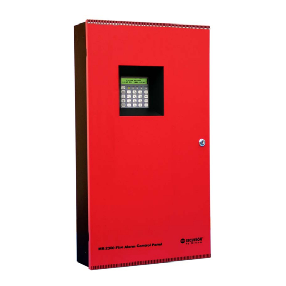
Secutron MR-2300 Series Installation And Operation Manual
Lcd fire alarm control panel
Hide thumbs
Also See for MR-2300 Series:
- Installation and operation manual (105 pages) ,
- Installation & operation manual (88 pages) ,
- User manual (20 pages)

Related Manuals for Secutron MR-2300 Series


Summary of Contents for Secutron MR-2300 Series
- Page 1 MR-2300 Series LCD Fire Alarm Control Panel LT-906SEC Rev. 3.2 Installation and Operation Manual January 2020...
-
Page 3: Table Of Contents
Contents Industry Canada and FCC Notice Notice for all MR-2300 Series Built-In UDACTs Sold in Canada ........Introduction Overall Features ......................Conventions Circuits ........................... Zone ..........................Events ..........................Wiring Styles ........................System Components, Sub-Assemblies & Accessories Main Fire Control Panel .................... - Page 4 Contents MR-2300-NC4/2 Output Class-A Converter Adder Module ........... Relay Adder Modules (Models MR-2312-R12 and MR-2306-R6) ........MR-2306-R6 Six Relay Adder Module ................Polarity Reversal and City Tie Module (Model MR-2300-PR) ........Field wiring Main Fire Alarm Board Field Wiring ................Relay Adder Module Wiring ..................
- Page 5 Contents 11.7 View Event Log (Command-Menu) ................11.8 Clear Event Log (Command-Menu) ................11.9 Walk Test (Command-Menu) ..................11.10 8. i3 Loop Test (Command-Menu) ................. 11.11 Dialer Config (Command-Menu) ..................11.12 Test Dialer (Command-Menu) ..................11.13 Bypass Det Ckt (Command-Menu) ................11.14 Bypass NAC Ckt (Command-Menu) ................
- Page 6 List of Figures Figure 1 Box dimensions, surface mount ..................Figure 2 MR-2312-DDR Box dimensions, semi-flush mounting with trim ring ......Figure 3 Flush Trim Detail\ ......................Figure 4 MR-2306-DDR/MR-2306-DR Box dimensions, mounting and trim ring ......Figure 5 MMX-BBX-1024DS and MMX-BBX-1024DSR Installation Instructions and Dimensions Figure 6 Installation of Adder Modules for MR-2312 LCD Panels ..........
- Page 7 List of Figures Figure 44 Account info menu ......................Figure 45 Telephone Line menu ....................Figure 46 Report Options menu ..................... Figure 47 Time Parameters ......................Figure 48 Detection circuit message ....................Figure 49 Indicating circuit message ....................Figure 50 AC Power Fail message ....................Figure 51 Battery trouble message ....................
- Page 8 List of Tables Table 1 Connectors and Jumpers on the Main Fire Alarm Board ..........Table 2 Jumpers on the Core Board ................... Table 3 MR-2300-PR jumper settings ..................Table 4 Power Supply Ratings ....................Table 5 Initiating Circuit Wiring ....................Table 6 Indicating Circuit Wiring ....................
-
Page 9: Industry Canada And Fcc Notice
Users should not attempt to make such connections themselves, but should contact the appropriate electric inspection authority, or electrician, as appropriate. 1.1.2 Notice for all MR-2300 Series Built-in UDACTs Sold in the U.S.A. Note: The Ringer Equivalence Number (REN) assigned to each terminal device provides an indication of the maximum number of terminals allowed to be connected to a telephone interface. - Page 10 Contact your telephone company if you have any questions about your phone line. In the event repairs are ever needed on the Communicator, they should be performed by Secutron Fire Alarm System’s or an authorized representative of Secutron Fire Alarm System. For information contact Secutron Fire Alarm System at the address and phone numbers shown on the back page of this document.
-
Page 11: Introduction
Introduction Secutron's MR-2300 Series Fire Alarm Control Panel is a Digital Signal Processor (DSP) based fire panel. The MR-2300 provides a maximum of 12 supervised Class B or A (Style B or D) Initiating circuits, and maximum of four supervised Class B or A (Style Y or Z) indicating circuits. -
Page 12: Conventions
Conventions Circuits Refers to an actual electrical interface for Initiating (Detection) and Indicating (Signal) or Relays. Zone Is a logical concept for a Fire Alarm Protected Area, and will consist of at least one Circuit. Often the terms Zone and Circuit are used interchangeably, but in this Manual the term Circuit is used. -
Page 13: System Components, Sub-Assemblies & Accessories
System Components, Sub- Assemblies & Accessories Main Fire Control Panel Model Description Twelve-Zone Fire Alarm Control Panel with LCD display and dialer (red door, black box). 12 Class B (Style B) Initiating circuits, and four Power Limited Class B (Style Y) Indicating circuits (up to 1.70 amperes each, 5 amperes total). -
Page 14: Relay Module: 12 Relays
SYSTEM NORMAL 18:01 MON 2003-04-05 A.C. ON ALARM SUPV TRBL CPU FAIL SYSTEM RESET Remote Annunciator Module, LCD display, red SIGNAL 7.2" ENTER SILENCE MR-2300-LCDR FIRE MENU DRILL enclosure BUZZER CANCEL SILENCE LAMP INFO TEST 1.25" MR-2300 SERIES Remote Annunciator... -
Page 15: Smart Relay Module
Model Description MR-2312-SR12/ Smart Relay Module (12 relays) with red or white enclosure MR-2312-SW12 MR-2300 SERIES REMOTE RELAY Input Class A converter: Six Circuits Model Description Input Class A converter Module (six circuits). This MR-2300-A module has built in Active End-of-Line resistors... -
Page 16: 4.10 Active End-Of-Line
System Components, Sub-Assemblies & Accessories 4.10 Active end-of-line The MR-2300-X are power-saving End-of-Line resistors that eliminate the need for an additional battery cabinet or larger batteries in order to meet the 60 hour standby requirement. Model Description MR-2300-X Active end-of-line resistor without plate BLACK 4.11 MR-2312-AT Remote Annunciator Model... -
Page 17: Mechanical Installation
Mechanical Installation Installing the Enclosure Install the MR-2300 Series Fire Alarm Panel enclosure as shown below for the twelve zone models. Mount enclosure surface mount using the four mounting holes, as shown and the screws provided. The backbox may be semi-flush mounted using the trim ring model MR- 2312-FT (BLACK), see Figure 2. -
Page 18: Figure 2 Mr-2312-Ddr Box Dimensions, Semi-Flush Mounting With Trim Ring
Mechanical Installation 11" 1.5" PLACE MR-2312-FT TRIM RING OVER BACKBOX 17" 20.5" 26" Adhere trim ring to 28.5" wall surface around MR-2306 backbox. 5.4" 3.5" 1" 14.5" 3.5" is the maximum depth for semi-flush 1" is the minimum depth mounting using the above the wall required for flush trim ring semi-flush mounting using the... -
Page 19: Figure 4 Mr-2306-Ddr/Mr-2306-Dr Box Dimensions, Mounting And Trim Ring
Mechanical Installation 11" 1.5" PLACE MR-2306-FT TRIM RING OVER BACKBOX 17" 4 Mounting Holes for Surface 14.5" Mounting 20.0" Adhere trim ring to wall surface around 22.5" the MR-2306 backbox. 5.425" 3.5" 1" 14.5" 3.5" is the maximum depth 1" is the minimum depth for semi-flush mounting above the wall required using the flush trim ring... -
Page 20: Mmx-Bbx-1024Ds And Mmx-Bbx-1024Dsr Mechanical Installation
Mechanical Installation MMX-BBX-1024DS and MMX-BBX-1024DSR Mechanical Installation The MMX-BBX-1024DS and MMX-BBX-1024DSR are suitable for flush or surface mounting, and have a built-in trim ring. Dimensions of Enclosure (minus built in trim ring) 14.5” x 4.2” x 26” Distance between horizontal mounting screws 12”... -
Page 21: Installing The Adder Modules
Mechanical Installation Installing the Adder Modules MR-2300 Series Fire Alarm panels come pre-assembled with all components and boards except for Adder Modules. Module installation locations are shown below. Refer to Figure 8 and Figure 9 for Jumper or DIP Switch settings and see “Field wiring” on page 29 for wiring information. -
Page 22: Figure 7 Installation Of Adder Modules For Mr-2306 Lcd Panels
Mechanical Installation MAIN FIRE PANEL BOARD CLASS-A converter board for detection circuits MR-2300-A LCD configuration (6 circuits ) tool - CFG-300 plugged into the LCD DISPLAY socket shown. SYSTEM NORMAL CLASS-A converter 18:01 MON 2003-04-05 board for indicating circuits MR-2300-NC2 A.C. -
Page 23: Dip Switch And Jumper Selections For Main Board And Adder Modules
DIP Switch and Jumper Selections for Main Board and Adder Modules Main Fire Alarm Board For PC programming use SUIMA interface module not UL-864 or Main Fire Alarm Board Core Board ULC-S527 listed. JW4 -Normally closed JW5 -Normally open Telephone line Telephone line JW7- Always Open S Y S T E M N O R M A L... -
Page 24: Figure 9 Main Fire Alarm Board Dip Switch And Jumper Settings For Mr-2300 Lcd Panels
DIP Switch and Jumper Selections for Main Board and Adder Modules For PC programming use SUIMA interface module not UL-864 or ULC-S527 listed. Main Fire Alarm Board Core Board JW4 -Normally closed JW5 -Normally open Telephone line Telephone line Always open S Y S T E M N O R M A L RS-485 for 1 8 : 0 1 M O N 2 0 0 3 - 0 4 - 0 5... -
Page 25: Mr-2300-A Input Class-A Converter Adder Module
DIP Switch and Jumper Selections for Main Board and Adder Modules Table 2 Jumpers on the Core Board Leave closed (on). Leave open (off). MR-2300-A Input Class-A Converter Adder Module MR-2300-A mounting hole for #6-32 screws All these pins comes with red and black wires which are connected to the detection circuit on the... -
Page 26: Mr-2300-Nc4/2 Output Class-A Converter Adder Module
DIP Switch and Jumper Selections for Main Board and Adder Modules MR-2300-NC4/2 Output Class-A Converter Adder Module mounting hole for mounting hole for #6-32 screws #6-32 screws MR-2300-NC4 MR-2300-NC2 mounting hole for #6-32 screws mounting hole for #6-32 screws Figure 11 MR-2300-NC4/2 Output Class-A Converter Adder Module Indicating circuits must be wired from the MR-2300-NC4/2 to the main Fire Alarm board. -
Page 27: Mr-2306-R6 Six Relay Adder Module
DIP Switch and Jumper Selections for Main Board and Adder Modules 6.4.2 Programming the relays A typical relay circuit is shown below in Figure 13 with the jumper locations and descriptions. Note: Relay programming should be done before installing the board. ZONE JUMPER installed: turns ON relay when the zone (1) is active... -
Page 28: Polarity Reversal And City Tie Module (Model Mr-2300-Pr)
DIP Switch and Jumper Selections for Main Board and Adder Modules P1: Cable from MR-2306-R6 Relay Adder Module connects to P6 on the Main Fire Alarm Board. 6.5.1 Programming the relays See explanation in Figure 13. Note: Relay programming should be done before installing the board. Polarity Reversal and City Tie Module (Model MR-2300-PR) Mounting hole for #6-32 screws... -
Page 29: Field Wiring
Field wiring Main Fire Alarm Board Field Wiring Wire devices to the terminals as shown in the figures that follow. Refer to the Wiring Tables for wire gauges and to Appendix A for specifications. Caution: Do not exceed power supply ratings. 7.1.1 Initiating Circuit Wiring Wiring diagrams for the initiating circuits are shown below. -
Page 30: Figure 17 Initiating Circuit- Class A Or Style D Wiring
Figure 17 Initiating circuit– Class A or Style D wiring 7.1.2 Indicating Circuit Wiring The MR-2300 Series Fire Alarm supports Class B (Style Y) and Class A (Style Z) wiring for its indicating circuits. Each circuit is supervised by a 3.9K End-of-Line resistor. Each indicating circuit provides up to 1.7 A, 5 A maximum total if no auxiliaries are used. -
Page 31: Figure 18 Indicating Circuit - Class B Or Style Y Wiring
Field wiring FIRE ALARM MAIN BOARD STYLE Y WIRING INDICATING INDICATING CIRCUIT - 1 CIRCUIT #1 INDICATING STYLE Y CIRCUIT #2 WIRING INDICATING CIRCUIT - 2 BELL STROBE HORN 3.9K 1/2 WATT ELR Figure 18 Indicating circuit – Class B or Style Y wiring SOCA-204 CLASS A MR-2300-NC4 STYLE Z... -
Page 32: Figure 20 Four-Wire Smoke Detector Wiring
Field wiring 7.1.3 Four Wire Smoke Detector Wiring FIRE ALARM MAIN BOARD POWER RESETTABLE 4-WIRE SMOKE DETECTOR POWER SUPPLY 22VDC, 200mA MAX. CURRENT - 300mA MAX. RIPPLE VOL. 5mV (POWER LIMITED) DETECTION END OF LINE RELAY 4-WIRE DETECTION DEVICE LISTED S3403 MODEL A77-716B TO INITIATING MANUFACTURED BY... -
Page 33: Relay Adder Module Wiring
Field wiring Relay Adder Module Wiring Wire relays on the relay adder modules MR-2312-R12 and MR-2306-R6 as shown in Figures 19 and 20. RM-312 12 RELAY ADDER MODULE NORMALLY OPEN RELAY NORMALLY OPEN OR CONNECTION CIRCUIT #1 NORMALLY CLOSED NO/NC CONNECTION IS SELECTED BY JUMPER NORMALLY CLOSE... -
Page 34: Figure 24 Connecting An Facp To A 3G4010Cf Interface Device
Field wiring Connecting to a 3G4010CF Interface Device For information on Compatible Receivers see “Appendix A: Compatible Receivers” on page 85. A typical connection is shown in Figure 24. The 3G4010CF is powered separately from the PCS-100 and requires 2 DSC RM-2 relays (sold separately). The PCS-100 Passive Communications Interface Board (sold separately) is also required. -
Page 35: Polarity Reversal And City Tie Module (Mr-2300-Pr) Wiring
Field wiring Polarity Reversal and City Tie Module (MR-2300-PR) Wiring Wire MR-2300-PR Polarity Reversal and City Tie Module (if used) as shown in Figure 25, below. See “Appendix A: Compatible Receivers” on page 85 for module specifications. Power Limited cable type FPL, FPLR or FPLP must be used. For USA installation, the installer must use Atlantic Scientific (Tel: 407-725-8000), Model #24544 Protective Device, or similar UL-Listed QVRG secondary protector, as shown. -
Page 36: Figure 26 Power Supply Connection
Field wiring Wire as shown below in Figure 26 using the proper wire gauge. See “Appendix A: Compatible Receivers” on page 85 for power supply specifications. Note: Do not exceed power supply ratings. J W 1 red red BATTE RY SEC. -
Page 37: Wiring Tables And Information
Field wiring Wiring Tables and Information Table 5 Initiating Circuit Wiring Wire gauge Maximum wiring run to last device Feet Meters 2990 4760 1450 7560 2300 12000 3600 19000 5800 30400 9200 Note: For Class A the maximum wiring run to the last device is divided by two. Maximum loop resistance should not exceed 100 ohms. -
Page 38: Supervised Auxiliary Power (Regulated)
Field wiring Supervised Auxiliary Power (regulated) Supervised auxiliary power is used to power the remote annunciators and smart relay modules. This filtered circuit is supervised, therefore a short will disconnect the power through the relay until the “RESET” key is pressed. This supply is rated at 22.3VDC regulated/500mA max/1V voltage drop maximum. -
Page 39: Turning On The Panel
Turning on the Panel Before Connecting the Power 1. To prevent sparking, do not connect the batteries. Connect the batteries after powering the system from the main AC supply. 2. Check that all modules are installed in the proper location with the proper connections. 3. -
Page 40: Figure 27 Power Supply Connection
Turning on the Panel J W 1 red red BATTE RY SEC. TX black Connect AC power here: white black white wire to L green green wire to G white black black wire to N white Battery Battery NOTE: TO PREVENT SPARKING, CONNECT BATTERIES AFTER THE SYSTEM MAIN A.C. -
Page 41: Troubleshooting
Turning on the Panel Troubleshooting Table 7 Troubleshooting Symptoms Possible Cause (as displayed on the LCD) Normally when a circuit trouble occurs, the common trouble indicator will illuminate and trouble buzzer will sound. To correct the fault, check for open wiring on that Circuit Trouble particular circuit loop (as displayed on the LCD) or that the circuit has not been disconnected (or bypassed). -
Page 42: Indicators, Controls And Operations
Indicators, Controls and Operations Refer to Figure 28 below which shows the LCD Display, the Keypad and Control Button locations. S Y S T E M N O R M A L 1 8 : 0 1 M O N 2 0 0 3 - 0 4 - 0 5 A.C. -
Page 43: Common Indicators
Indicators, Controls and Operations Common Indicators 9.1.1 Buzzer The Buzzer is activated by any of the following events: Fire Alarm: Steady Supervisory Alarm: Fast Flash Trouble: Trouble Flash Rate If the Buzzer is turned ON in response to a Non-Latching Trouble or Supervisory, it will be turned OFF if the condition causing it goes away and there is no other reason for it to be ON. -
Page 44: Common Controls
Indicators, Controls and Operations To test the CPU FAIL LED 1. Disconnect AC and batteries from the main board. 2. Connect AC and then connect the batteries as described in “Turning on the Panel” on page 39. If the CPU FAIL LED is functioning properly, it will flash once when the board powers up. Common Controls 9.2.1 System Reset Button The System Reset button resets the Fire Alarm Control Panel and all circuits. -
Page 45: Common Relays
Indicators, Controls and Operations Press and hold the LAMP TEST for 3 seconds to show the information about the system and the firmware version. The first line shows the number of zones and panel type and the second line shows the software version number. 9.2.5 Buzzer Silence Button Activation of the Buzzer Silence button while the Buzzer is sounding silences the Buzzer. -
Page 46: Circuit Types
Indicators, Controls and Operations Table 9 Feature Config Menu on page 57). When configured, the relay can also be disconnected if signal silence is active and reconnected if signal silence is de-activated. Note: Each relay has an LED beside it. These LEDs are used for diagnostic purposes. Circuit Types 9.4.1 Initiating (Detection) Circuit Types 9.4.2 Non-Verified Alarm... - Page 47 Indicators, Controls and Operations interval, the water flow alarm is confirmed and processed. An alarm condition causes the Common Alarm LED to illuminate red. Note: Do not use Retard Operation with any external retarding device; maximum retard may not exceed 120 seconds. 9.4.6 Non-Latching Supervisory (For Supervisory Circuits) An activation on these circuits will cause the amber Common Supervisory LED to illuminate.
-
Page 48: Evacuation Codes
Indicators, Controls and Operations 9.4.14 Non-Silenceable Strobes Non-Silenceable Strobes will not be silenced when the “signal silence” key is pressed. For synchronous strobes see section 10 on page 50. (Note: Strobes do not support any code pattern.) Evacuation codes ContinuousOn 100% of the time Temporal Code3 of 0.5 second on, 0.5 second off then, 1.5 second pause March Code0.5 second on, 0.5 second off California Code5 seconds on, 10 seconds off... -
Page 49: Fire Alarm Operation
Indicators, Controls and Operations Fire Alarm Operation In a basic system set up all alarm inputs are treated in a similar manner. Alarm inputs include any of the following: Non-Verified Alarm, Verified Alarm, Sprinkler Alarm, and Water flow Alarm. If any of these alarm inputs occur when the panel is not already in alarm, the following occurs: •... -
Page 50: Supported Protocols/Devices
10.0 Supported Protocols/Devices 10.1 Synchronous Strobes The synchronous strobe models that are supported by the MR-2300 panel include Secutron models MRL-ST and MRA-HS. A separate compatibility list is available for different supported models. Strobes can be configures as normal (e.g. not synchronized or any of the above; section 11 on page 53). - Page 51 Supported Protocols/Devices 10.3.1 i zone Troubles The following troubles can be reported for a zone configured as i zone: • Open circuit trouble • Communication trouble • Out of sensitivity: defective or dirty device • Freeze trouble 10.3.2 Open circuit trouble If the loop is broken the panel shows open loop trouble.
-
Page 52: Table 8 I3 Detector Status
Supported Protocols/Devices 10.3.6 Freeze trouble If the device has detected a freeze condition, (e.g. the temperature is below 41F / 5 C) then the panel will show a freeze trouble. Only model 2WT-B is capable of thermal detection; model 2W-B does not indicate any freeze trouble. Z o n e - 1 F r e e z e T r b . -
Page 53: Configuration
11.0 Configuration There are three methods of configuring the MR-2300 LCD Series Fire Alarm Panels: • Direct configuration using the main LCD display and the menu buttons. • Using a PC or Lap Top Computer with a UIMA converter module. •... -
Page 54: 11.2 Command Menu
Configuration 11.1 Accessing Configuration Mode To access configuration mode 1. Press the Menu button on the front panel display. 2. Enter your passcode. The minimum number of digits for the passcode is four and the maximum is ten. The passcode must be numerical values only. The default passcode is 1111. 3. -
Page 55: Figure 32 Command Menu
Configuration -Command Menu- 1. MR-2306 Config 2. Config Info 3. Set Time 4. Set Password 5. View EventLog 6. Clear EventLog 7. Walk Test 8. I3 Loop test 9. Dialer Config 10.Test Dialer 11.Bypass Det Ckt 12.Bypass NAC Ckt 13.Aux Disc 14.Exit Figure 32 Command Menu 11.2.1 Using the Keypad to Program the FA-300... -
Page 56: Panel Config (Command-Menu)
Configuration 11.3 Panel Config (Command-Menu) The MR-2300 configuration menu is shown in Figure 33. MR-2300 Figure 33 MR-2300 Config menu 11.3.1 Feature Config Select Features to access the Feature Config menu shown in Figure 34. - Featu re Config - 1 Man. -
Page 57: Table 9 Feature Config Menu
Configuration Table 9 describes the options in the Feature Config menu. Table 9 Feature Config Menu Name in the Feature Default Description Configuration Utility Command Menu/MR-2300 Config/Features/ 1. Manual Signal Silence Use this function to enable or [X] ENABLE->Default Manual signal disable the SIGNAL SILENCE silence [ ] DISABLE... - Page 58 Configuration Table 9 Feature Config Menu (Continued) Name in the Feature Default Description Configuration Utility Command Menu/MR-2300 Config/Features/ [X] DISABLE->Default Use this function to inhibit the 6.Signal-Silence Inhibit timer SIGNAL SILENCE switch for [ ] 10 SEC a desired length of time. This Signal silence [ ] 20 SEC time period should expire...
- Page 59 [X] NORMAL ->Default used in the system. The 14.Strobe Type selection is system-wide and [ ] SECUTRON applies to all indicating circuits [ ] FARADY S t r o b e T y p e configured as strobes. For...
- Page 60 Configuration Command Menu-->MR-2300 Config Note: Refer to section 11.2.1 on page 55 for detailed instructions on making menu selections. 11.3.2 Inp Zone I n i t i a t i n g Z o n e 1 Z o n e - 1 2 Z o n e - 2 1 2 Z o n e 1 2 This menu is used to program the process type for the initiating circuits.
- Page 61 Configuration Command Menu-->MR-2300 Config Note: Refer to section 11.2.1 on page 55 for detailed instructions on making menu selections. 11.3.4 Opt Zone I n d i c a t i n g Z o n e 1 N A C - 1 2 N A C - 2 3 N A C - 3 4 N A C - 4...
- Page 62 Configuration Command Menu-->MR-2300 Config Note: Refer to section 11.2.1 on page 55 for detailed instructions on making menu selections. 11.3.6 Inp Zone Label I n i t i a t i n g Z o n e 1 Z o n e - 1 2 Z o n e - 2 1 2 Z o n e 1 2 Use the keypad described below for entering a message.
- Page 63 Configuration Command Menu-->MR-2300 Config Note: Refer to section 11.2.1 on page 55 for detailed instructions on making menu selections. 11.3.7 Opt Zone Label I n d i c a t i n g Z o n e 1 N A C - 1 2 N A C - 2 3 N A C - 3 4 N A C - 4...
-
Page 64: Config Info (Command-Menu)
Configuration Command Menu-->MR-2300 Config 11.3.8 Default Configuration L o a d t h e d e f a u l t s e t t i n g s ? Y Use this menu to load the default configuration in the panel. Press “UP”... -
Page 65: Set Time (Command-Menu)
Configuration 11.5 Set Time (Command-Menu) Note: Refer to section 11.2.1 on page 55 for detailed instructions on making menu selections. 1 Daylight Save 2 Time Clock 3 Compensation Command Menu/Set Time 11.5.1 Daylight saving [X] DISABLE ->Default Use this function to enable daylight savings time. -
Page 66: Set Password (Command-Menu)
Configuration 11.6 Set Password (Command-Menu) Note: Refer to section 11.2.1 on page 55 for detailed instructions on making menu selections. Enter new passcode Re-enter passcode If the passcode does not match, the Use this function to change the following message appears and the passcode. -
Page 67: Clear Event Log (Command-Menu)
Configuration 11.8 Clear Event Log (Command-Menu) Note: Refer to section 11.2.1 on page 55 for detailed instructions on making menu selections. -Select Log- 1 Alarm Log 2 General Log 3 All Logs Select the type of log to clear. Press the ENTER button. -
Page 68: I3 Loop Test (Command-Menu)
Configuration buttons to scroll through the zones and use the left and right arrow buttons to select a zone. Press the ENTER button when you are done with all the selections. - W A L K T E S T Z O N E S - [ ] Z o n e - 1 Figure 37 Walk test zones The walk test is now active (see Figure 38) -
Page 69: Figure 39 I3 Loop Test Confirmation
Configuration inquiries. An i maintenance test can be invoked from the command menu. If the fire alarm has just been powered up or reset, wait six minutes before selecting the i loop test. If the i loop test is selected, the following message appears on the screen: P e r f o r m t h e i 3 L o o p t e s t ? Y Figure 39 i... -
Page 70: Dialer Config (Command-Menu)
Configuration Table 10 Detector LEDs while in test mode (Continued) Green LED Red LED Detector Condition Freeze condition Double blink every10 sec You can cancel the maintenance test either by pressing the RESET button or by going into section 11 on page 53 and canceling the test. 11.11 Dialer Config (Command-Menu) Note: Refer to section 11.2.1 on page 55 for detailed instructions on making menu... - Page 71 Configuration Use this menu to set the Account Command Menu/Dialer Config/Account Info ID for the monitoring station to which the dialer reports events. 1.Account# 1 Identification The maximum # of digits allowed is six. For contact ID, only the first four digits are used;...
-
Page 72: Figure 45 Telephone Line Menu
Configuration Command Menu/Dialer Config/Account Info 6.Account# 2 Reporting Format [X] Contact ID-Def Same as Account#1. [ ] SIA 300 Baud [ ] SIA 110 Baud A C C N T # 2 F o r m a t : [ X ] C o n t a c t I D Command Menu-->Dialer Config 11.11.2Telephone Line - T e l e p h o n e L i n e -... -
Page 73: Figure 46 Report Options Menu
Configuration Command Menu/Dialer-Config/Telephone Line Set the number of retries for both 5.Number of retries line#1 and line#2. This function lets the dialer retry on either line if it is 06 ->Default busy or not available. If the retry count expires, the panel reports a N u m b e r o f R e t r i e s : line trouble. -
Page 74: Figure 47 Time Parameters
Configuration Command Menu/Dialer-Config/Report Options If this function is enabled, 4.Aux Disconnect, Cancels Alarm & the “Aux Disconnect” feature Supv Reporting Thru dialer (Command Menu, as a [ ] ENABLE switch) will block the alarm [X] DISABLE ->Default and supervisory events from being reported through the AuxDis Alm&Supv Rpt. -
Page 75: Table 11 Auto Test Time And Cellular Report Date
Configuration Use this function to set the time for Command Menu/Dialer-Config/Time Parameter the automatic test. When this test is performed, the test report is sent to 3.Auto test time the monitoring station. This test must be performed at least once a day. -
Page 76: Test Dialer (Command-Menu)
Configuration Command Menu-->Dialer-Config Ring Detect Use this menu item to select the [ ] Disabled number of rings on which the [ ] 1 panel’s modem will answer. The [ ] 2 default number of rings is five. The -Ring Detect Number - [ ] 3 maximum number of rings you can [X]5... - Page 77 Configuration 11.12.1Dialer Test Messages The following messages will display during the test processes of Lines #1 and #2. The messages that will appear depend on the status of the dialer and the test results that are found. The dialer is checking the line for voltage. This Dialer idle now message automatically displays when Manual Test is selected.
-
Page 78: Bypass Det Ckt (Command-Menu)
Configuration Passed: Manual test The line passed the test; everything is OK. 11.13 Bypass Det Ckt (Command-Menu) Note: Refer to section 11.2.1 on page 55 for detailed instructions on making menu selections. Initiating zones may be bypassed individually. This Bypass Det Zone bypass command will allow you to scroll through all initiating zones 1 to a maximum of 12 depending on the 1.Zone-1... -
Page 79: Aux. Disconnect (Command-Menu)
Configuration 11.15 Aux. Disconnect (Command-Menu) Use the up or down keys to change from YES to NO. Disconnect Aux This selection work like a switch. If Yes this command disconnects the auxiliary alarm relay and associated Relay?[Y] relays as long as the Aux disc feature has be enabled. 11.16 Exit (Command-Menu) Note: Refer to section 11.2.1 on page 55 for detailed instructions on making menu... -
Page 80: Figure 48 Detection Circuit Message
Configuration 11.16.2Example 1 (detection circuit) Event 02 of 09, OPEN TRB on initiating circuit Z-01 in the EAST LOBBY ENTRANCE with process type as VERIFIED ALARM and the event occurred on 2003/02/02 at 18:01 TUESDAY. Z O N E P ro c ess P h ysic al M essag e T yp e... -
Page 81: Figure 50 Ac Power Fail Message
Configuration 11.16.4AC Power Fail The AC power fail trouble is generated when the power drops below the UL specified value. The trouble is restored when the power returns to the normal value. T ro u b le c o d e T ro u b le In fo T ro u b le T yp e A C P o w e r F a i l... -
Page 82: Figure 52 Ground Fault Message
Configuration 11.16.6Ground Fault T ro u b le co d e T ro u b le In fo T ro u b le T yp e G r o u n d F a u l t T r b : 0 x 0 3 I n f o : 0 x 0 0 0 1 "I N F O "... -
Page 83: Figure 54 Four-Wire Smoke Detector Supply Message
Configuration 11.16.8Four-wire smoke detector supply The four-wire smoke detector supply is supervised for shorts. When a short is detected on the four-wire smoke supply the power is cut off and a trouble message is generated. Press the system RESET button to restore power to the system. If the short is removed, the panel will return to normal;... -
Page 84: Figure 56 Module Missing Message
Configuration 11.16.10City tie Polarity reversal - MR-2300-PR Relay module The city tie or polarity reversal module is supervised for open and whether or not the MR- 2300-PR is plugged in. The relay module is supervised for whether or not it is plugged in. If any of the modules are not plugged in, the following trouble message is generated: T ro u b le co d e T ro u b le In fo... -
Page 85: Appendix A: Compatible Receivers
12.0 Appendix A: Compatible Receivers The dialers that are built into select models of the MR-2300 Series Fire Alarm Control Panels are compatible with the following Digital Alarm Communicator Receivers (DACR): DACR Receiver Model Protocols SurGard MLR2 Multi-Line Receiver (ULC, ULI approved) -
Page 86: Appendix B: Reporting
13.0 Appendix B: Reporting 13.1 Ademco Contact-ID 13.1.1 MR-2300 Event Codes Event Description Event Family Qualifier Code Group # Contact # Phone Line #1 trouble detected Trouble New event 1 351 Phone Line #2 trouble detected Trouble New event 1 352 Phone Line #1 trouble restored Trouble Restore... -
Page 87: 13.2 Security Industries Association Sia-Dcs
Appendix B: Reporting 13.2 Security Industries Association SIA-DCS SIA protocol does not define indicating zone troubles, but lists it as Untyped Zone Trouble/ Restore. 13.2.1 MR-2300 Event Codes Event Event Description Event Family Qualifier Parameter Code Phone Line #1 trouble detected Trouble New event Phone Line #2 trouble detected... -
Page 88: Appendix C: Specifications
14.0 Appendix C: Specifications Table 12 MR-2300 LCD Series Specifications MR-2300 LCD Fire Control Panel Chassis General Digital Signal Processor (DSP) based design. Fully configurable using front panel LCD display with Password Access. Indicating (NAC) 4 supervised Style Z (Class B) indicating circuits, configured as strobes or Circuits audibles. - Page 89 Appendix C: Specifications Table 12 MR-2300 LCD Series Specifications (Continued) MR-2300 LCD Fire Control Panel Chassis Battery Type 24 VDC (2x12 VDC), sealed lead acid, 6 Ah maximum Charging capability 10 Ah Protection 10 A on board (F1) slow blow micro fuse Compliance System Model FA-300 Series LED Version Fire Alarm Control...
-
Page 90: Table 13 Fa-300 Lcd System Modules And Annunciators
Appendix C: Specifications Table 13 FA-300 LCD System Modules and Annunciators (Continued) MR-2300 LCD Series Modules and Annunciators MR-2300-PR Polarity Reversal and City Tie Module City Tie power limited / 24 VDC unfiltered / 250 mA Ω max / 14 trip coil Polarity Reversal power limited / 24 VDC open / 12 VDC at... -
Page 91: Appendix D: Power Supply And Battery Calculations (Selection Guide)
15.0 Appendix D: Power Supply and Battery Calculations (Selection Guide) Use the form below to determine the required secondary power supply (batteries). IMPORTANT NOTICE The main AC branch circuit connection for Fire Alarm Control Panel must provide a dedicated continuous power without provision of any disconnect devices. - Page 92 ([STANDBY (A) ______ ] X [(24 or 60 Hours) ___ ]) + ([ALARM (B) ______ ] X [ ' Alarm in Hr.] _____) = (C) ______AH Total Alarm Current: Must be 6 amperes or less for MR-2300 Series. Indicating Circuits must not exceed 5 amperes.
-
Page 93: Warranty And Warning Information
Please read this document CAREFULLY, as it contains important warnings, life-safety, and practical information about all products manufactured by the Mircom Group of Companies, including Mircom and Secutron branded products, which shall include without limitation all fire alarm, nurse call, building automation and access control and card access products (hereinafter individually or collectively, as applicable, referred to as “Mircom System”). - Page 94 Warranty and Warning Information The testing should include all sensing devices, keypads, consoles, alarm indicating devices and any other operational devices that are part of the system. NOTE TO USERS: All Mircom Systems have been carefully designed to be as effective as possible. However, there are circumstances where they may not provide protection.
- Page 95 Warranty and Warning Information 13. Wireless Devices Placement Proximity. Moreover all wireless devices must be a minimum and maximum distance away from large metal objects, such as refrigerators. You are required to consult the specific Mircom System manual and application guide for any maximum distances required between devices and suggested placement of wireless devices for optimal functioning.
- Page 96 U.S.A CANADA - Main Office © Secutron 2020 25 Interchange Way 4575 Witmer Industrial Estates Printed in Canada Subject to change without prior notice Niagara Falls, NY 14305 Vaughan, ON L4K 5W3 Tel: (888) 660-4655 Tel: (888) 660-4655 www.secutron.com...
Need help?
Do you have a question about the MR-2300 Series and is the answer not in the manual?
Questions and answers