
Related Manuals for Secutron MR-2605


Summary of Contents for Secutron MR-2605
- Page 1 MR-2605 Five Zone Fire Alarm Control Panel Installation Manual © Secutron LT-2016 Rev.4 July 2010...
-
Page 3: Table Of Contents
Table of Contents Introduction The MR-2605 Fire Alarm Control Unit ................1.1.1 General features ......................1.1.2 Applications ........................Codes, Standards and Installation Requirements ............1.2.1 Relevant codes and standards ..................1.2.2 General Installation requirements ................... Technical Support and General Information .............. - Page 4 Relay Function ....................... 5.10.1 Alarm Relay ........................5.10.2 Trouble Relay ......................... 5.10.3 Supervisory Relay (available with the MR-2605-R3 Relay Expander only) ....MR-2605 System Programming Entering Installer Programming Mode ................6.1.1 Using the LED Indicators to Program the System ............6.1.2 Using the Silence Trouble and Silence Alarm Controls to Program the System ....
- Page 5 Startup of the MR-2605 Prior to power up ......................Power up sequence ......................Default Operation ......................Programming the Panel ....................Final Verification ......................Programming Worksheets Entering the Installer Programming Mode ..............Zone Programming ......................NAC Temporal/Steady Programming (Section 1) ............
- Page 6 Secutron Inc.
- Page 7 List of Figures Figure 1 MR-2605 cabinet with door closed ................. Figure 2 MR-2605 display and controls ..................Figure 3 MR-2605 Cabinet Overview ................... Figure 4 Zone Label Insert ......................Figure 5 Panel Assembly and Modules Locations ................ Figure 6 Mounting Dimensions .....................
- Page 8 Secutron Inc. viii...
- Page 9 Table 1 Electrical Specifications ....................Table 2 Module Current Ratings ....................Table 3 Battery Calculation Chart ....................Table 4 MR-2605 Terminal Descriptions ..................Table 5 Zone Wiring Chart ......................Table 6 NAC Wiring Chart ......................Table 7 Secur-bus Wiring Chart ....................
- Page 10 Secutron Inc.
-
Page 11: Introduction
Cabinet with dead-front construction • Transformer, mounted in the cabinet 1.1.2 Applications The MR-2605 five zone, fire alarm control panel is listed for use in the following applications. • Protected Premises Fire Alarm System And for the following types of service: A –... -
Page 12: Technical Support And General Information
Compatible devices Use UL or ULC Listed smoke detectors and notification appliances that are compatible with the MR-2605 Fire alarm control panel from the lists included in this manual. 1.3 Technical Support and General Information For technical support call 1--888-SECUTRON, or email techsupport@secutron.com. -
Page 13: Preparing To Install The Mr-2605 Fire Panel
Preparing to Install the MR-2605 Fire Panel 2.1 Unpacking the MR-2605 The basic MR-2605 package includes the following components: • Cabinet with hinged door • Display and control plate c/w display and control printed circuit board. • Zone label insert •... -
Page 14: Optional Accessories
2.2 Optional Accessories Model Number Name Description MR-2605-R3 Relay module Provides 3 relays that are jumper programmable to activate on common ‘alarm’, ‘supervisory’ or ‘trouble’. Mounts inside the enclosure and plugs into the main board. MR-2806 Dual line dialer Communicates all alarms, supervisory and trouble conditions to a Central Station using Contact ID, SIA or 10/20 BPS communication formats. -
Page 15: Mr-2605 Overview
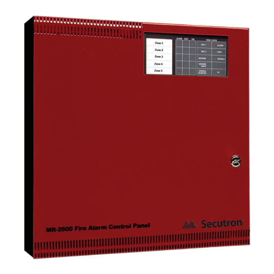
2.3 MR-2605 Overview FAULT Figure 1 MR-2605 cabinet with door closed Figure 2 MR-2605 display and controls Note: Use Security Screw provided to meet UL 864 Rev 9 requirement Figure 3 MR-2605 Cabinet Overview Secutron Inc. -
Page 16: Zone Label Insert
Using the charts in this manual, determine the wire gauge and wire run distances for the connected components. (initiating devices, indicating devices and ‘secur-bus’ connected components.) • Review the programming section of this manual and determine the operating characteristics required of the initiating zones, indicating zones and common panel features. Secutron Inc. -
Page 17: Electrical Specifications
Loop resistance: 100 ohms max. EOLR: 4.7 K ohm, ½ W, 5% Battery Charging Current 270mA maximum Low Battery Trouble Low Battery Trouble: 22.0 V Low Battery Trouble Restore: 23.0 VDC Critical Shutdown: 19±0.5 V Table 1 Electrical Specifications Secutron Inc. -
Page 18: Module Current Ratings
(mA) DC (mA) DC MR-2605 Control panel 475* MR-2605-T Remote trouble indicator MR-2605-AT R.T.I. and remote 5 zone annunciator MR-2806 DACT MR-2605-R3 Relay module** Table 2 Module Current Ratings Notes: *Current noted assumes ONE initiating zone is in alarm. The “Max. Alarm Current” assumes all zones are in alarm. - Page 19 13. Add the ‘standby’ Amp-Hr. to the ‘alarm’ Amp-Hr. for the total Amp-Hr. required. 14. Multiply the total Amp-Hr. times 1.20 for the minimum Amp-Hr. battery required to support the system for the selected ‘standby time and the selected ‘alarm’ time. Secutron Inc.
-
Page 20: Calculation For Standby Battery Requirement
2.7.1 Calculation for Standby Battery Requirement Step Device Current Number Total Total Alarm Standby Current device device Current (mA) (mA) (mA) MR-2605 Standby: = 130 Alarm: Zone 1 Standby: Alarm: Zone 2 Standby: Alarm: Zone 3 Standby: Alarm: Zone 4 Standby:... -
Page 21: Table 3 Battery Calculation Chart
Select a battery with an Amp-Hr. rating that is equal to or larger than the calculated minimum Amp-Hr. battery required. Note: The maximum battery allowed is 26 Ah. Install batteries outside the panel box. Total “Standby” current is not to exceed 0.5 Amperes. Secutron Inc. -
Page 22: Installing The Mr-2605 Fire Panel
Installing the MR-2605 Fire Panel 3.1 Environmental Specifications Consider the following conditions when selecting a mounting location for the MR-2605 panel: • Operating temperature: 32°F to 122°F / 0°C to 50°C • Humidity: 95% RH non-condensing • Close to a source of unswitched AC power... -
Page 23: Panel Assembly And Modules Locations
The panel comes completely assembled from the factory. Remove the lower dead front for access to the battery compartment. Remove display control panel for access to AC connections. Primary AC 240V 50Hz 120V 60Hz Figure 5 Panel Assembly and Modules Locations Secutron Inc. -
Page 24: Mounting The Mr-2605
3.3 Mounting the MR-2605 Dimensions in inches Figure 6 Mounting Dimensions Figure 7 Knockout Locations Secutron Inc. -
Page 25: Wiring The Mr-2605
Wiring the MR-2605 4.1 Wiring Specifications Figure 8 MR-2605 Terminals Descriptions Terminal Description Label NAC 1 Notification Appliance Circuit # 1 (+, –) 24 V , Full-Wave Rectified voltage, 1.5 Amps max. Programmable as Steady or Temporal output on alarm. -
Page 26: Table 4 Mr-2605 Terminal Descriptions
2-wire smoke detectors and initiating devices that employ dry contacts. (manual stations & heat detectors) Z2+…..Z5+ Same as zone 1 positive Z2-…..Z5- Same as zone 1 negative Table 4 MR-2605 Terminal Descriptions Note: For each supervised installation wire, a separate terminal must be used. Secutron Inc. -
Page 27: 2-Wire And 4-Wire Devices Typical Wiring
Type 1 - Smoke and contact devices instant alarm (default) Type 2 - Smoke auto-verify and contact as instant. Figure 10 Connecting 4-Wire Smoke Detectors • Program as zone type 01, instant alarm. • Maximum total loop wire resistance is 100 ohms. Secutron Inc. -
Page 28: Zone Wiring Chart
100 ohms. Maximum current 12,195 3,717 in alarm is 60 mA. 19,230 5,861 Table 5 Zone Wiring Chart 4.2 Connecting NAC Devices (Class ‘A’ and Class ‘B’) Figure 11 Connecting NAC Devices (Class ‘B’) Figure 12 Connecting NAC Devices (Class ‘A’) Secutron Inc. -
Page 29: Nac Wiring Chart
This chart is based on a minimum source voltage of 22 volts and a maximum line loss of 2 volts thus leaving a minimum of 20 volts at the last notification appliance. Table 6 NAC Wiring Chart Figure 13 Connecting Batteries Secutron Inc. -
Page 30: Figure 14 Connecting Ac Power
Connecting the Alarm and Trouble Relays Figure 16 Connecting Optional Devices See installation sheets for the remote devices for detailed wiring and address setup. • Maximum of 4 MR-2605-T per panel. • Maximum of 4 MR-2605-AT per panel. Secutron Inc. -
Page 31: Secur-Bus Wiring Chart
To calculate the wire run distance for any gauge wire and any maximum current value, use the following formula: Rmax = 1.25 ohms Imax Amps Distance = Rmax × 1,000 feet 2(wire resistance in ohms per 1,000 feet) Secutron Inc. -
Page 32: Table 8 Secur-Bus Devices
The following devices may be connected to the Secur-bus. All devices are supervised. See the section 6.3.7 Entering the Reset Programming Mode on page 48 for information on adding and deleting devices on the Secur-bus. Devices Description MR-2605-T External to control panel. Up to 4 of each device may be connected. MR-2605-AT MR-2806 Mounted inside control panel. -
Page 33: Panel Operation
This section describes how the panel functions under various conditions. The choices you make in panel programming will also affect how the panel operates. Please see Chapter 6 MR-2605 System Programming on page 39 for information on how to program the panel, and descriptions of each of the programming options. -
Page 34: Waterflow Alarms
If the Silence Trouble button is pressed, the buzzer turns off. Subsequent troubles will resound the trouble buzzer. Note: If there is no trouble present in the system then pressing the Silence Trouble button will result in a 1 second error tone. Secutron Inc. -
Page 35: System Troubles
Failure to communicate (Dialer) turns on sounds ½ deactivates second on/off Unsuccessful system reset turns on sounds ½ deactivates second on/off Loss of Dialer module turns on sounds ½ deactivates second on/off Table 9 System Faults and Troubles Secutron Inc. -
Page 36: System Reset Operation
1 second error tone. If any trouble or zone has a state change during lamp test, the lamp test will be cancelled and the panel will return to normal operation. Secutron Inc. -
Page 37: Walk Test (Installer Function Only)
Note: The Lamp Test button does not work while the panel is in Walk Test mode.Walk Test function not available without AC power. Secutron Inc. -
Page 38: Nac Operation
The panel deactivates the trouble relay upon any system trouble. The panel activates the trouble relay upon the restoral of all system troubles. 5.10.3 Supervisory Relay (available with the MR-2605-R3 Relay Expander only) The panel activates the supervisory relay upon any supervisory zone alarm. The panel deactivates the supervisory relay upon a successful system reset. -
Page 39: Mr-2605 System Programming
MR-2605 System Programming Programming the MR-2605 System is done using the Silence Trouble, Alarm Silence controls and the indicator LEDs. Programmed operating mode data is stored in non-volatile memory that retains the information if the power to the panel is removed. -
Page 40: Entering Installer Programming Mode
3. Press any button. The trouble buzzer is silent, and the zone 1 alarm LED turns on steady. The common trouble LED continues to flash. 4. The panel is now ready to program. Figure 17 Locating the Walk Test Switch Secutron Inc. -
Page 41: Using The Led Indicators To Program The System
6.3.7 Entering the Reset Programming Mode on page 48. Pressing the Lamp Test control enters the View Event Buffer mode. For more information see 6.4 Viewing the Event Buffer on page 51. Figure 19 Using the Controls to Program the System Secutron Inc. -
Page 42: Programming And Exiting The System
Press the Silence Trouble control to cycle through the Zones. To proceed to the next programming function cycle through all 5 zones. The Trouble LED flashes when the panel is in any Programming Mode. No other Panel Status LED’s will be lit. Secutron Inc. -
Page 43: Table 10 Led Indicators For Zone Programming
Not Used The zone is not used. The zone is not supervised, alarms and troubles are ignored. The end-of-line resistor is not required. Table 10 LED Indicators for Zone Programming Secutron Inc. -
Page 44: Nac Sounding Rate Programming
Temporal The NAC will sound the Temporal/ANSI Fire FAULT Pattern: 0.5 seconds ON, 0.5 seconds OFF, 0.5 seconds ON, 0.5 seconds OFF, 0.5 seconds ON, 1.5 seconds OFF, repeat. Table 11 LED Indicators for NAC Sounding Rate Programming Secutron Inc. -
Page 45: Nac Automatic Signal Silence And Nac2 Strobe Mode Programming
Only NAC2 can be set to this mode. Table 12 LED Indicators for NAC Auto SIlence and NAC2 Strobe Mode Programming Secutron Inc. -
Page 46: Signal Silence Inhibit Timer And Walk Test Programming
The bells pulse THREE times on any ground fault. Audible Walk Test - Silent Zone 2 The bells will not sound during the walk test. Audible Walk Test SILENT Table 13 LED Indicators for Signal Silence Inhibit Timer and Audible Walk Test Programming Secutron Inc. -
Page 47: Waterflow Alarms Programming
This applies to both automatic Alarm signal silence, and the Silence Alarm button. If DISABLED there is a trouble on a Waterflow zone following the alarm and alarm restore, the zone can be silenced. Table 14 LED Indicators for Waterflow Alarms Programming Secutron Inc. -
Page 48: Reference Ac Line Frequency (50 Or 60 Hz)
2. To enter the Reset Programming mode, press and hold the System Reset button for 2 seconds. The Zone1 Alarm LD and Trouble LED will be ON and all the System Trouble LEDs will flash Once in the Installer Programming Mode, the Reset Programming Mode can be accessed at any time. Secutron Inc. -
Page 49: Removing A Module From The System
Module FAULT Table 16 Removing an Module from the System 6.3.9 Adding a Module to the System Physically connecting the module to the system will allow the module to auto-enroll within one minute. No additional programming is required. Secutron Inc. -
Page 50: Defaulting The System
Please note that the ‘supervision’ field will be reset as well. Panel Status LED Alarm, Supervisory Programmable Setting Description Trouble LED’s Defaulting the System Zone 2 Defaulting the System FAULT Table 17 LED Indicators for Defaulting the System Secutron Inc. -
Page 51: Viewing The Event Buffer
9. Pressing the Silence Signal switch at any time will cause the system to exit the View Buffer mode. The buzzer will sound. Press any button to go to the Installer Programming Mode. Panel Status and Alarm, Supervisory and Trouble LEDs FAULT Figure 20 LED Indicators for Viewing the Event Buffer Secutron Inc. -
Page 52: Table 18 Event Buffer Table
Flashing AC On LED and Flashing BAT Warm Start TRB LED Flashing (ALL) Zone Trouble LED’s Walk Test Start / Installer Mode Entry Steady (ALL) Zone Trouble LED’s Walk Test End / Installer Mode Exit Table 18 Event Buffer Table Secutron Inc. -
Page 53: Startup Of The Mr-2605
Startup of the MR-2605 7.1 Prior to power up • Verify that all field wiring is free of shorts, opens and grounds and that end-of-line devices are connected and are the proper value. • Verify that all modules and internal cables are properly seated in their location. -
Page 54: Programming The Panel
Verify panel operations and feature selections by initiating alarms and troubles as described above. 7.5 Final Verification • Verify system operation and fault detection as required by the local Authority Having Jurisdiction. • Enable the ‘one-man’ walk test feature to test all the field devices and wiring. Secutron Inc. -
Page 55: Programming Worksheets
Programming Worksheets 8.1 Entering the Installer Programming Mode Please see Chapter 6 MR-2605 System Programming on page 39 for complete instructions. Note: All zone alarms must be reset prior to entering the Installer Programming Mode. While the panel is in the Installer Programming Mode, the annunciators will show a trouble condition. -
Page 56: Zone Programming
8.3 NAC Temporal/Steady Programming (Section 1) Please see 6.3.2 NAC Sounding Rate Programming on page 44. ZONE Programming Section Settings ALARM LED On NAC1 Temporal / Steady Temporal *Steady NAC2 Temporal / Steady Temporal *Steady * = Factory default Secutron Inc. -
Page 57: Nac Auto-Silence, Strobe Programming (Section 2)
* = Factory default 8.6 Waterflow Programming (Section 4) Please see 6.3.5 Waterflow Alarms Programming on page 47. ZONE Programming Section Settings ALARM LED On Waterflow Delay Timer Enabled *Disabled Silencing of Waterflow Alarms *Enabled Disabled * = Factory default Secutron Inc. -
Page 58: 50/60Hz Option (Section 5)
8.7 50/60Hz Option (Section 5) ZONE Programming Section Settings ALARM AC power 50Hz or 60Hz *60Hz 50Hz * = Factory default Secutron Inc. -
Page 59: Appendix: Uli Compatible Smoke Detectors
Thermal System Sensor 1100 Ionization, 2-wire, 12/ , terminal strip System Sensor 2100 Photoelectric, 2-wire, 12/24V , terminal strip System Sensor 2100T Photoelectric, 2-wire, 12/24V , thermistor, terminal strip System Sensor 2112/24T Photoelectric, 12/ , terminal strip Secutron Inc. -
Page 60: Table 19 Uli Compatible Smoke Detectors
2100S 2-wire direct wire Photoelectric System Sensor 2100TS 2-wire direct wire Photoelectric Thermal System Sensor 2100AT 2-wire direct wire Photoelectric Audible Thermal System Sensor 2100TR 2-wire direct wire Photoelectric Thermal Auxiliary Relay Table 19 ULI Compatible Smoke Detectors Secutron Inc. -
Page 61: Uli Compatible Smoke Detector Bases
DS284THSR DS284THCS Systems DS284THC DS284THE DS284ES DS284IS Gentex 8240 8240T 8240P 8243P 8240PH 8243PH 8240PT 8243PT Hochiki SIJ-24 SLR-24 SLR-24H SLR-835B MN240 MN240T MN240R MN240RT MN240S MN240ST MN240SR MN240SRT 741U 741UT Table 21 ULI Compatible 4-Wire Smoke Detectors Secutron Inc. -
Page 62: Uli Compatible Horns/Strobes
20-31 GES24-15 20-31 GES24-15/75 15/75 20-31 GES24-30 20-31 GES24-60 20-31 GES24-75 20-31 GES24-110 20-31 GEC24-15 20-31 GEC24-15/75 15/75 20-31 GEC24-30 20-31 GEC24-60 20-31 GEC24-75 20-31 GEC24-110 20-31 Available in Red and White. Table 23 ULI Compatible Gentex Horns/Strobes Secutron Inc. -
Page 63: Table 24 Uli Compatible Wheelock Horns/Strobes
20-31 AS-2475W-FR(W) 20-31 AS-24110W-FR(W) 20-31 AS4-2415C-FR(W) 20-31 AS4-2430C-FR(W) 20-31 AS4-2475C-FR(W) 20-31 AS4-24110C-FR(W) 20-31 AH-24-R 20-31 AH-24-WP-R 20-31 MT-24-R 20-31 MT4-24-R 20-31 MT-24-SL-VFR 20-31 MT-24-SLM-VFR 15/75 20-31 MT-24-MS-VFR 20-31 MT-24-IS-VFR 20-31 MT-24-WM-VFR 20-31 Table 24 ULI Compatible Wheelock Horns/Strobes Secutron Inc. -
Page 64: Fcc Compliance Statement
Consult the dealer or an experienced radio/television technician for help. The user may find the following booklet prepared by the FCC useful: “How to Identify and Resolve Radio/Television Interference Problems”. This booklet is available from the U.S. Government Printing Office, Washington D.C. 20402, Stock # 004-000-00345-4. Secutron Inc. -
Page 65: Warranty & Warning Information
Ambient conditions such as high humidity, high or low temperatures, or large temperature fluctuations may reduce the expected battery life. While each transmitting device has a low battery monitor which identifies when the batteries need to be replaced, this monitor Secutron Inc. - Page 66 Secutron shall not be liable for any delays, breakdowns, interruptions, loss, destruction, alteration or other problems in the use of a product arising our of, or caused by, the software.
-
Page 67: Limited Warranty
11.2 Limited Warranty Secutron Inc. warrants the original purchaser that for a period of three years from the date of shipment, the product shall be free of defects in materials and workmanship under normal use. -
Page 68: Conditions To Void Warranty
(including all implied warranties of merchantability or fitness for a particular purpose) And of all other obligations or liabilities on the part of Secutron Inc. neither assumes nor authorizes any other person purporting to act on its behalf to modify or to change this warranty, nor to assume for it any other warranty or liability concerning this product. -
Page 69: Out Of Warranty Repairs
Products which Secutron Inc. determines to be repairable will be repaired and returned. A set fee which Secutron Inc. has predetermined and which may be revised from time to time, will be charged for each unit repaired. - Page 70 Secutron Inc.
- Page 72 No part of this publication may be reproduced, transmitted, transcribed, stored in a retrieval system, or translated into any language or computer language, in any form by any means electronic, magnetic, optical, chemical, manual, or otherwise without the prior consent of Secutron. Canada U.S.A 25 Interchange Way...
Need help?
Do you have a question about the MR-2605 and is the answer not in the manual?
Questions and answers