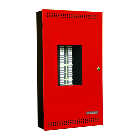
Secutron MR-2300 Series User Manual
Led fire alarm control panel
Hide thumbs
Also See for MR-2300 Series:
- Installation and operation manual (105 pages) ,
- Installation & operation manual (88 pages) ,
- User manual (20 pages)
Table of Contents
Advertisement
Quick Links
M R - 2 3 0 0 S E R I E S
LED Fire Alarm Control Panel
U
SER
G
UIDE
Revision A
Document #: LT-953SEC
WARNING: This manual contains information on limitations
regarding product use and function and information on the
limitations as to liability of the manufacturer. The entire
manual should be read carefully.
Advertisement
Table of Contents

Summary of Contents for Secutron MR-2300 Series
- Page 1 M R - 2 3 0 0 S E R I E S LED Fire Alarm Control Panel UIDE Revision A Document #: LT-953SEC WARNING: This manual contains information on limitations regarding product use and function and information on the limitations as to liability of the manufacturer.
- Page 2 Secutron Inc. Secutron Inc. 25 Interchange Way Vaughan, ON L4K 5W3 Please call us at 1-888-SECUTRON (1-888-732-8876) if problems arise with the installation or operation of these panels. For general product information, visit the Secutron web site: www.secutron.com.
-
Page 3: Cautions And Warnings
Cautions and Warnings READ AND SAVE THESE INSTRUCTIONS. Follow the instructions in this installation manual. These instructions must be followed to avoid damage to this product and associated equipment. Product operation and reliability depends upon proper installation. DO NOT INSTALL ANY PRODUCT THAT APPEARS DAMAGED. Upon unpacking your equipment, inspect the contents of the carton for shipping damage. -
Page 4: Table Of Contents
MR-2300 Series LED Version User Guide Contents Contents............................ i Introduction ..........................1 About this Manual ......................... 1 Technical SupportTechnical Support ..................1 Main Display ..........................2 The Buzzer and LED Indicators ....................3 Common LED Indicators....................... 3 Alarm Circuit Indicators......................5 Supervisory Circuit Indicators .................... -
Page 5: Introduction
Refer to the Glossary on page 9 for an explanation of commonly used terms in this manual. Technical Support For all technical support inquiries, please contact Secutron’s Technical Support Department between 8 A.M. and 5 P.M. (EDT) Monday through Friday, excluding holidays. -
Page 6: Main Display
Main Display Main Display Refer to the diagram below for the LED indicators and control buttons locations. WALK A.C. TEST REMOTE COMMON TROUBLE ALARM COMMON CPU FAIL SUPV GROUND COMMON FAULT TROUBLE BATTERY TROUBLE SIGNAL SYSTEM SILENCE RESET FIRE DISCONNECT DRILL LAMP TEST... -
Page 7: The Buzzer And Led Indicators
MR-2300 Series LED Version User Guide The Buzzer and LED Indicators Common LED Indicators Buzzer The buzzer sounds if there is a fire alarm, a supervisory alarm, or a trouble in the fire alarm system. It turns off if the condition causing the buzzer to sound goes away or if the Buzzer Silence Button is pressed. - Page 8 The Buzzer and LED Indicators General Alarm LED If the panel is configured as a two-stage system, the red General Alarm LED illuminates steadily GENERAL when the General Alarm button is pushed, a General Alarm Initiating circuit is activated, or the Auto ALARM General Alarm timer times out.
-
Page 9: Alarm Circuit Indicators
MR-2300 Series LED Version User Guide Alarm Circuit Indicators This operation applies to Initiating Circuits configured as Verified Alarm, Non-Verified Alarm, Water flow Alarm, Sprinkler Alarm, or General Alarm Circuits. The following table summarizes the indications at different events: Event... -
Page 10: Trouble-Only Circuit Indicators
The Buzzer and LED Indicators Trouble-only Circuit Indicators This operation applies to initiating circuits configured as Trouble-Only Circuits. The following table summarizes the indications in response to different events: Event Circuit Trouble LED Configuration Open circuit or (Style D)/(Class A) Flashes at the trouble rate trouble (amber) -
Page 11: Main Display Buttons
MR-2300 Series LED Version User Guide Main Display Buttons System Reset Button The System Reset button resets the fire alarm control panel and all circuits. SIGNAL SILENCE Signal Silence Button Pressing the Signal Silence button when the panel is in alarm deactivates any silenceable signal SIGNAL devices in the fire alarm system. -
Page 12: Circuit (Zone) Disconnect Buttons
Circuit (Zone) Disconnect Buttons Circuit (Zone) Disconnect Buttons Circuit (zone) disconnect buttons are provided for all initiating and indicating circuits on the fire alarm control panel. These buttons are located beside their respective indicating LEDs. Pressing a circuit disconnect button disconnects that circuit from the system and turns on its trouble indicator. While a circuit is disconnected, the panel will ignore all changes in the status (alarms and troubles) of that circuit. -
Page 13: Glossary
MR-2300 Series LED Version User Guide Glossary Alarm Occurs when devices such as detectors, pull stations, or sprinklers are activated. Condition In a single stage system, this condition will activate all signalling devices throughout the building. In a two stage system, this condition will activate an alert signal and the General Alarm timer. - Page 14 Glossary Supervisory Occurs when the system detects open circuits, short circuits, and grounds. A Condition supervisory condition is one that would interfere with the operation of the fire alarm system. Trouble Occurs when an abnormal condition such as a problem in the wiring, battery or Condition power circuits exists in the fire alarm system.
- Page 16 No part of this publication may be reproduced, transmitted, transcribed, stored in a retrieval system, or translated into any language or computer language, in any form by any means electronic, magnetic, optical, chemical, manual, or otherwise without the prior consent of Secutron. Canada U.S.A 25 Interchange Way...


Need help?
Do you have a question about the MR-2300 Series and is the answer not in the manual?
Questions and answers