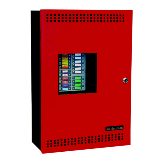
Secutron MR-2320 Series Installation And Operation Manual
Pre-action/deluge and agent release control panel
Hide thumbs
Also See for MR-2320 Series:
- Installation & operation manual (92 pages) ,
- Addendum for installation instructions (2 pages) ,
- Installation and operation manual (97 pages)
Table of Contents
Advertisement
Quick Links
Advertisement
Table of Contents

Related Manuals for Secutron MR-2320 Series


Summary of Contents for Secutron MR-2320 Series
- Page 1 MR-2320 Series Pre-Action/Deluge and Agent Release Control Panel FM APPLICATIONS MUST HAVE CLASS A INITIATING CIRCUITS ONLY (FOR RELEASING) AND 90 HOUR BATTERY STANDBY OPERATION LT-951SEC Rev. 5.3 Installation and Operation Manual November 2018...
-
Page 3: Table Of Contents
Table of Contents Introduction Panel Type ........................Overall Features ......................Conventions Circuits ........................... Zone ..........................Display Points ........................ Wiring Styles ........................System Components Main Pre-Action/Deluge and Agent Release Control Panel ........... Relay Modules: Six Relays .................... Polarity Reversal/City Tie ....................Smart Relay Module ...................... - Page 4 Table of Contents Indicating Circuit Wiring ....................Releasing Circuit Wiring ....................Four-Wire Smoke Detector Wiring ................. Relay Adder Module Wiring ................... Polarity Reversal and City Tie Module (MR-2300-PR) Wiring ........Power Supply Connection ....................Wiring Tables and Information ..................6.10 Four-Wire Smoke Power (regulated) ................
- Page 5 Table of Contents 10.2 General Panel Operation ....................11.0 Pre-Programmed Modes 11.1 Mode 1: Agent Release, Single Hazard, Cross-zoned, Combined Release ....11.2 Mode 2: Agent Release, Single Hazard, Not Cross-zoned, Combined Release ... 11.3 Mode 3: Agent Release, Dual Hazard, Cross-zoned, Split Release ......11.4 Mode 4: Agent Release, Dual Hazard, Not Cross-zoned, Split Release .......
- Page 6 List of Figures Figure 1 Box dimensions, semi-flush mounting and trim ring ............Figure 2 Installation of Adder Modules ..................Figure 3 Main Control Board cable connector and jumper settings ..........Figure 4 MR-2300-A Input Class-A Converter Adder Module ............. Figure 5 MR-2300-NC2 Output Class-A Converter Adder Module ..........
- Page 7 Indicating Circuit Wiring ....................Table 7 Relay Types ........................Table 8 Settings permitted in CAN/ULCS527 ................Table 9 Settings permitted in UL864 ................... Table 10 Access Levels ........................ Table 11 MR-2320 Series Specifications ..................Table 12 MR-2320 System Modules and Annunciators ..............
-
Page 8: Introduction
It supports auxiliary relays and a city tie module. The auxiliary relays are based on a hazard area status. The Secutron’s MR-2320 has six input zones and four output zones, allowing for flexibility in most single and dual-hazard applications for both deluge and agent releasing applications. - Page 9 Introduction • Configurable Signal Silence Inhibit and Auto Signal Silence Timers. For UL installations, disable the Auto Signal Silence Timer. • Subsequent Alarm, Supervisory, and Trouble operation. • Four wire reset-able smoke power supply. • Relay Contacts for Common Alarm, Common Supervisory, Common Trouble, and Auxiliary Alarm Relay (disconnectable).
-
Page 10: Conventions
Display Points There is a display point associated with every initiating and indicating circuit of the Secutron’s MR-2320 LED Series fire panel. For an initiating circuit there are two LEDs for every display point: one single color (amber) and one dual color (red/amber). For an indicating circuit there is only one LED: one single color (amber), for every display point. -
Page 11: System Components
System Components Main Pre-Action/Deluge and Agent Release Control Panel Model Description Six Zone Pre-Action/Deluge and Agent Release Control Panel with LED display, six Class B (Style B) initiating circuits, and four Class B (Style Y) output circuits. Output circuits 1 & 2 are Class B (Style B) indicating circuits that can be converted to Class A (Style Z) using an MR-2300-NC2 Output Class A... -
Page 12: Polarity Reversal/City Tie
System Components Polarity Reversal/City Tie Model Description Polarity Reversal and/ MR-2300-PR or City Tie Module Smart Relay Module Model Description Smart Relay Module (12 relays) MR-2312-SW12 with white enclosure MR-2300 SERIES REMOTE RELAY Input Class A Converter: Six Circuits Model Description Input Class A converter Module... -
Page 13: Output Class A Converter: Two Circuits
System Components Output Class A Converter: Two Circuits Model Description Output Class A converter MR-2300-NC2 module (two circuits) MR-2312-ATW Remote Annunciator Model Description A.C. COMMON SIGNAL TROUBLE SILENCE 16 Zone remote BUZZER SIGNAL MR-2312-ATW SILENCE SILENCE annunciator SWITCH ENABLE LAMP SYSTEM TEST RESET... -
Page 14: Mechanical Installation
National Electrical Code, ANSI/NFPA 70, and the National Fire Alarm Code ANSI/NFPA 72. Installing the Enclosure Install the MR-2320 Series panel enclosure as shown below. Mount enclosure surface mount using the four mounting holes with the provided screws. 11"... -
Page 15: Installing The Adder Modules
1” above the wall surface for proper door opening. Installing the Adder Modules The MR-2320 Series panel comes pre-assembled with all components and boards except for adder modules. Module installation locations are shown below. Refer to Figure 2 on the next page for Jumper or DIP Switch settings and see Wiring Tables and Information on page 30 for wiring specifications. -
Page 16: Figure 2 Installation Of Adder Modules
Mechanical Installation CLASS-A converter board for detection circuits MR-2300-A (6 circuits) IAC1 AC ON (ZONE 1) COMMON ALARM COMMON SUPV IAC2 (ZONE 2) COMMON TROUBLE BATTERY TROUBLE IAC3 REMOTE TROUBLE CLASS-A converter (ZONE 3) GROUND FAULT board for indicating IAC4 CPU FAIL circuits MR-2300-NC2 (ZONE 4) -
Page 17: Cable And Jumper Connections For Main Board, Core Board And Adder Modules
Cable and Jumper Connections for Main Board, Core Board and Adder Modules Main Pre-Action/Deluge and Agent Release Control Board JW4 -Factory Use Only Always Short JW5- Factory Use Only Always Open Main Board Core Board For front panel programming use CFG -300 configuration tool not UL-864 or ULC-S527 listed. -
Page 18: Mr-2300-A Input Class-A Converter Adder Module
Cable and Jumper Connections for Main Board, Core Board and Adder Modules Table 1 Connectors and Jumpers on the Main Fire Alarm Board Remove this jumper if MR-2300-PR is connected. Cable from connector P1 of the MR-2306-R6 Relay Adder Module connects here. Otherwise not used. -
Page 19: Mr-2300-Nc2 Output Class-A Converter Adder Module
Cable and Jumper Connections for Main Board, Core Board and Adder Modules positive and negative terminals marked DET OUT and the circuit return wires are brought back to the converter module to positive and negative terminals marked DET RET. MR-2300-NC2 Output Class-A Converter Adder Module mounting hole for #6-32 screws OCAC-302... -
Page 20: Polarity Reversal And City Tie Module (Model Mr-2300-Pr)
Cable and Jumper Connections for Main Board, Core Board and Adder Modules The correlation of the relays are fixed and is as follows: Relay1 Relay2 Relay3 Relay4 Relay5 Relay6 Hazard 1 Hazard 1 Hazard 1 Hazard 2 Hazard 2 Hazard 2 Active State Alert Alarm... -
Page 21: Field Wiring
Field Wiring Table 4 Settings permitted in CAN/ULCS527 NOTICE TO USERS, INSTALLERS, AUTHORITIES HAVING JURISDICTION, AND OTHER INVOLVED PARTIES This product incorporates field-programmable software. In order for the product to comply with the requirements in CAN/ULCS527, Standard for Control Units for Fire Alarm Systems, certain programming features or options must be limited to specific values or not used at all as indicated below. -
Page 22: Figure 8 Initiating Circuit - Class B Or Style B Wiring
Field Wiring 6.1.1 Initiating Circuit Wiring Wiring diagrams for the initiating circuits are shown below. The panel supports Style B wiring for the initiating circuits and Style D wiring for the indicating circuits. The initiating circuits are supervised by a 3.9KΩ EOL resistor or an active EOL module. STYLE B WIRING FIRE ALARM MAIN BOARD... -
Page 23: Abort And Manual Release Switch Wiring
Field Wiring Abort and Manual Release Switch Wiring Wiring for the abort and manual release switches is shown in Figures 10 and 11. The Abort and Manual release switches must be on different circuits. DET5 is used for the Abort switch and DET6 is used for the manual release switch. -
Page 24: Figure 11 Abort And Manual Release Switch Class A Or Style D Wiring
Field Wiring FM APPLICATIONS MUST HAVE CLASS A INITIATING CIRCUITS ONLY (FOR RELEASING) AND 90 HOUR BATTERY STANDBY OPERATION Abort and Manual Release switches on separate circuits ICAC-306 CLASS A FIRE ALARM MAIN BOARD CONVERTER MODULE INITIATING CIRCUIT #5 INITIATING CIRCUIT #6 Manual Release switches on separate circuits ICAC-306... -
Page 25: Indicating Circuit Wiring
Field Wiring Indicating Circuit Wiring The MR-2320 Series Fire Alarm supports Class B or Style Y and Class A Style Z wiring for its indicating circuits. Each circuit is supervised by a 3.9KΩ EOL resistor or active EOL module. Each indicating circuit provides up to 1.7 A, 5 A maximum total if no auxiliaries are used. -
Page 26: Releasing Circuit Wiring
Field Wiring Releasing Circuit Wiring Wiring for the releasing circuit is shown in Figure 14 below. SIG3 and SIG4 output circuits are reserved for the releasing circuits. Solenoid EOL module (MP-320R/W) is used to supervise the solenoid coil. If the solenoid is already fitted with the directional diode then only the 3.9KΩ EOL resistor is used. -
Page 27: Four-Wire Smoke Detector Wiring
Field Wiring Four-Wire Smoke Detector Wiring FIRE ALARM MAIN BOARD POWER RESETTABLE 4-WIRE SMOKE DETECTOR POWER SUPPLY 22VDC, 200mA MAX. CURRENT - 300mA MAX. RIPPLE VOL. 5mV (POWER LIMITED) DETECTION END OF LINE RELAY 4-WIRE DETECTION DEVICE LISTED S3403 MODEL A77-716B TO INITIATING MANUFACTURED BY CIRCUIT... -
Page 28: Polarity Reversal And City Tie Module (Mr-2300-Pr) Wiring
Field Wiring Polarity Reversal and City Tie Module (MR-2300-PR) Wiring Wire MR-2300-PR Polarity Reversal and City Tie Module (if used) as shown in Figure 17 below. See Appendix C: Specifications on page 84 for module specifications. Power Limited cable type FPL, FPLR or FPLP must be used. For USA installation, the installer must use Atlantic Scientific (Tel: 407-725-8000), Model #24544 Protective Device, or similar UL-Listed QVRG secondary protector, as shown. -
Page 29: Power Supply Connection
Field Wiring Power Supply Connection The power supply is part of the Main Chassis. The ratings are: Type Rating 120 VAC 60Hz 1.75 A / 240 VAC 50 Hz 0.93 A, 10A Electrical Input rating slow blow fuse on secondary of transformer Power supply total current 6.5A AC maximum @ secondary of transformer Battery fuse on Main... -
Page 30: Wiring Tables And Information
Field Wiring Wiring Tables and Information Table 5 Initiating Circuit Wiring Wire gauge Maximum wiring run to last device Feet Meters 2990 4760 1450 7560 2300 12000 3600 19000 5800 30400 9200 Note: For Class A the maximum wiring run to the last device is divided by two. Maximum loop resistance should not exceed 100 ohms. -
Page 31: Supervised Auxiliary Power (Regulated)
Field Wiring 6.11 Supervised Auxiliary Power (regulated) Supervised auxiliary power is used to power the remote annunciators and smart relay modules. This filtered circuit is supervised therefore a short will disconnect the power and the common trouble is active. The power is reconnected after the 'RESET' key is pressed. See Appendix C: Specifications on page 84 for supply rating. -
Page 32: System Checkout
System Checkout Before turning the power “ON” 1. To prevent sparking, do not connect the batteries. Connect the batteries after powering the system from the main AC supply. 2. Check that all modules are installed in the proper location with the proper connections. 3. - Page 33 System Checkout Remote Trouble will be indicated on the main panel display for any failure Remote reported by, or failure to communicate with a remote annunciator or other Trouble remote device. This panel has a common ground fault detector. To correct the fault, Ground Fault check for any external wiring touching the chassis or other Earth Ground connection.
-
Page 34: Indicators, Controls And Operations
Indicators, Controls and Operations Refer to Figure 19 below for LED Indicator and Control Button locations. IAC1 AC ON (ZONE 1) COMMON ALARM COMMON SUPV IAC2 (ZONE 2) COMMON TROUBLE BATTERY TROUBLE IAC3 REMOTE TROUBLE (ZONE 3) GROUND FAULT IAC4 CPU FAIL (ZONE 4) ABORT... -
Page 35: Common Led Indicators
Indicators, Controls and Operations Note: Note that each display is supplied with laser printer printable paper labels for sliding into the plastic label template on the panel. For the Main Display, the paper label is part number NP-2056; this includes English and French versions. Common LED indicators 8.1.1 AC ON... -
Page 36: Menu Buttons
To return to previous menu in the configuration or command mode. Button Switches and Common Indicators The MR-2320 Series panel is a six-zone panel with four output circuits. The circuits are arranged in the following configuration: Zone 1 Input circuit... -
Page 37: Common Controls
Indicators, Controls and Operations Out 1 NAC1 Out 2 NAC2 Out 3 Releasing circuit 1 Out 4 Releasing circuit 2 or NAC3 in some applications 8.3.1 Zone 1 to Zone 4 • Alarm LED (red) turns on steady when an alarm is detected •... -
Page 38: Circuit (Zone) Disconnect Buttons
Indicators, Controls and Operations • Stops and resets all Timers • Processes inputs as new events • Does not affect Aux Disconnect 8.4.2 Signal Silence Button Activation of the Signal Silence button when the panel is in alarm turns on the Signal Silence indicator and deactivates any Silenceable Indicating Circuits. -
Page 39: Common Relays
Indicators, Controls and Operations When an Initiating Circuit Disconnect pushbutton is returned to the normal state (by pressing it again in order to un-bypass the circuit), the panel checks the state of the circuit. If the circuit is active, the Status Indicator flashes for 10 seconds at the Fast Rate without processing the input. - Page 40 Indicators, Controls and Operations 8.7.4 Non-Latching Supervisory (For Supervisory Circuits) Activation on these circuits will cause the Circuit Status LED and the amber Common Supervisory LED to illuminate. The buzzer will sound at fast rate. If the circuit activation is removed, the Supervisory condition will clear (as long as there are no other Supervisory conditions in the system) and the Circuit Status LED will turn off.
-
Page 41: Evacuation Codes
Indicators, Controls and Operations Evacuation codes Continuous On 100% of the time Temporal Code 3 of 0.5 second on, 0.5 second off then, 1.5 second pause 20 BPM 1.5 seconds on, 1.5 seconds off 60 BPM 0.5 second on, 0.5 second off 120 BPM 0.25 second on, 0.25 second off CONTINUOUS... -
Page 42: Configuration
Modes 1, 2, 5, 6, 7, 8, release on same circuit 10, 11, 12, 13, 14 9, 10, 11, 12, 13, 14 (unsupervised) Configure the MR-2320 Series Panels using the CFG-300 LCD Tool (see further documentation packaged with CFG-300 for configuration information). -
Page 43: Using The Cfg-300 Tool
Configuration Using the CFG-300 Tool Connect the CFG-300 to the panel, then press (Menu button). The CFG-300 LCD display will display the Main Menu. The function of different buttons on the front panel display is shown in Figure 21 below. This label removed from this location... -
Page 44: Entering The Passcode
Configuration Entering the Passcode The programming section is passcode protected. The following screen shows the message that is displayed to enter the passcode. The maximum allowable passcode is ten digits long, and permits numerical values only. Press (Enter button) after entering the passcode. If the passcode is correct, it will take you to the main command menu. -
Page 45: Command Menu
Configuration Command Menu The main command menu is pictured below. The first line of the LCD will always show “- Command Menu-“, and the second line scrolls through different selections. Use the “UP” and “DOWN” keys to scroll through the menu, and press the key to make a selection. -
Page 46: Panel Config (Command-Menu)
Configuration 1. Panel Config (Command-Menu) The following is a detailed description of the MR-2320 configuration menu. Note: Refer to How to Use the Keypad to Program the MR-2320 on page 44 for detailed instructions on making menu selections. -Panel Config- 1. - Page 47 Configuration Command Menu-->Panel Config--> Use this function to set the Hazard Config programmable timer that delays the activation of the releasing application circuits. 1. Release Timer This timer starts immediately 60->Default after receiving a confirming Release timer(sec): Available options: alarm (cross-zoned hazard 0,5,10,15,20,25,30,35,40, area) or a single alarm (non- 45,50,55,60 seconds...
- Page 48 Configuration Command Menu-->Panel Config-->Features -Panel Features- 1. Man. Sig. Sil 2. Wtr/Sprk. Retd 3. Aux Dis Corr 4. Sig-Sil Inh Tm 5. Aux Dis Alm&Sv 6. Auto Sil. Tmr 7. Rem. Annun. 8. Alm. Xmit. Sil. 9. Pwr Fail Tmr. 10.
- Page 49 Configuration By default this function will Command Menu-->Panel Config-->Features disconnect the auxiliary alarm relay when the aux disconnect 3. Aux Dis Corr button is pressed. If enabled, this function will disconnect Aux Dis. Dis Corr [X] ENABLE ->Default the auxiliary alarm relay and [ ] DISABLE all correlated relays when the [X] ENABLE...
- Page 50 Configuration Command Menu-->Panel Config-->Features Use this function to delay the reporting of AC power fail 9. Pwr Fail Tmr [X] NONE->Default trouble for a specific time [ ] 1 HRS period. If disabled, the AC AC Pwr Fail Dly Tmr. [ ] 3 HRS power fail will be reported [X] None...
- Page 51 Configuration Command Menu-->Panel Config-->Features 16. Sig-Sil NAC Use this function to set which [X] NAC-1->Default NAC circuits are silenceable or Silenceable NAC [X] NAC-2->Default non-silenceable. [X] NAC-1 Command Menu/MR-2320 Config/Features/ Enable this function if using an Active EOL. If MR-2300-A is 17.
-
Page 52: Set Time (Command-Menu)
Configuration 2. Set Time (Command-Menu) Note: Refer to How to Use the Keypad to Program the MR-2320 on page 44 for detailed instructions on making menu selections. 1. Daylight Save 2. Time Clock 3. Compensation Command Menu/Set time Date 1. Daylight saving time Use this function to enable [X] DISABLE ->Default... -
Page 53: Set Password (Command-Menu)
Configuration 3. Set password (Command-Menu) Note: Refer to How to Use the Keypad to Program the MR-2320 on page 44 for detailed instructions on making menu selections. First choose the level of password to be changed Select Access Level Then Enter new passcode: Re-enter new passcode: Use this function to change... -
Page 54: View Event Log (Command-Menu)
Configuration 4. View Event Log (Command-Menu) The event log looks the same as the normal event queue. Pressing the “INFO” key has the same effect that it does in the event queue. The illustration below provides an example of how the “INFO”... -
Page 55: Clear Event Log (Command-Menu)
Configuration 9.10 6. Clear Event Log (Command-Menu) Note: Refer to How to Use the Keypad to Program the MR-2320 on page 44 for detailed instructions on making menu selections. -Select Log- 1. Alarm Log 2. General Log 3. All Logs Select the type of log to clear. -
Page 56: Operating The Panel
10.0 Operating the Panel 10.1 Panel Operation During Various Hazard States The escalating hazard zone states include Idle, Alert, Alarm and Release. They are defined based on the status of Hazard Area input zone(s), correlated Abort Switch and Manual Release Switch. 10.1.1 Hazard Idle •... -
Page 57: General Panel Operation
Operating the Panel released, the hazard state will go back to Hazard Alarm and the Release Timer resumes running. The value of release timer depends on Abort Delay Type. The corresponding NAC sounds Alarm rate again. 10.1.4 Hazard Release • Panel enters Hazard Release when the Release Timer or Manual Release Timer expires. -
Page 58: Pre-Programmed Modes
11.0 Pre-Programmed Modes 11.1 Mode 1: Agent Release, Single Hazard, Cross-zoned, Combined Release Detection Zones Phantom Zones Release Timers Z1+Z2 Z3+Z4 Out1 Signal Steady Out2 Signal Escalating Out3 Rel. Releasing Out4 Rel. Releasing RLS TMR 1 Started RLS Tmr 1 Interrupted RLS Tmr 1 Cancelled RLS Tmr 2 Started RLS Tmr 2 Interrupted... - Page 59 Pre-Programmed Modes 11.1.3 NAC Configuration • Default Escalating NAC code of Hazard Area State: • Hazard Idle: Off • Hazard Alert: Temporal (see Table 8) • Hazard Alarm: 120 BPM • Hazard Release: Steady • Default NAC code of Supervisory is 20 BPM. 11.1.4 How the Panel Works in Mode 1 •...
-
Page 60: Mode 2: Agent Release, Single Hazard, Not Cross-Zoned, Combined Release
Pre-Programmed Modes 11.2 Mode 2: Agent Release, Single Hazard, Not Cross-zoned, Combined Release Detection Zones Phantom Zones Release Timers Z1+Z2 Z3+Z4 Out1 Signal Steady Out2 Signal Escalating Out3 Rel. Releasing Out4 Rel. Releasing RLS TMR 1 Started RLS Tmr 1 Interrupted RLS Tmr 1 Cancelled RLS Tmr 2 Started RLS Tmr 2 Interrupted... -
Page 61: Mode 3: Agent Release, Dual Hazard, Cross-Zoned, Split Release
Pre-Programmed Modes 11.2.4 How the Panel Works in Mode 2 • Activation of either Z-1 or Z-2 turns NAC-1 on steady. • Activation of either Z-1 or Z-2 changes the Hazard Area 1 state from Idle into Alarm directly. NAC-1 turns on steady. NAC-2 turns on Temporal. Release Timer-1 is started. •... -
Page 62: Mode 5: Pre-Action/Deluge, Single Hazard, Cross-Zoned, Combined Release
Pre-Programmed Modes 11.5 Mode 5: Pre-action/Deluge, Single Hazard, Cross-zoned, Combined Release Detection Zones Phantom Zones RT1 Exp Supv Z1+Z2+Z3+Z4 Out1 Signal Steady Out2 Signal Escalating Out3 Rel. Releasing Out4 Rel. Releasing RLS TMR 1 Started RLS Tmr 1 Interrupted RLS Tmr 1 Cancelled 11.5.1 Zone Configuration •... - Page 63 Pre-Programmed Modes • Activations of any two of Z-1, Z-2, Z-3 and Z-4 change Hazard Area 1 state into Alarm. Release Timer-1 is started. NAC-2 turns on at 120 BPM. Upon the expiration of Release Timer 1, both RAC-1 and RAC-2 turn on. NAC-1 and NAC-2 turn on Steady •...
-
Page 64: Mode 6: Pre-Action/Deluge, Single Hazard, Not Cross-Zoned, Combined Release
Pre-Programmed Modes 11.6 Mode 6: Pre-action/Deluge, Single Hazard, Not Cross-zoned, Combined Release Detection Zones Phantom Zones RT1 Exp Supv Z1+Z2+Z3+Z4 Out1 Signal Steady Out2 Signal Escalating Out3 Rel. Releasing Out4 Rel. Releasing RLS TMR 1 Started RLS Tmr 1 Interrupted RLS Tmr 1 Cancelled 11.6.1 Zone Configuration •... - Page 65 Pre-Programmed Modes 11.6.4 How the Panel Works in Mode 6 • Activation of any one among Z-1, Z-2, Z-3 and Z-4 changes Hazard Area 1 state into Alarm. Release Timer-1 is started. NAC-1 turns on at Temporal. Upon the expiration of Release Timer-1, NAC-1 turns on steady.
-
Page 66: Mode 7: Pre-Action/Deluge, Dual Hazard, Cross-Zoned, Split Release
Pre-Programmed Modes 11.7 Mode 7: Pre-action/Deluge, Dual Hazard, Cross-zoned, Split Release Detection Zones Phantom Zones Release Timers Supv Z1+Z2 Z3+Z4 Out1 Signal Steady Out2 Signal Escalating Out3 Rel. Releasing Out4 Rel. Releasing RLS TMR 1 Started RLS Tmr 1 Interrupted RLS Tmr 1 Cancelled RLS Tmr 2 Started RLS Tmr 2 Interrupted... - Page 67 Pre-Programmed Modes 11.7.4 How the Panel Works in Mode 7 • Activation of either Z-1 or Z-2 changes Hazard Area 1 state into Alert. NAC-1 turns on at Temporal. • Activations of both Z-1 and Z-2 change Hazard Area 1 state into Alarm. Release Timer- 1 is started.
-
Page 68: Mode 8: Pre-Action/Deluge, Dual Hazard, Not Cross-Zoned, Split Release
Pre-Programmed Modes 11.8 Mode 8: Pre-action/Deluge, Dual Hazard, Not Cross-zoned, Split Release Detection Zones Phantom Zones Release Timers Supv Z1+Z2 Z3+Z4 Out1 Signal Steady Out2 Signal Escalating Out3 Rel. Releasing Out4 Rel. Releasing RLS TMR 1 Started RLS Tmr 1 Interrupted RLS Tmr 1 Cancelled RLS Tmr 2 Started RLS Tmr 2 Interrupted... - Page 69 Pre-Programmed Modes 11.8.4 How the Panel Works in Mode 8 • Activation of either Z-1 or Z-2 changes Hazard Area 1 state into Alarm. Release Timer 1 is started. NAC-1 turns on at Temporal. Upon the expiration of Release Timer 1, RAC-1 is active.
-
Page 70: Mode 9: Agent Release, Single Hazard, Cross-Zoned, Nyc Abort
Pre-Programmed Modes 11.9 Mode 9: Agent Release, Single Hazard, Cross-zoned, NYC abort Detection Zones Phantom Zones Release Timers Supv Z1+Z2 Z3+Z4 Out1 Signal Steady Out2 Signal Escalating Out3 Rel. Releasing Out4 Strobe Steady RLS TMR 1 Started RLS Tmr 1 Interrupted RLS Tmr 1 Cancelled RLS Tmr 2 Started RLS Tmr 2 Interrupted... - Page 71 Pre-Programmed Modes • Default NAC code of supervisory is 20 BPM 11.9.4 How the Panel Works in Mode 9 • The activation of either Z-1 or Z-2 turns NAC-1 on steady. • The activations of both Z-1 and Z-2 turn NAC-1 off, turn NAC-2 on at 120BPM, and turn NAC-3 on steady.
-
Page 72: Mode 10: Agent Release, Single Hazard, Not Cross-Zoned, Combined Release
Pre-Programmed Modes 11.10 Mode 10: Agent Release, Single Hazard, Not Cross-zoned, Combined Release Detection Zones Phantom Zones Release Timers Supv Z1+Z2 Z3+Z4 Out1 Signal Steady Out2 Signal Escalating Out3 Rel. Releasing Out4 Rel. Releasing RLS TMR 1 Started RLS Tmr 1 Interrupted RLS Tmr 1 Cancelled RLS Tmr 2 Started RLS Tmr 2 Interrupted... - Page 73 Pre-Programmed Modes • Default NAC code of supervisory is Temporal (see Table 8) 11.10.4 How the Panel Works in Mode 10 • Activation of either Z-1 or Z-2 turns NAC-1 on steady. • Activation of either Z-1 or Z-2 turns NAC-2 on at 60BPM. Release Timer-1 is started. •...
-
Page 74: Mode 11: Agent Release, Single Hazard, Cross-Zoned, Combined Release
Pre-Programmed Modes 11.11 Mode 11: Agent Release, Single Hazard, Cross-zoned, Combined Release Detection Zones Phantom Zones Release Timers Supv Z1+Z2 Z3+Z4 Out1 Signal Steady Out2 Signal Escalating Out3 Rel. Releasing Out4 Rel. Releasing RLS TMR 1 Started RLS Tmr 1 Interrupted RLS Tmr 1 Cancelled RLS Tmr 2 Started RLS Tmr 2 Interrupted... - Page 75 Pre-Programmed Modes • Default NAC code of supervisory is 20 BPM 11.11.4 How the Panel Works in Mode 11 • The activation of either Z-1 or Z-2 turns NAC-1 on steady. • The activations of both Z-1 and Z-2 turn NAC-1 off and turn NAC-2 on at 60BPM. Release Timer-1 is started.
-
Page 76: Mode 12: Pre-Action/Deluge, Single Hazard, Cross Zoned, Combined Release
Pre-Programmed Modes 11.12 Mode 12: Pre-action/Deluge, Single Hazard, Cross Zoned, Combined Release Attention: This mode of operation is not FM approved. Detection Zones Phantom Zones Supv Supv Z1+Z2+Z3 Out1 Signal Steady Out2 Signal Escalating Out3 Rel. Releasing Out4 Rel. Releasing RLS TMR 1 Started RLS Tmr 1 Interrupted RLS Tmr 1 Cancelled... - Page 77 Pre-Programmed Modes • Hazard Release: Steady • Default NAC code of Supervisory is 20 BPM. 11.12.4 How the Panel Works in Mode 12 • Activation of Z-1, Z-2 or Z-3 changes Hazard Area 1 state from Idle to Alert. NAC-1 turns on steady.
-
Page 78: Mode 13: Pre-Action/Deluge, Single Hazard, Not Cross Zoned, Combined Release
Pre-Programmed Modes 11.13 Mode 13: Pre-action/deluge, Single Hazard, Not Cross Zoned, Combined Release Detection Zones Phantom Zones Supv Supv Z1+Z2+Z3 Out1 Signal Steady Out2 Signal Escalating Out3 Rel. Releasing Out4 Rel. Releasing RLS TMR 1 Started RLS Tmr 1 Interrupted RLS Tmr 1 Cancelled 11.13.1 Zone Configuration •... - Page 79 Pre-Programmed Modes 11.13.4 How the Panel Works in Mode 13 • Activation of any one among Z-1, Z-2 or Z-3 changes Hazard Area 1 state into Alarm. Release Timer-1 is started. NAC-1 turns on at Temporal. Upon the expiration of Release Timer-1, NAC-1 turns on steady.
-
Page 80: Mode 14: Pre-Action/Deluge, Single Hazard, Not Cross Zoned, Combined Release
Pre-Programmed Modes 11.14 Mode 14: Pre-action/deluge, Single Hazard, Not Cross Zoned, Combined Release Attention: This mode of operation is neither FM nor UL approved. Detection Zones Phantom Zones Supv Z1+Z2+Z3 Out1 Signal Steady Out2 Signal Escalating Out3 Rel. Releasing Out4 Rel. - Page 81 Pre-Programmed Modes • Hazard Release: Steady • Default NAC code of Supervisory is 20 BPM. 11.14.4 How the Panel Works in Mode 14 • Activation of any one among Z-1, Z-2, Z-3 or Z4 changes Hazard Area 1 state into Alarm.
-
Page 82: Appendix A: Compatible Solenoids
12.0 Appendix A: Compatible Solenoids Manufacturer Description ASCO 8210 series T8210A107 24VDC R8210A107 24VDC 8210A107 24VDC AMEREX 17014 Actuator BSCO 510006 Actuator Kidde Fenwal Protection Systems 486500-01 Actuator Parker 73212 Valve Solenoid Parker Skinner Valve Division Cardox 7-061-0006 V5L 72750 Valve Solenoid SIEMENS CPYEC-2-24... -
Page 83: Appendix B: Compatible Synchronized Modules And Horn/Strobes (Ul/Ulc)
Manufacturer Brand Sync. Module Horns/Strobes Maximum # of Horns/Strobes Cooper NS-24MCW-FW/-FR Cooper Wheelock DSM-12-24 Wheelock Horn/Strobes Gentex Secutron AVS44-R MRA-HS3-24 Horn/Strobe SpectrAlert System Sensor P1224 MC Horn/Strobe Amseco/Potter Mircom SDM-240 FHS-240-110 Horn/Strobe ZR-MC-R/-W, ST-MC-R-AR, MTH-MC Strobes Faraday... -
Page 84: Appendix C: Specifications
14.0 Appendix C: Specifications Table 11 MR-2320 Series Specifications MR-2320 Series Fire Control Panel Chassis General Digital Signal Processor (DSP) based design. Fully configurable using front panel LCD display with Password Access. Indicating (NAC) 2 supervised style Y (Class B) indicating circuits, configured as strobes or Circuits audibles. -
Page 85: Table 12 Mr-2320 System Modules And Annunciators
10A on board (F1) slow blow micro fuse Ground Fault Circuit Less than 3.3 kΩ will generate a ground fault. Compliance System Model MR-2320 Series Control Unit - Fire Alarm, for Releasing services System Type Local Auxiliary (using MR-2300-PR) Type of Service... - Page 86 Appendix C: Specifications Table 12 MR-2320 System Modules and Annunciators (Continued) MR-2320 System Modules and Annunciators MR-2312-S12 Must be connected to a listed power-limited source of supply Smart Relay Contact rating FormC/ 28VDC per contact / 1A resistive load max, zoned Module Current consumption standby 30mA / alarm 140mA MR-2306-ATW...
-
Page 87: Appendix D: Power Supply And Battery Calculations (Selection Guide)
Battery (AH) = ([STANDBY (A) ______ ] x [(24,60 or 90 Hours) ___ ]) + ([ALARM (B) ______ ] x [Alarm in Hr.] _____) = (C) ______AH Total System Current in Alarm State: Must be 5.5 amperes or less for MR-2320 Series. Battery Selection: Multiply (C) by 1.20 to derate battery. -
Page 88: Warranty And Warning Information
Please read this document CAREFULLY, as it contains important warnings, life-safety, and practical information about all products manufactured by the Mircom Group of Companies, including Mircom and Secutron branded products, which shall include without limitation all fire alarm, nurse call, building automation and access control and card access products (hereinafter individually or collectively, as applicable, referred to as “Mircom System”). - Page 89 Warranty and Warning Information The testing should include all sensing devices, keypads, consoles, alarm indicating devices and any other operational devices that are part of the system. NOTE TO USERS: All Mircom Systems have been carefully designed to be as effective as possible. However, there are circumstances where they may not provide protection.
- Page 90 Warranty and Warning Information 13. Wireless Devices Placement Proximity. Moreover all wireless devices must be a minimum and maximum distance away from large metal objects, such as refrigerators. You are required to consult the specific Mircom System manual and application guide for any maximum distances required between devices and suggested placement of wireless devices for optimal functioning.
- Page 91 Warranty and Warning Information...
- Page 92 U.S.A CANADA - Main Office © Secutron 2018 25 Interchange Way 4575 Witmer Industrial Estates Printed in Canada Subject to change without prior notice Niagara Falls, NY 14305 Vaughan, ON L4K 5W3 Tel: (888) 660-4655 Tel: (888) 660-4655 www.secutron.com...
Need help?
Do you have a question about the MR-2320 Series and is the answer not in the manual?
Questions and answers
are there recommended maintenance procedures to follow
Recommended maintenance procedures for the Secutron MR-2320 Series include:
1. Ensure all interconnection cables are secure and connectors are properly plugged in.
2. Verify all jumpers and switches are correctly set.
3. Check AC power wiring for proper connection.
4. Ensure the chassis is connected to Earth Ground (cold water pipe).
5. Close the front cover plate before powering the system.
6. For initial power-up, do not connect field wiring. Power the panel with an end-of-line resistor and check for trouble conditions.
7. After confirming the panel is trouble-free, connect one circuit at a time, correcting any faults before continuing.
Repairs or alterations should only be made by an authorized Canadian maintenance facility designated by the supplier.
This answer is automatically generated