
Subscribe to Our Youtube Channel
Related Manuals for Secutron MR-3318


Summary of Contents for Secutron MR-3318
- Page 1 MR-3318 Fire Alarm Control Panel LT-1202SEC Rev 0 Installation and Operation Manual 2018...
-
Page 3: Table Of Contents
Table of Contents FCC Notice Notice for all MR-3318 Series Built-in UDACTs Sold in the U.S.A......... FCC Notice ........................Introduction The MR-3318 Addressable Fire Alarm Control Panel ............ General Notes ........................ MR-3318 Overview MR-3318 Fire Alarm Control Panel Model .............. - Page 4 11.0 Appendix D - Reporting 11.1 Ademco Contact-ID MR-3318 Series Event Codes ............11.2 Security Industries Association SIA Format Protocol MR-3318 Series Event Codes ..12.0 Appendix E - Specifications And Features 12.1 MR-3318 Fire Alarm Control Panel ................12.2 MR-3318 System Module and Annunciator Specifications ..........
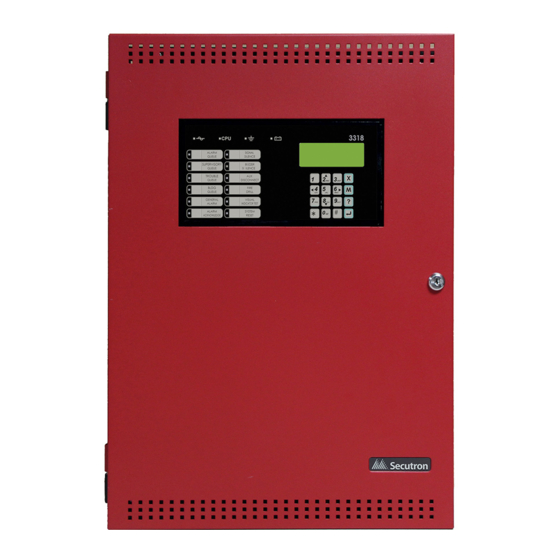
- Page 5 List of Figures Figure 1 Model MR-3318 Single Loop Fire Alarm Control Panel ..........Figure 2 MR-3318 Mechanical Installation Instructions and Dimensions ........Figure 3 Main Board with all Modules Installed ................Figure 4 Port and Jumper Locations on Main Board ..............
- Page 6 Compatible DACR Receivers ..................Table 23 MR-3318 Compatible Horn/Strobes ................Table 24 Contact-ID Event Codes ....................Table 25 SIA-DCS Event Codes ....................Table 26 MR-3318 Specifications ....................Table 27 MR-3318 System Modules and Annunciator Specifications .......... Table 28 Recommended Batteries ....................
-
Page 7: Fcc Notice
Attention: Users should not attempt to make such connections themselves, but should contact the appropriate electric inspection authority, or electrician, as appropriate. Notice for all MR-3318 Series Built-in UDACTs Sold in the U.S.A. Notes: The Ringer Equivalence Number (REN) assigned to each terminal device provides an indication of the maximum number of terminals allowed to be connected to a telephone interface. - Page 8 operations or procedures. If these changes might affect your service or the operation of your equipment, the telephone company will give you notice, in writing, to allow you to make any changes necessary to maintain uninterrupted service. In certain circumstances, it may be necessary for the telephone company to request information from you concerning the equipment which you have connected to your telephone line.
-
Page 9: Introduction
This document provides information for the successful installation and operation of the MR- 3318. The MR-3318 Addressable Fire Alarm Control Panel Secutron’s MR-3318 Addressable Fire Alarm Control Panel provides the following: • Advanced Protocol mode with one loop with 159 addressable sensors and 159 addressable modules per loop. -
Page 10: General Notes
Is a logical concept for a Fire Alarm Protected Area, and will consist of at least one Circuit. The MR-3318 uses Groups extensively to facilitate annunciation of multiple input and output points on the 30 (up to 64) LED display and to facilitate the bypassing of inputs and outputs. -
Page 11: Mr-3318 Overview
MR-3318 Overview This chapter lists all the possible components of an MR-3318 system. MR-3318 Fire Alarm Control Panel Model The MR-3318 Fire Alarm Control Panel has the following features: • Main Board, Power Supply and Backbox. • Multi-zone fire alarm control panel. -
Page 12: Mr-3318 System Components
MR-3318 System Components The following table describes the components of the MR-3318. Table 1 MR-3318 System Components Model Description Black backbox, red door enclosure comes complete with main board, power supply, transformer and MR-3318 main display. 3318 Remote Annunciator with 4-line LCD Display. - Page 13 Table 1 MR-3318 System Components (Continued) Model Description Smart Relay Module with White Enclosure. MR-2312-SW12 Can support up to 12 relays. Smart Relay Module with Red Enclosure. MR-2312-SR12 Can support up to 12 relays. 16 Point Annunciator Chassis with 16 Trouble RAM-1016TZDS LEDs.
- Page 14 Table 1 MR-3318 System Components (Continued) Model Description Graphic Annunciator Adder Driver Board. AGD-048 Common Remote Trouble Indicator, Buzzer and MR-2300T LED. White Enclosure for one annunciator. MMX-BB-1001D Red Enclosure for one annunciator. MMX-BB-1001DR White Enclosure for two annunciators. MMX-BB-1002D Red Enclosure for two annunciators.
-
Page 15: Table 2 Advanced Protocol Detectors
3.2.1 Devices The following tables lists all the devices available for the MR-3318. Table 2 Advanced Protocol Detectors Advanced Protocol Detectors Advanced Protocol Ion Smoke Detector MRI-1251AP Advanced Protocol Photo Smoke Detector MRI-2251AP Advanced Protocol Photo Heat Detector MRI-2251TAP Advanced Protocol Acclimate Detector... -
Page 16: Table 4 Advanced Protocol Manual Stations
Table 4 Advanced Protocol Manual Stations Advanced Protocol Manual Stations Addressable Single Stage Single Action Station MRM-701APU Addressable Single Stage Dual Action Station MRM-710APU Table 5 Ancillary Modules Ancillary Modules Six Relay Control Module CR-6 Six Conventional Zone Interface Module CZ-6 Ten Input Monitor Module IM-10... -
Page 17: Table 8 Clip Modules
Table 8 CLIP Modules Intelligent Modules Intelligent Dual Monitor Module MRI-500DM Intelligent Addressable Monitor Module MRI-M500M Intelligent Addressable Relay Module MRI-M500R Intelligent Addressable Supervised Control Module MRI-M500S Intelligent Addressable Mini-Monitor Module MRI-M501M Intelligent Addressable Interface Module MRI-M502M... -
Page 18: Installation
Installation This chapter describes the installation of the MR-3318. Mechanical Installation The MR-3318 is suitable for flush or surface mounting with a built-in trim ring. Dimensions of Enclosure (minus built in trim ring) 14.5” x 4.25” x 21” Distance between horizontal mounting screws 12”... -
Page 19: Installation Tips
Attention: DO NOT install cable through bottom of the box. This space is reserved for Batteries. Installing Adder Modules The MR-3318 Fire Alarm panel is shipped pre-assembled with all main components and boards. The following items can be installed in the field: •... -
Page 20: Figure 3 Main Board With All Modules Installed
Barrier Terminal Block TR-061Transformer MR-3318 Main Board MD-819 Power Supply Board PR-300 or PCS-100 mounts on the right-hand side inside the backbox PR-300 Polarity Reversal And City Tie Module Note: The PCS-100 mounts in the same position as the PR-300. Only one module may be used. -
Page 21: Figure 4 Port And Jumper Locations On Main Board
JW11 JW10 Buzzer JW12 Figure 4 Port and Jumper Locations on Main Board... -
Page 22: Table 9 Main Board Connectors And Jumper
Table 9 Main Board Connectors and Jumper Connector/ Description Jumper To Power Supply To Power Supply Ribbon Cable connects to P4 of front display. To PC Configurator To PR-300 To Printer NOT USED Factory Use Only USB Port Future Use Must be ON - Allows Configuration Connection Must be ON - Annunciator End of Line Normally open. -
Page 23: Figure 5 Installing The Pr-300 Polarity Reversal And City Tie Module
Table 10 PR-300 Polarity Reversal and City Tie Module Connectors and Jumpers Item Setting Connect cable to P8 on the Main Board of the MR-3318 Not used. Keep jumper intact. If using a PR-300 remember to remove JW7 on the main board. For the location Note: of JW7 on the main board see Figure 3. -
Page 24: Operation
DO NOT connect more than 25 devices to a single isolator or between isolators. • The MR-3318 FACP will test the sensitivity of a single sensor address every 4 minutes. Each address will be tested once in approximately every 11 hours. -
Page 25: Figure 6 Mr-3318 Configurator Date And Time Settings
“night time”. The day time threshold will be used unless the after hours operation is active. To configure threshold settings, Enable Auto After Hours must be selected in the configurator. Figure 6 MR-3318 Configurator Date and Time Settings... -
Page 26: Configurable Input Types
The panel can provide up to 280mA of current to the devices on the loop at normal standby. For device currents see Appendix F - Battery Calculations on page 76. For further information refer to the device Installation Instructions and other documentation provided with the addressable devices, bases, and isolators. - Page 27 Table 12 Configurable Input Types (Continued) Device Types Description Detectors As listed in located in Dual Mini Modules Mini Monitor Module Input Type Configurator Section number Zone Module Monitor Module 5.2.7 Auxiliary Disconnect Aux Disc 5.2.7 Buzzer Silence Buzz Sil 5.2.7 Signal Silence Signal Silence...
- Page 28 • Devices configured as supervisory inputs display as supervisory conditions on the shared display and on the supervisory zone status indicator. • Restoring the non-latching supervisory input returns all outputs correlated to the input, that are not correlated to another active input, to normal. •...
- Page 29 • Trouble input activations display as the lowest priority on the shared display in the common queue. • May also be programmed to relay, signal, and strobe outputs. Trouble conditions initiated as a result of a trouble-only input activating is Note: separate from the circuit or device supervision trouble.
-
Page 30: Output Types
5.2.9 Silent Test Configures (mini) monitor modules as silent when conducting a walktest. For more information on performing a walktest see section 5.10.5 Walk Test. 5.2.10 Manual Day/Night Configures (mini) monitor modules for manual day/night alarm thresholds. For more information on alarm thresholds see section 5.1.3 Alarm Conditions. 5.2.11 Auto Day/Night Configures (mini) monitor modules for auto day/night alarm thresholds. -
Page 31: Table 13 Configurable Output Types
Synchronized strobes and strobe/horn models of the following manufacturers are supported: System Sensor, Wheelock, Secutron, and Mircom. Silencing of the horn depends on the feature provided by the manufacturer of the Note: horn/strobe combination. -
Page 32: Nac Circuit Operation
System Sensor • Wheelock For a complete list of compatible Horn/Strobes see section 9.1 MR-3318 Compatible Horn/ Strobes. When configured as normal, the output circuit is ON continuously when activated and does not use any sync protocol. When configured as non-silenceable strobes, the strobes cannot be silenced, but the horn can be silenced by pressing the 'signal silence' button. -
Page 33: Single Stage Operation
Activates at the evacuation rate any additional non-disconnected signals associated with the new input. Evacuation Codes The following Evacuation codes can be configured for the MR-3318 FACP. On 100% of the time. Continuous 0.5 second on and 0.5 second off repeated 3 times 1.5s pause Temporal Code 0.5 second on 0.5 second off. - Page 34 • Non-verified alarm • Verified alarm Any of these alarm inputs activating when the panel is not already in alarm causes the following: • Buzzer sounds steady. • Cancels active fire drill. • Common Alarm LED turns ON. • Individual zone LED (if programmed) turns ON. •...
-
Page 35: Remote Annunciator Operation
There will be no notification message advising a change of status. Note: 8. To exit without changing the status press Cancel. Remote Annunciator Operation The MR-3318 System supports the following types of annunciators • RAX-LCD-LITE shared display annunciator. • RAM-3318-LCD shared display annunciator. -
Page 36: Table 14 Annunciator Address Dip Switch Settings
If communication fails the buzzer is processed locally. 5.8.4 Conventional Annunciators The MR-3318 System is designed to interface with the RA-1000 series of conventional LED annunciators. The LEDs may be configured to zone status indicators. Each conventional annunciator contains a local alert buzzer. Under normal operation the alert buzzer is controlled... -
Page 37: Dialer Operation
Supervised as one of the (maximum) seven permitted annunciators. Dialer Operation The MR-3318 is equipped with a built-in dialer. The dialer provides a means to communicate panel status to the remote central monitoring station using two dedicated phone lines. The two standard protocols for communicating with the central monitoring station are supported by this panel are as follows. -
Page 38: 5.10 Using The Operation Menu From The Control Panel
5.10 Using the Operation Menu from the Control Panel Operations of the MR-3318 Addressable Fire Alarm Control Panel can be managed via the Operation Menu on the LCD Shared Display. Accessing the menus is done via the Numeric Keypad and Cursor Buttons. For a complete description of how to use the Numeric Keypad and Cursor Buttons see page 46. - Page 39 3. To select an Operation use the DOWN Cursor key to scroll to desired choice and press the Enter button. 5.10.1 Setting the Time Date : Oct 08, 2005 Time : 10:00 PM Sets the current date and time for the panel. Use the ‘#’ key to move the cursor forward and the UP and DOWN key to change the date/time parameters.
- Page 40 5.10.3 Reports Overview Reports can be generated in command mode from the reports menu. Reports can be displayed in a special format on the shared display for the following items: Report Menu 1. Alarm Log 2. Event Log 3. Current levels 4.
- Page 41 • Any system troubles. • Activation of any system common control or any command on the command menu. The report format is similar to the alarm log report. Pressing the INFO key shows additional information about the log. 3. Current level The current levels report displays device information for each of all eligible devices on the target loop (specified by user) or on all eligible devices on all loops if user specifies target loop as '0'.
- Page 42 AP devices. Since parameter values and addresses are not disclosed to the user, this tool is used to report information to Secutron technical support. If the panel is connected to a printer the user will be prompted to select an output source: - Report To - 1.
- Page 43 1. All 2. Loop If “Loop” is selected the user will be prompted to enter a loop number: Loop Number Loop: _ If the panel does not have a printer connected or if the user selects “Screen” under the report to menu only one address will be displayed.
- Page 44 • Zone indicators, including the Smart Relay Module (MR-2312-SR(W)12) function normally during the test, displaying the input status when it is activated. • Other Relays and signal correlations to input circuits are not processed during walk-test. Correlations to system status will still be processed. •...
- Page 45 Use the left and right arrow key to move through the outputs you wish to active during walk test. Each event during the Walk Test is also recorded in the log. Therefore, any event Note: past the 200 count will clear the log and be entered as event 1 and so on. 5.10.6 Bypass The bypass operation has the following options: 1.
- Page 46 2. Groups Configured bypass groups can be bypassed using this option. The list of all the configured bypass groups is displayed and the user can select which group to bypass. Scroll up/down to select group and press Enter. If the group selected is not bypassed the user is prompted to bypass the group.
-
Page 47: Table 15 List Bypass Special Characters
If the loop is already bypassed, the user is prompted to un-bypass the loop. Loop 0 is bypassed Unbypass ?Y/N After the confirmation the loop is un-bypassed and an unbypass confirmation message displays. Loop Unbypassed 4. List Bypass A list of devices may be bypassed using this option. The user is prompted to enter the loop number associated with these devices. - Page 48 If the exclamation is not used, then there will be individual confirmation. At the end of the bypass operation or if the exclamation is used, the message displays: 5. List Unbypass A list of devices can be bypassed using this option. The user is prompted to enter the loop number to be unbypassed.
- Page 49 Aux relays connected Disconnect ?Y/N After the confirmation the auxiliary relays are disconnected and the information message is displayed that the auxiliary relays are disconnected. Aux relays disconnected If the auxiliary relays are already disconnected the user is prompted to reconnect the relays. Aux rly disconnected Reconnect ?Y/N After the confirmation the auxiliary relays are reconnected and the information message is...
- Page 50 5.10.10 Clear Verify Count This operation is used to clear all the verification counts accumulated during the alarm verification process. The user is prompted for confirmation as shown below: Clear all verif Counters ?Y/N After the confirmation the verification count is cleared and the information message is displayed that the counts are cleared.
-
Page 51: Indication & Controls
• 12 Control buttons with associated LEDs • 16 button Numeric Keypad with Cursor buttons Figure 9 displays the LED indicators and the control buttons on the MR-3318 main board. Figure 9 LED Indicators and Control Buttons LCD Display The display is a four line, 20 character back-lit alphanumeric LCD. It displays information regarding the panel, its circuits, and devices. -
Page 52: Figure 10 Numeric Keypad
6.2.1 Numeric Keypad and Cursor Buttons Figure 10 Numeric Keypad Table 16 Keypad and Cursor buttons descriptions Description Key 2 (Up cursor) Press this button to move the cursor or scroll up lists in a continuous loop. Key 4 (Left Cursor) Press this button to move the cursor or select options to the left. -
Page 53: Common Led Indicators And Control Buttons
Common LED Indicators and Control Buttons For complete descriptions of all LED indicators and control buttons see the following table. Table 17 LED Indicators and Control Buttons LED Indicator and Description Control Buttons AC On Indicator Illuminates steady green when the main AC power is within acceptable levels. The LED turns off when the level falls below the power-fail threshold and the panel is switched to standby (battery) power. - Page 54 Table 17 LED Indicators and Control Buttons (Continued) LED Indicator and Description Control Buttons Trouble Queue Button and Indicator Flashes yellow when any trouble condition is detected on the panel. The buzzer sounds at the slow rate. Pressing the Trouble Queue button allows the user to cycle through and review a list of active Troubles from oldest to most recent.
- Page 55 Table 17 LED Indicators and Control Buttons (Continued) LED Indicator and Description Control Buttons General Alarm Button and Indicator This LED indicator and button does not function. Signal Silence Button and Indicator Flashes yellow at the Trouble Flash rate when Indication Circuits are silenced by the following: •...
- Page 56 Table 17 LED Indicators and Control Buttons (Continued) LED Indicator and Description Control Buttons Fire Drill Button and Indicator Illuminates steady yellow during an active Fire Drill. Pressing the Fire Drill button activates all programmed and non-Disconnected Indicating Circuits. It does not transmit any Alarms via the City Tie, or Common Alarm Relay.
-
Page 57: Wiring
Wiring This chapter describes the proper field wiring for the MR-3318. Wiring Tables 7.1.1 Addressable Loop Wiring Maximums Advanced Protocol and CLIP Devices • Maximum Loop Current = 350 mA • Maximum Loop Resistance = 40 ohms • Maximum Loop Capacitance = 0.5 μF •... -
Page 58: Table 20 Mri-502Map(A) Conventional Zone Module Input Circuit Wiring Table
7.1.4 Input Circuits If using conventional input circuits in an MR-3318 system MRI-502MAP(A), MRI-502M and CZ-6 Conventional Zone Modules must be used. Table 20 MRI-502MAP(A) Conventional Zone Module Input Circuit Wiring Table Wire Gauge Maximum Wiring Run to Last Device and Back (ELR) -
Page 59: Wire Routing
Wire Routing Notes: All external connections are power limited except for the AC connections to the transformer. Transformer connections must be routed separately from all other external connections using their own conduit. All power limited wiring shall be routed through remaining knockouts. This knockout is to be used exclusively for AC input. -
Page 60: Addressable Loop Wiring
Addressable Loop Wiring 7.3.1 Addressable Loop Wiring - Class B or Style 4 ION SMOKE DETECTOR OUTPUT MODULE PHOTO SMOKE DETECTOR PULL STATION HEAT DETECTOR CLASS B WIRING Figure 12 Addressable Loop Wiring - Class B or Style 4 7.3.2 Addressable Loop Wiring - Class A or Style 6 ION SMOKE DETECTOR OUTPUT MODULE... -
Page 61: Nac Circuit Wiring
HEAT DETECTOR Figure 14 Addressable Loop Wiring - Class X or Style 7 NAC Circuit Wiring The MR-3318 supports up to 4 NAC circuits that can be wired as either: • Class B (Style Y) • Class A (Style Z) To supervise each Class B NAC circuit, use a 3.9K End-of-Line resistor. -
Page 62: Figure 15 Nac Circuit - Class B Or Style Y Wiring
7.4.1 NAC Circuit – Class B or Style Y Wiring STYLE Y WIRING CIRCUIT - 1 + + - - NAC CIRCUITS #2, #3 AND #4 ARE NOT SHOWN. NAC1 WIRE AS SHOWN ABOVE. BELL STROBE HORN EOL-392 Figure 15 NAC Circuit –... -
Page 63: Figure 17 Mr-2300T Common Remote Trouble Indicator Wiring
7.4.3 UL 864 Rev. 9 Addressable Supervised Output Module Wiring As per UL864 Rev.9 51.4.3, ensure that a single break, ground or wire-to-wire fault on the installation conductors of a signaling circuit for use with addressable notification appliances or modules shall not affect the operation of more than one notification zone. Exception: Riser conductors installed in accordance with the survivability from attack by fire requirements in National Fire Alarm Code, NFPA 72. -
Page 64: Module And Devices Wiring
Module and Devices Wiring 7.5.1 Dialer Wiring Wire the Dialer to the Public Telephone Switch and premises Telephone as shown in Figure 18. For information on Compatible DACR Receivers see Page 65. Public Switch Telephone Wiring RJ31X GREEN BROWN GREY RING T R T R LINE1... -
Page 65: Figure 19 Connecting An Facp To A 3G4010Cf Interface Device Outside Canada
A typical connection is shown in Figure 19. The 3G4010CF is powered separately from the PCS-100 and requires 2 DSC RM-2 relays (sold separately). The PCS-100 Passive Communications Interface Board (sold separately) is also required. MR-3318 - 3G4010CF Connection - Typical Diagram Telephone Line A... -
Page 66: Figure 20 Wiring The Pr-300 Polarity Reversal And City Tie Module
7.5.3 PR-300 Polarity Reversal and City Tie Module Wiring Wire the PR-300 Polarity Reversal and City Tie Module successfully as shown in Figure 20. • Plug PR-300 ribbon cable P1 into connector P8 on the Main Fire Alarm Board. • Remove jumper plug from JW7 on the Main Fire Alarm Board. -
Page 67: Power Supply Wiring
600 volt insulation and proper over current circuit protection that complies with local codes. For MR-3318 Power Supply Electrical Ratings see Table 21 Power Supply Electrical Ratings and for Specifications see 12.0 Appendix E - Specifications And Features. -
Page 68: Figure 21 Main Power Supply Wiring And Connections
MR-3318 Main Board MD-819 Power Supply Board Ribbon Cable Power Connector BLUE BLACK BLACK BATTERY BATTERY Figure 21 Main Power Supply Wiring and Connections 7.6.2 Supervision of Auxiliary Supplies Aux 2 Resettable Auxiliary Power (supervised, regulated) The AUX 2 resettable auxiliary power supply is supervised for shorts. -
Page 69: Figure 22 Supervision Of Auxiliary Supplies
Auxiliary Supply (supervised, regulated) Supervised auxiliary power is used to power the remote annunciators and smart relay modules. This filtered circuit is supervised for shorts. A short will: • Disconnect the power until the “RESET” button is pressed. • Generate a trouble signal The circuit must be supervised for opens utilizing the End of Line Relay Model EOLR-1A as shown in Figure 22. -
Page 70: System Checkout
System Checkout The following are the recommended steps before and during the powering up of the MR-3318. 7.7.1 Before Turning The Power ON 1. To prevent sparking, DO NOT connect the batteries first. Connecting the batteries is only to be done after the system has been powered from the main AC Supply. -
Page 71: Appendix A - Compatible Receivers
Appendix A - Compatible Receivers The dialer that is built into the MR-3318 Fire Alarm Control Panel is compatible with the following Digital Alarm Communicator Receivers (DACR) listed: Table 22 Compatible DACR Receivers DACR Receiver Model Protocols SurGard MLR2 Multi-Line Receiver (ULI approved) -
Page 72: Appendix B - Mr-3318 Series Compatible Devices
Appendix B - MR-3318 Series Compatible Devices Appendix B - MR-3318 Series Compatible Devices MR-3318 Compatible Horn/Strobes Table 23 MR-3318 Compatible Horn/Strobes Brand Strobe Model Maximum # of devices per circuit Mircom FHS-240-110 Secutron MRA-HS3-24WW SpectrAlert Wheelock NS-24 MCW-FW The MR-3318 supports “Regulated 24FWR” devices. -
Page 73: Appendix C - Manual Panel Configuration
Appendix C - Manual Panel Configuration 10.0 Appendix C - Manual Panel Configuration COMMAND MENU The command menu is the first menu displayed for command mode. The command menu is divided into four main sub menu categories, the configuration allows full front panel configuration of the system and the operation menu performs certain operations which may not be possible using the common control switches and indicators on the front panel. - Page 74 Appendix C - Manual Panel Configuration front panel. Panel Configuration/Features/Auxiliary disconnect, disconnects alarm and supervisory relay Aux Dis Alm&Sv [ ] Enabled If enabled the auxiliary disconnect operation, disconnects alarm and supervisory relays disabled the auxiliary disconnect operation has no affect on the alarm and supervisory relays. Default is disabled. Panel Configuration/Features/Signal silence inhibit timer Sig.sil.
- Page 75 Appendix C - Manual Panel Configuration Default is disabled Panel Configuration/Features/Signal silence isolator Sig. isolators [ ] Enabled This feature makes the system aware that the isolators are present on the main panel powered output circuits if enabled. Default is disabled. Panel Configuration/Features/Strobe types Strobes type [x] Normal...
- Page 76 Appendix C - Manual Panel Configuration This feature configures all addressable loops as Class A if enabled. Panel Configuration/Features/Auto after hours Auto afthrs. [ ] Enabled This feature allows the daytime/nighttime mode to be set automatically if enabled. Panel Configuration/Features/General alarm timer Gen.alm tmr [x] Disabled [ ] 5 min...
- Page 77 ______ PANEL CONFIGURATION/4. USER MESSAGE Allows you to edit (change) the FACP Front Panel Message, i.e. “Welcome to Secutron”. PANEL CONFIGURATION/5. LANGUAGE Allows you to select the language of the LCD display. English is the default. To change the language to French, select French in the panel configuration menu, then exit the configuration and then re-enter and select auto default.
-
Page 78: Appendix D - Reporting
Appendix D - Reporting 11.0 Appendix D - Reporting 11.1 Ademco Contact-ID MR-3318 Series Event Codes Table 24 Contact-ID Event Codes Event Description Event Qualifier Code Group # Contact # Family Phone Line #1 trouble detected Trouble New event 1 351... -
Page 79: Security Industries Association Sia Format Protocol Mr-3318 Series Event Codes
Appendix D - Reporting 11.2 Security Industries Association SIA Format Protocol MR-3318 Series Event Codes SIA Format Protocol does not define indicating zone troubles, but lists it as Untyped Zone Trouble/Restore. Table 25 SIA-DCS Event Codes Event Description Event Family Qualifier... -
Page 80: Appendix E - Specifications And Features
Appendix E - Specifications And Features 12.1 MR-3318 Fire Alarm Control Panel Table 26 lists specifications for the MR-3318 panel: Table 26 MR-3318 Specifications MR-3318 Fire Alarm Control Panel Digital signal processor based design, fully configurable from front panel with... -
Page 81: 12.2 Mr-3318 System Module And Annunciator Specifications
Short Circuit Fault Applicable UL-864 Rev 9, NFPA 70,72 Standards 12.2 MR-3318 System Module and Annunciator Specifications Table 27 MR-3318 System Modules and Annunciator Specifications MR-3318 System Modules and Annunciators Remote Annunciator Standby 70mA / alarm 100mA RAM-3318-LCD Remote Annunciator... -
Page 82: Appendix F - Battery Calculations
For specifications see Appendix E - Specifications And Features on page 74. Power Requirements (All currents are in amperes) Total Total Model Number Description Standby Alarm Standby Alarm MR-3318 MR-3318 FACP with Dialer 0.225 0.430 Remote Annunciator with 4- RAM-3318-LCD 0.070 0.100 line LCD Display Remote Annunciator with 4- RAX-LCD-LITE 0.065 0.080... -
Page 83: Table 28 Recommended Batteries
26AH BAT-12V26A BAT-12V12A (12 AH) and BAT-12V18A (18 AH) will fit into the MR-3318 enclosure. To house BAT-12V26 (26 AH) batteries a BC-160 Battery Cabinet is required. Use of alternative batteries may result in failure of the panel to meet agency and regulatory requirements, and may result in shortened battery life. -
Page 84: Warranty And Warning Information
Please read this document CAREFULLY, as it contains important warnings, life-safety, and practical information about all products manufactured by the Mircom Group of Companies, including Mircom and Secutron branded products, which shall include without limitation all fire alarm, nurse call, building automation and access control and card access products (hereinafter individually or collectively, as applicable, referred to as “Mircom System”). - Page 85 Warranty and Warning Information The testing should include all sensing devices, keypads, consoles, alarm indicating devices and any other operational devices that are part of the system. NOTE TO USERS: All Mircom Systems have been carefully designed to be as effective as possible. However, there are circumstances where they may not provide protection.
- Page 86 Warranty and Warning Information 13. Wireless Devices Placement Proximity. Moreover all wireless devices must be a minimum and maximum distance away from large metal objects, such as refrigerators. You are required to consult the specific Mircom System manual and application guide for any maximum distances required between devices and suggested placement of wireless devices for optimal functioning.
- Page 88 No part of this publication may be reproduced, transmitted, transcribed, stored in a retrieval system, or translated into any language or computer language, in any form by any means electronic, magnetic, optical, chemical, manual, or otherwise without the prior consent of Secutron. Canada U.S.A 25 Interchange Way...
Need help?
Do you have a question about the MR-3318 and is the answer not in the manual?
Questions and answers