
Related Manuals for Secutron MGC MIX-4000 Series


Summary of Contents for Secutron MGC MIX-4000 Series
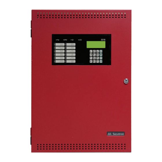
- Page 1 MR-400 Addressable Fire Alarm Control Panel All MGC MIX-4000 Series Detectors are not FM Approved LT-6671SEC Rev. 2 Installation and Operation Manual November 2023...
-
Page 3: Table Of Contents
Table of Contents FCC Notice Notice for all MR-400 Series Built-in UDACTs Sold in the U.S.A........FCC Notice ........................Introduction The MR-400 Addressable Fire Alarm Control Panel ............General Notes ........................ MR-400 Overview MR-400 Addressable Fire Alarm Control Panel Model ..........MR-400 System Components .................. - Page 4 LCD Display ........................Common LED Indicators and Control Buttons ............... Wiring Wiring Tables ......................... Wire Routing ........................Addressable Loop (Signaling Line Circuit) Wiring ............NAC Circuit Wiring ......................Module and Devices Wiring ................... Power Supply Wiring ...................... System Checkout ......................Troubleshooting ......................
- Page 5 List of Figures Figure 1 Model MR-400 Single Loop (SLC) Fire Alarm Control Panel ......... Figure 2 MR-400 Mechanical Installation Instructions and Dimensions ........Figure 3 Port and Jumper Locations on Main Board ..............Figure 4 Jumper on back of display ..................... Figure 5 Main Board with all Modules Installed ................
- Page 6 Numeric Keypad and Cursor Buttons ................Table 11 LED Indicators and Control Buttons ................Table 12 Secutron (MRI-4000 series) Devices Addressable Loop Wiring Table ......Table 13 NAC and Auxiliary Power Circuits Wiring Table ............. Table 14 Conventional Zone Module Input Circuit Wiring Table ...........
-
Page 7: Fcc Notice
01B represents the REN without a decimal point (for example, 01B is a REN of 0.1B). Secutron’s MR-400 SERIES BUILT-IN UDACT Digital Communicator described in this manual is listed by Underwriters Laboratories Inc. (ULI) for use in slave application in conjunction with a Listed Fire Alarm Control Panel under Standard 864 (Control Units for Fire Protective Signalling Systems). - Page 8 equipment which you have connected to your telephone line. Upon request of the telephone company, provide the FCC registration number and the ringer equivalence number (REN); both of these items are listed on the equipment label. The sum of all of the REN’s on your telephone lines should be less than five in order to assure proper service from the telephone company.
-
Page 9: Introduction
All MGC MIX-4000 Series Detectors are not FM Approved Introduction This document provides information for the successful installation and operation of the MR- 400 Addressable Fire Alarm Control Panel (FACP). The MR-400 Addressable Fire Alarm Control Panel Secutron’s MR-400 Addressable Fire Alarm Control Panel provides the following: •... -
Page 10: General Notes
General Notes Circuits Refers to a physical electrical interface for the analog loop, indicating signals or relays, and common alarm, supervisory, and trouble relay outputs. Zone/Group Is a logical concept for a Fire Alarm Protected Area, and will consist of at least one Circuit. The MR-400 uses zones to facilitate annunciation of multiple input and output points on the RAX- 1048TZDS (up to 96 points) and to facilitate the indication of bypass points. -
Page 11: Mr-400 Overview
MR-400 Overview This chapter lists all the possible components of an MR-400 addressable fire alarm control system. MR-400 Addressable Fire Alarm Control Panel Model The MR-400 Addressable Fire Alarm Control Panel has the following features: • Main Board, Power Supply and Backbox. •... -
Page 12: Mr-400 System Components
MR-400 System Components The following table describes the components of the MR-400 Addressable Fire Alarm Control System. Table 1 MR-400 System Components Model Description Model MR-400, black backbox, red door MR-400 enclosure comes complete with main board, power supply, transformer and main display. RAM-3318-LCD Remote Annunciator with 4-line LCD Display. - Page 13 Table 1 MR-400 System Components (Continued) Model Description Smart Relay Module with Red Enclosure. MR-2312-SR12 Can support up to 12 relays. Programmable Input Switches Module with 24 IPS-2424DS switches. Programmable Input Switches Module with 48 IPS-4848DS switches. RAM-1032TZDS Main Chassis Remote Annunciator with 16 bi-coloured LEDs and 32 trouble LEDs.
- Page 14 Table 1 MR-400 System Components (Continued) Model Description AGD-048 Adder Graphic Driver Module. Common Remote Trouble Indicator, Buzzer MR-2300T and LED. MMX-BB-1001D White Enclosure for one annunciator. MMX-BB-1001DR Red Enclosure for one annunciator. White enclosure for one annunciator rated for MMX-BB-1001WPA outdoor environment, wet location.
- Page 15 Table 1 MR-400 System Components (Continued) Model Description MP-300 End of line resistor plate. 3K9. 3.2.1 Devices Refer to document LT-1023SEC for compatible devices.
-
Page 16: Installation
Installation This chapter describes the installation of the MR-400. Mechanical Installation The MR-400 is suitable for flush or surface mounting with a built-in trim ring. Dimensions of Enclosure (minus built in trim ring) 14.5” x 4.25” x 21.14” Distance between horizontal mounting screws 12”... -
Page 17: Installation Tips
Installation Tips 1. Group the incoming wires through the top of the enclosure. For easy identification and neatness use a wire tie to group wires. 2. Be sure to connect a solid Earth Ground (from building system ground / to a cold water pipe) to the Chassis Earth Ground Mounting Lug, and to connect the Earth Ground Wire Lugs from the Main Chassis to the ground screw on the backbox. -
Page 18: Connections And Jumpers
Connections and Jumpers Auxiliary Unfiltered power Supply supply 1 Auxiliary Connection Notification power for remote Appliance Dialer line Dialer line supply 2 trouble Circuits 1 to 4 (resettable) indicator To printer JW11 To P4 on main display Main Board To PC Configurator JW10 Micro USB Port to PC Configurator... -
Page 19: Table 2 Main Board Connectors And Jumpers
Table 2 Main Board Connectors and Jumpers Connector/ Description Jumper RS-485 for annunciators and MR-2312-SR12/MR-2312-SW12 Auxiliary power supply 1, used to power the remote annunciators and smart relay modules (section 7.6.2) Trouble relay Alarm relay Supervisory relay Auxiliary relay Auxiliary power supply 2 (resettable) (section 7.6.2) Unfiltered supply (section 7.6.2) Connection for MR-2300T (section 7.4.4) TS10-TS13... -
Page 20: Figure 4 Jumper On Back Of Display
Table 2 Main Board Connectors and Jumpers (Continued) Connector/ Description Jumper JW10 Must be in the 1-2 position (bottom 2 pins) - allows PC connection through serial port JW11 Place in the 1-2 position (bottom 2 pins) for serial port or place in the 2-3 position (top 2 pins) for Keltron Dialer. -
Page 21: Installing Adder Modules
Installing Adder Modules The MR-400 Addressable Fire Alarm panel is shipped pre-assembled with all main components and boards. The following items can be installed in the field: • MR-2300-PR Polarity Reversal And City Tie Module • PCS-100 Power Supply Interface Board •... -
Page 22: Figure 6 Installing The Mr-2300-Pr Polarity Reversal And City Tie Module
The Trouble Transmit signal to the MR-2300-PR can be programmed to delay AC power fail 0, 1, 2, or 3 hours if this is the only system trouble. Mounting hole for #6-32 screws Mounting hole for #6-32 screws Reverse polarity and city tie module. -
Page 23: Figure 7 Ips-2424Ds Programmable Input Switches Module Front Chassis View
4.4.2 Installing the RAX-1048TZDS Display Adder Module The MR-400 can have a maximum of two RAX-1048TZDS Display Adder Modules. The RAX- 1048TZDS mounts in the MMX-BB-1000D series annunciator enclosures as part of the fire alarm system. No jumpers or other physical configuration steps are required to install the RAX-1048TZDS Display Adder Modules. -
Page 24: Figure 8 Ips-2424Ds Cable Connections
To Install the IPS-2424DS Programmable Input Switches Module 1. Mount the IPS-2424DS in the MMX-BB-1000D series enclosure and secure it with the hardware provided. 2. Disconnect main and standby power and connect the IPS-2424DS as shown in Figure 8. Ribbon Cable connects here on IPS-2424DS and goes to the next display module Ribbon IN. -
Page 25: Figure 9 Ips-4848Ds Programmable Input Switches Module Front Chassis View
4.4.4 Installing the IPS-4848DS Programmable Input Switches Module The IPS-4848DS Programmable Input Switches Module mounts in the MMX-BB-1000D series annunciator enclosures as part of the fire alarm system. This adder module provides 48 programmable switches, 48 bi-coloured (red/amber) LEDs for fire alarm zone annunciation and 48 amber trouble LEDs. -
Page 26: Annunciators
Annunciators Connect the annunciators to the RS-485 terminals and to auxiliary power. Use class B wiring for RS-485. For instructions, see the following Secutron documents: • RAM-3318-LCD: LT-1093MOD • RAM-1032TZDS(-CC) and RAX-1048TZDS(-CC): LT-617 • RAX-LCD-LITE: LT-1149 • MGD-32 and AGD-048: LT-847 MR-2312-SR12/MR-2312-SW12 Smart Relay Module Connect MR-2312-SR12/MR-2312-SW12 to the RS-485 terminals and to auxiliary power. -
Page 27: Operation
Operation This chapter describes the operational capabilities of the MR-400. Table 5 Settings Permitted in UL864 NOTICE TO USERS, INSTALLERS, AUTHORITIES HAVING JURISDICTION, AND OTHER INVOLVED PARTIES This product incorporates field-programmable software. In order for the product to comply with the requirements in the Standard for Control Units and Accessories for Fire Alarm Systems, UL 864, certain programming features or options must be limited to specific values or not used at all as indicated below. -
Page 28: Figure 11 Mgc-400 Configurator Date And Time Settings
Alarm conditions are determined by interrupt which uses thresholds for alarm conditions stored in the device. Secutron addressable detectors (MRI-4000 series) send an interrupt request to the panel, indicating the Alarm condition. The system is polling the interrupt group to determine the devices in Alarm. -
Page 29: Configurable Input Types
5.1.4 Drift Compensation Drift Compensation is built into Secutron MRI-4000 series addressable devices, and is not performed by the panel. Drift Compensation automatically adjusts for gradually increasing effects of dust and other accumulations of dirt in the detectors. It will adjust the thresholds to compensate for a detector going dirty according to the gradual change in the normal clean air value received. - Page 30 Table 6 Configurable Input Types (Continued) Device Types Dual Input Module Description Mini Dual Input Module As listed in located in Conventional Zone Input Type Configurator Section number Detectors Module Buzzer Silence Buzz Sil 5.2.7 Signal Silence Signal Silence 5.2.7 Acknowledge General Ack GA 5.2.7...
- Page 31 • Restoring the non-latching supervisory input returns all outputs correlated to the input, that are not correlated to another active input, to normal. • Zone display indicators update announcing the input is no longer active and removes the message from the shared display common queue. •...
- Page 32 • May also be programmed to relay, signal, and strobe outputs. Note: Trouble conditions initiated as a result of a trouble-only input activating is separate from the circuit or device supervision trouble. 5.2.6 Waterflow Alarm Input Waterflow inputs are sampled every second. 10 samples in alarm in any given 15 second period confirms the alarm condition.
-
Page 33: Output Types
5.2.10 Manual Day/Night Configures (mini) dual input modules for manual day/night alarm thresholds. For more information on alarm thresholds see 5.1.3 Alarm Conditions. 5.2.11 Auto Day/Night Configures (mini) dual input modules for auto day/night alarm thresholds. For more information on alarm thresholds see 5.1.3 Alarm Conditions. 5.2.12 Verified Alarm Input Unbypassed verified alarm inputs entering into alarm are verified over a period of time to... -
Page 34: Nac Circuit Operation
Additional Operation Features • The panel can synchronize strobes directly without the use of the synchronous module. • Depending on the device, the system can detect open and short troubles and report it as an output circuit trouble. 5.3.1 Signal Output For audible devices such as bells and piezo mini-horns, signals operate in alert (two stage) and/or evacuation rate. -
Page 35: Single Stage Operation
latching trouble. Since open circuit supervision does not operate while the circuit is in alarm, if the circuit was in trouble before it was activated, it will still indicate trouble while active. The trouble condition will be re-evaluated when supervision resumes. Output circuits configured as strobes can have sync protocol for synchronization if configured. -
Page 36: Evacuation Codes
Evacuation Codes The following Evacuation codes can be configured for the MR-400 FACP. Continuous On 100% of the time. Temporal Code 0.5 second on and 0.5 second off repeated 3 times 1.5s pause March Code 0.5 second on 0.5 second off. California Code 5 seconds on 10 seconds off. -
Page 37: Remote Annunciator Operation
• If Aux disconnect is not active, activates all non-disconnected indicating circuits programmed to the input. • Activates non-disconnected strobes associated with the input. • Activates non-disconnected signals associated with the input at the evacuation rate. In a preconfigured FACP the Positive Alarm Sequence may be enabled or disabled as the user requires. -
Page 38: Table 8 Annunciator Address Dip Switch Settings
Both shared display RAX-LCD-LITE and RAM-3318-LCD annunciators are connected to the panel via the RS-485 serial link (Class B). The maximum number of annunciators is seven (7). Configuration of the annunciators is done via the MGC-400 software configurator. Ensure that the address DIP switch on each annunciator is set to the same value set in the configurator. -
Page 39: Dialer Operation
5.8.4 Conventional Annunciators The MR-400 System is designed to interface with the RA-1000 series of conventional LED annunciators. The LEDs may be configured to zone status indicators. Each conventional annunciator contains a local alert buzzer. Under normal operation the alert buzzer is controlled by the system and operates in an identical manner as the one in the main panel. -
Page 40: Using The Operation Menu From The Control Panel
However, the system then does off-hook current monitoring supervision to ensure that the phone line is operational. 3. If there is an event to be reported in the dialer queue and the house phone is in use the dialer tries the second line to report the event. 4. -
Page 41: Figure 13 Operation Menu
How to Enter the Operation Menu 1. Press the Menu button. 2. Use the DOWN Cursor key to scroll to 3. Operation and press the Enter button to enter the Operation Menu. Operations 1 Set Time 2 Set Password 3 Reports 4 Clear logs 5 Walk test 6 Bypass... - Page 42 If an incorrect passcode is entered an invalid passcode message displays on the shared LCD. You have three attempts to enter the correct passcode. After three failed attempts the display reverts back to the main operation menu. Invalid passcode If the passcode is correct, enter the new passcode and press the Enter button. Enter new passcode To confirm the passcode, re-enter the passcode and press the Enter button.
- Page 43 If the panel does not have a printer connected or if you selected “Screen” under the “Report To” menu, only one address appears. Enter this address. Device address Loop: _ Addr: 1. Alarm log The alarm log report displays the contents of the alarm event log on the shared display which contains the last 400 of any of the following events: •...
- Page 44 The display shows the loop number, device address, the device type, device status, and the level of alarm, in the following format: Loop 1 Address 2 0001 000 0096 0032 (0% alarm) 1. Press the Up and Down cursor keys to scroll through all the devices on the loop. 2.
- Page 45 6. M/P Report The Secutron Protocol (MP) Report will display all local parameters of an Secutron Protocol device currently connected on the SLC. This feature will list the internal register values of current Secutron Protocol devices. Use this tool to report information to Secutron technical support.
- Page 46 • Other Relays and signal correlations to input circuits are not processed during walk-test. Correlations to system status will still be processed. • All common controls and keys not explicitly required for the walk-test operation are disabled while the walk-test is active. •...
- Page 47 Use the left and right arrow key to move through the outputs you want to active during walk test. Note: Each event during the walk test is also recorded in the log. Therefore, any event past the 200 count will clear the log and be entered as event 1 and so on. Walk Test Report When you stop the walk test, the system asks you to select an output for the report.
- Page 48 After the confirmation, the device is bypassed and the message appears that the device is bypassed. Device/circuit bypassed. If the device is already bypassed, the system prompts you to unbypass the circuit. FLOOR 4 ALARM L1- 0022 now bypassed. Unbypass? After the confirmation, the device is unbypassed and the information message shows that the device is unbypassed.
- Page 49 After the confirmation, the group is unbypassed and the message says that the group is unbypassed. Group unbypassed. 3. Loop The whole loop either conventional or addressable can be bypassed using this option. Enter the loop number to be bypassed. Loop number Loop: _ If the loop is not already bypassed, the system prompts you to bypass the loop.
-
Page 50: Table 9 List Bypass Special Characters
Loop number Loop: _ Next, enter the address list of devices you wish to bypass. Use the following symbols to enter the address list: Table 9 List Bypass Special Characters Symbol Number of times to Description press “1” key Sets the interval of consecutive addresses, e.g. 1-7. Separates the addresses of the devices Placed at the end of list to signify that no individual confirmation is required. - Page 51 At the end of the bypass operation or if the exclamation is used, the message shows: Done... 5. List Unbypass A list of devices can be bypassed using this option. The system prompts you to enter the loop number to be unbypassed. Loop number Loop: _ Enter the list to unbypass.
- Page 52 Common aux relays currently connected. Disconnect? Y After the confirmation the auxiliary relays are disconnected and the information message is displayed that the auxiliary relays are disconnected. Relays disconnected. If the auxiliary relays are already disconnected, you are prompted to reconnect the relays. Common aux relays now disconnected.
- Page 53 Select mode 1 Daytime 2 Nighttime A message appears showing that the day/night mode is updated. Day/Night mode updated. 5.10.10 Clear Verify Count This operation is used to clear all the verification counts accumulated during the alarm verification process. The system asks for confirmation as shown below. Clear all verification counters? Y...
- Page 54 An option to enable when the feature is available but has been bypassed: Pos Alarm disabled Enable? Y An option to disable when the feature is available and enabled: Pos Alarm enabled Disable? Y 5.10.13 Set Key Access This feature is not used. 5.10.14 Exit This feature exits to the main command menu.
-
Page 55: Indication & Controls
Indication & Controls This chapter describes the LED indicators and controls of the MR-400. Indication and Controls MR-400 Display Panel is equipped with the following: • 12 Control buttons with associated LEDs • 16 button Numeric Keypad with Cursor buttons Figure 14 below shows the LED indicators and control buttons on the MR-400 front display. -
Page 56: Figure 15 Numeric Keypad
6.2.1 Numeric Keypad and Cursor Buttons Figure 15 Numeric Keypad Table 10 Numeric Keypad and Cursor Buttons Description Key 2 (Up Cursor) Press this button to move the cursor or scroll up lists in a continuous loop. Key 4 (Left Cursor) Press this button to add or remove the X from an option in the Configuration menu. -
Page 57: Common Led Indicators And Control Buttons
Common LED Indicators and Control Buttons For complete descriptions of all LED indicators and control buttons see the following table. Table 11 LED Indicators and Control Buttons LED Indicator and Description Control Buttons AC On Indicator Illuminates steady green when the main AC power is within acceptable levels. The LED turns off when the level falls below the power-fail threshold and the panel is switched to standby (battery) power. - Page 58 Table 11 LED Indicators and Control Buttons (Continued) LED Indicator and Description Control Buttons Trouble Queue Button and Indicator Flashes yellow when any trouble condition is detected on the panel. The buzzer sounds at the slow rate. Pressing the Trouble Queue button allows the user to cycle through and review a list of active Troubles from oldest to most recent.
- Page 59 Table 11 LED Indicators and Control Buttons (Continued) LED Indicator and Description Control Buttons General Alarm Button and Indicator When pressed, this button will activate the panel into evacuation. The LED indicator will turn steadily red. Signal Silence Button and Indicator Flashes yellow at the Trouble Flash rate when Indication Circuits are silenced by the following: •...
- Page 60 Table 11 LED Indicators and Control Buttons (Continued) LED Indicator and Description Control Buttons Fire Drill Button and Indicator Illuminates steady yellow during an active Fire Drill. Pressing the Fire Drill button activates all programmed and non-Disconnected Indicating Circuits. It does not transmit any Alarms via the City Tie, or Common Alarm Relay.
-
Page 61: Wiring
S on the main board. Table 12 Secutron (MRI-4000 series) Devices Addressable Loop Wiring Table Wire Gauge Maximum Wiring Run to Last Device... -
Page 62: Table 13 Nac And Auxiliary Power Circuits Wiring Table
7.1.3 NAC and Auxiliary Power Supply Circuits Table 13 NAC and Auxiliary Power Circuits Wiring Table TOTAL MAXIMUM WIRING RUN TO LAST DEVICE (ELR) MAX. LOOP SIGNAL RESISTANCE 18AWG 16AWG 14AWG 12AWG LOAD Amperes Ohms 0.06 2350 3750 1143 6000 1829 8500 2591... -
Page 63: Wire Routing
Wire Routing Notes: All external connections are power limited except for the AC connections to the transformer. Transformer connections must be routed separately from all other external connections using their own conduit. All power limited wiring shall be routed through remaining knockouts. This knockout is to be used exclusively for AC input. -
Page 64: Addressable Loop (Signaling Line Circuit) Wiring
Addressable Loop (Signaling Line Circuit) Wiring Note: When an SLC device is powered by the AUX output, the supervision of the power pathway shall match the SLC pathway performance requirements. 7.3.1 Addressable Loop Wiring - Class B MULTI-SENSOR DETECTOR OUTPUT MODULE PHOTOELECTRIC SMOKE SENSOR PULL STATION... -
Page 65: Nac Circuit Wiring
7.3.3 Addressable Loop Wiring - Class X MULTI-SENSOR DETECTOR OUTPUT MODULE PHOTOELECTRIC SMOKE SENSOR MRI-4070 ISOLATOR TRI-MODE HEAT DETECTOR Figure 19 Addressable Loop Wiring - Class X NAC Circuit Wiring The MR-400 supports up to 4 NAC circuits that can be wired as either: •... -
Page 66: Figure 20 Nac Circuit - Class B Wiring
7.4.1 NAC Circuit – Class B Wiring CIRCUIT - 1 + + - - NAC CIRCUITS #2, #3 AND #4 ARE NOT SHOWN. NAC1 WIRE AS SHOWN ABOVE. BELL STROBE HORN EOL-392 Figure 20 NAC Circuit – Class B Wiring 7.4.2 NAC Circuit –... -
Page 67: Figure 22 Mr-2300T Common Remote Trouble Indicator Wiring
7.4.3 UL 864 Rev. 10 Addressable Supervised Output Module Wiring As per UL864 Rev.10 56.4.3, ensure that a single break, ground or wire-to-wire fault on the installation conductors of a signalling circuit for use with addressable notification appliances or modules shall not affect the operation of more than one notification zone. Exception: Riser conductors installed in accordance with the survivability from attack by fire requirements in National Fire Alarm Code, NFPA 72. -
Page 68: Module And Devices Wiring
Module and Devices Wiring 7.5.1 Dialer Wiring Wire the Dialer to the Public Telephone Switch and premises Telephone as shown in Figure 23. For information on Compatible DACR Receivers see Appendix A - Compatible Receivers on page 76. Public Switch Telephone Wiring RJ31X GREEN BROWN... -
Page 69: Figure 24 Connecting An Facp To A 3G4010Cf Interface Device Outside Canada
7.5.2 Connecting to a 3G4010CF Interface Device outside Canada For information on Compatible Receivers see Appendix A - Compatible Receivers on page 76. A typical connection is shown in Figure 25. The 3G4010CF is powered separately from the PCS-100 and requires 2 DSC RM-2 relays (sold separately). The PCS-100 Passive Communications Interface Board (sold separately) is also required. -
Page 70: Figure 25 Connecting An Facp To A Sle-Ltev Or Sle-Ltea Interface Device Outside Canada
7.5.3 Connecting to a NAPCO SLE-LTEV or SLE-LTEA Interface Device outside Canada For information on Compatible Receivers see Appendix A - Compatible Receivers on page 76. A typical connection is shown in Figure 25. The SLE-LTEV or SLE-LTEA is powered separately from the PCS-100. -
Page 71: Figure 26 Wiring The Mr-2300-Pr Polarity Reversal And City Tie Module
7.5.4 MR-2300-PR Polarity Reversal and City Tie Module Wiring Wire the MR-2300-PR Polarity Reversal and City Tie Module successfully as shown in Figure • Plug MR-2300-PR ribbon cable P1 into connector P8 on the Main Fire Alarm Board. • Remove jumper plug from JW7 on the Main Fire Alarm Board. •... -
Page 72: Power Supply Wiring
Power Supply Wiring 7.6.1 Main Power Supply Wiring Wire the Power Supply as shown in Figure 27 and adhere to the following: • Ensure that the AC supply is disconnected before wiring the power to the panel. • Wire the AC power to the AC wiring terminals as shown in Figure 27 using the proper wire gauge with 600 volt insulation and proper over current circuit protection that complies with local codes. -
Page 73: Figure 27 Main Power Supply Wiring And Connections
MR-400 Main Board MD-819 Power Supply Board Ribbon Cable Power Connector BLUE BLACK BLACK BATTERY BATTERY Figure 27 Main Power Supply Wiring and Connections 7.6.2 Supervision (Class B) of Auxiliary Supplies Aux 2 Resettable Auxiliary Power (supervised, regulated) The AUX 2 resettable auxiliary power supply is supervised for shorts. A short will: •... -
Page 74: Figure 28 Supervision Of Auxiliary Supplies
The circuit must be supervised for opens utilizing the End of Line Relay Model EOLR-1 as shown in Figure 15. This supply is rated at 24VDC regulated/500mA max/1V voltage drop maximum. Unfiltered Supply (unsupervised, unregulated) This unregulated supply is not supervised. When supervision is required, the circuit must be supervised for opens utilizing the (UL listed - S3705) End of Line Relay Model EOLR-1. -
Page 75: System Checkout
System Checkout The following are the recommended steps before and during the powering up of the MR-400. 7.7.1 Before Turning The Power ON 1. To prevent sparking, DO NOT connect the batteries first. Connecting the batteries is only to be done after the system has been powered from the main AC Supply. 2. -
Page 76: Appendix A - Compatible Receivers
Appendix A - Compatible Receivers The built-in dialer in the MR-400 Fire Alarm Control Panel is compatible with the following Digital Alarm Communicator Receivers (DACR) listed: Table 16 Compatible DACR Receivers DACR Receiver Model Protocols SurGard MLR2 Multi-Line Receiver (ULI Approved) SIA Format Protocol and SIA Contact ID SurGard SLR Single-Line Receiver (ULI Approved) SIA Format Protocol and SIA Contact ID... -
Page 77: Appendix B - Manual Panel Configuration
Appendix B - Manual Panel Configuration COMMAND MENU The command menu is the first menu displayed for command mode. The command menu is divided into four main sub menu categories, the configuration allows full front panel configuration of the system and the operation menu performs certain operations which may not be possible using the common control switches and indicators on the front panel. - Page 78 PANEL CONFIGURATION/1. FEATURES The features described are the overall features of the system and their impact is system wide. The default setting in some features is shown as selected. Panel Configuration/Features/Manual Signal Silence Manual Signal Sil. [x] Enabled The manual signal silence option will allow silencing of the signal, from the common control signal silence switch, when they are active.
- Page 79 This feature applies to the main panel powered output circuits, configured as strobes, only. Note: Once a specific type of strobe is selected, for example Secutron, then only this type of strobe is allowed for the entire system. Panel Configuration/Features/Evacuation code Evac.
- Page 80 [x] Temporal [ ] California Select the evacuation code for the 2nd stage in a two stage system and for the 1st stage in a single stage system. Panel Configuration/Features/Building alert Bldg. alert [ ] Enabled Alert sounds for building input activation. The default is disabled. Panel Configuration/Features/Device LED flashing Dev.
- Page 81 ______ PANEL CONFIGURATION/4. USER MESSAGE Allows you to edit (change) the FACP Front Panel Message, for example “Welcome to Secutron”. PANEL CONFIGURATION/5. LANGUAGE Allows you to select the language of the LCD display. English is the default. To change the language to French, select French in the panel configuration menu, then exit the configuration and then re-enter and select auto default.
- Page 82 1. Wire the MRI-4000 devices to the panel and power up the panel (as described in section 7.7 on page 75). 2. On the display, select 4. Reset Config. Reset Configuration? Y (N) 3. Select Y. 4. Connect the MGC-400 Configurator to the panel and get the job. 5.
-
Page 83: Appendix C - Reporting
10.0 Appendix C - Reporting 10.1 Ademco Contact-ID MR-400 Series Event Codes Table 17 Contact-ID Event Codes Event Description Event Qualifier Code Group # Contact # Family Phone Line #1 trouble detected Trouble New event 1 351 Phone Line #2 trouble detected Trouble New event 1 352... -
Page 84: Security Industries Association Sia Format Protocol Mr-400 Series Event Codes
10.2 Security Industries Association SIA Format Protocol MR-400 Series Event Codes SIA Format Protocol does not define indicating zone troubles, but lists it as Untyped Zone Trouble/Restore. Table 18 SIA-DCS Event Codes Event Description Event Family Qualifier SIA Event Code Parameter Phone Line #1 trouble detected Trouble New event... -
Page 85: Appendix D - Specifications
0.7A rating at full load Addressable loop Secutron Protocol SLC loop with 240 addressable devices. Maximum loop resistance depends on number of devices and device type. For a complete list of compatible devices see LT-1023SEC Compatible Devices Guide. Power Limited / 24V DC / 350mA alarm maximum / 0.5 μF Power Limited / 24V DC / 280mA normal standby maximum / 0.5 μF... -
Page 86: Mr-400 System Module And Annunciator Specifications
Table 19 MR-400 Specifications (Continued) MR-400 Fire Alarm Control Panel Auxiliary relays Common Alarm/ Must be connected to a listed power limited source of Supv./Trouble/ supply, Form C/28VDC/1A max Auxiliary Alarm RS-485 port For remote annunciators. Terminals are labelled “RS-485” Ground Fault 10 K Ohms Impedance... -
Page 87: Appendix E - Battery Calculations
12.0 Appendix E - Battery Calculations IMPORTANT NOTICE The main AC branch circuit connection for Fire Alarm Control Unit must provide a dedicated continuous power without provision of any disconnect devices. Use #12 AWG wire with 600-volt insulation and proper over-current circuit protection that complies with the local codes. -
Page 88: Table 21 Recommended Batteries
Total Alarm Current must be 5 amperes or less. NAC Circuits must not exceed 5 amperes. Battery Selection Battery Size = Multiply (C) by 1.20 to derate battery. See the following table for the recommended Secutron batteries for use with this panel Table 21 Recommended Batteries Battery Model... -
Page 89: Warranty And Warning Information
Please read this document CAREFULLY, as it contains important warnings, life-safety, and practical information about all products manufactured by the Mircom Group of Companies, including Mircom and Secutron branded products, which shall include without limitation all fire alarm, nurse call, building automation and access control and card access products (hereinafter individually or collectively, as applicable, referred to as “Mircom System”). - Page 90 The testing should include all sensing devices, keypads, consoles, alarm indicating devices and any other operational devices that are part of the system. NOTE TO USERS: All Mircom Systems have been carefully designed to be as effective as possible. However, there are circumstances where they may not provide protection.
- Page 91 13. Wireless Devices Placement Proximity. Moreover all wireless devices must be a minimum and maximum distance away from large metal objects, such as refrigerators. You are required to consult the specific Mircom System manual and application guide for any maximum distances required between devices and suggested placement of wireless devices for optimal functioning.
- Page 92 CANADA - Main Office U.S.A © Secutron 2023 25 Interchange Way Printed in Canada 4575 Witmer Industrial Estates Subject to change without prior notice Vaughan, ON L4K 5W3 Niagara Falls, NY 14305 Tel: (905) 660-4655 Tel: (905) 660-4655 www.secutron.com (888) 660-4655...
Need help?
Do you have a question about the MGC MIX-4000 Series and is the answer not in the manual?
Questions and answers