Table of Contents
Advertisement
Quick Links
Advertisement
Table of Contents

Related Manuals for JTS UF-10R


Summary of Contents for JTS UF-10R
- Page 1 UF-10R / UF-10TH / UF-10TB PROFESSIONAL CO., LTD No.148, Gongye 9th Rd., Dali Dist., Taichung Professional Wideband (60~75MHz) City 41280, Taiwan (R.O.C.) Tel: 886-4-24938803 Fax: 886-4-24914890 True Diversity System Email: jts@jts.com.tw www.jts.com.tw 59508-040-04...
- Page 2 UF-10TB UF-10R UF-10TH UHF PLL Product manual...
- Page 3 One year product warranty Equipment Product Model serial number Customer Contact name number Address Purchase date Selling store Be sure to put store stamp and fill in purchase date for the warranty to be stamp effective! Warranty description 1. Be sure to put the warranty label indicating purchase date on the bottom of equipment to ensure your interest in maintenance and service.
-
Page 4: Table Of Contents
3-3 Body-Pack Transmitter // UF-10TB ............5 3-4 Optional Condenser Microphone 4. Parts Identification & Accessories ......8 ................8 4-1 Receiver // UF-10R ........... 11 4-2 Handheld Transmitter // UF-10TH ..........12 4-3 Body-Pack Transmitter // UF-10TB ........... 13 4-4 Optional Condenser Microphone .................. -
Page 5: System Operation Instructions
2-1 UHF PLL Broadband true diversity receiver // UF-10R The UF-10 Wide Band Wireless Microphone System uses the latest wireless technology can be found. Up to 75 MHz bandwidth benefits multi system application. JTS patented REMOSET provides great convenience to project set up. Various advanced features assure a successful performance. -
Page 6: Handheld Transmitter // Uf-10Th
2-2 UHF PLL Handheld transmitter // UF-10TH • Maximum 2400 to 3000 selectable frequencies across 60~75 MHz. • Phase-locked loop circuit design. • Extended dynamic range and smooth frequency response. • Tone key squelch. • Replaceable condenser or dynamic capsule module. •... -
Page 7: Specification
3. Specification 3-1 UHF PLL Broadband true diversity receiver // UF-10R Frequency oscillation mode PLL Synthesized Control REMOSET........Radio Frequency Carrier frequency range..502~960 MHz Signal to noise ratio....> 105dB Total distortion rate....<0.6%@1KHz Function display method..LCD and LED Function display content.. -
Page 8: Handheld Transmitter // Uf-10Th
3-2 UHF PLL Handheld transmitter // UF-10TH Frequency oscillation mode PLL Synthesized Control Carrier frequency range..502~960MHz RF output......... 10mW/50mW (Depend on Local Regulation) Stability..........< ±10KHz Frequency drift......±48KHz LCD............. Frequency (up/down) , Power indicator , Device ID Control method......Power switch , AF , Frequency (up/down) , Lock-On , ID pairing Spurious Emissions.... -
Page 9: Optional Condenser Microphone
3-4 Optional Condenser Microphone Lavaliere Microphone Model No....... CM-501 CM-201i CM-125i Connector......4P Mini XLR 4P Mini XLR 4P Mini XLR Frequency Response..100~15,000 Hz 60~15,000 Hz 50~18,000 Hz Polar Pattern......Cardioid Omni-directional Omni-directional Sensitivity (at 1000Hz) -60±3 dB -60±3 dB -53±3 dB Impedance...... - Page 10 Headset Microphone Model No....... CM-214i CM-214Ui CM-214ULi Connector....... 801C4 801C4 801C3 (3P Mini XLR) 801C4 (4P Mini XLR) (4P Mini XLR) (4P Mini XLR) 801CS (3.5 stereo plug) Option Connector... 801C3 801C3 801CR (3P Mini XLR) (3P Mini XLR) 801CS 801CS (3.5 stereo plug) (3.5 stereo plug)
- Page 11 Ear-hook Microphone Model No....... CM-801/CM-804i CM-8015/CM-825i Connector......801C4 (4P Mini XLR) 801C4 (4P Mini XLR) Option Connector... 801C3 (3P Mini XLR) 801C3 (3P Mini XLR) 801CS (3.5 stereo plug) 801CS (3.5 stereo plug) 801CR 801CR Frequency Response..60~15,000 Hz 50~18,000 Hz Polar Pattern......
-
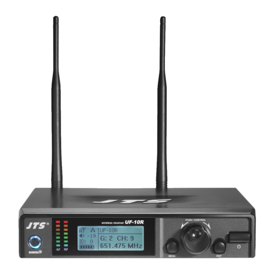
Page 12: Receiver // Uf-10R
Power switch: press switch once to turn power on; press and hold for 2 seconds to shut down. EXIT key: when UF-10R is under “setup menu”, press EXIT to cancel selection or leave menu. Jog dial: on “setup menu” screen, turn jog dial to select setup item, after entering into the selected item turn jog dial to adjust the value. - Page 13 (2) Receiver LCD instruction : indicate key lock is set (Key lock on). : show antenna A or B is receiving signal; signal is not received : indicate current receiver volume. : indicate device ID setting: ID number 0~255. : indicate transmitter battery level; if no RF signal is received will show G: indicate current Group, 1~13 CH: indicate current Channel, CH1~63...
- Page 14 (3) Rear panel Power receptacle: connect to power supply (DC12V/1000mA) Balanced XLR MIC output Ø 6.3mm balanced output BNC antenna socket: ANT 1 and ANT 2, set antennas vertical or sloping for better reception. Freq.Range: CAUTION RISK OF ELECTRIC SHOCK DO NOT OPEN 1856 Made in Taiwan...
-
Page 15: Handheld Transmitter // Uf-10Th
4-2 UHF PLL handheld transmitter key function and LCD description // UF-10TH Power key: Turn on power: press power key once Shut down power: press and hold power key for 2 seconds , : up and down keys, select setup item. Press and hold both keys for 2 seconds will mute or release the mute of the microphone. -
Page 16: Body-Pack Transmitter // Uf-10Tb
4-3 UHF PLL Body-Pack Transmitter // UF-10TB Battery Low Battery Indicator: when battery lever is low this red LED will light on constantly. Note: when switch on the unit the red LED will light on for 1 second and turn off. AF Peak and Mute Indicator AF PEAK: Orange Mute mode: Red light flashes... -
Page 17: Optional Condenser Microphone
4-4 Optional Condenser Microphone Lavaliere Microphone // CM-501 / CM-201i / CM-125i Clip 4 Pin Mini XLR Windscreen CM-501 CM-201i CM-125i Professional Wideband (60~75MHz) True Diversity System... - Page 18 Headset Microphone // CM-214i / CM-214Ui / CM-214ULi / CM-235i / CX-504 Gooseneck Adjustable headband Headband 4 Pin Mini XLR Windscreen CM-214i CM-214Ui CM-214ULi Standard : 4 Pin Mini XLR 3 Pin Mini XLR 3.5 Stereo Plug CM-235i CX-504...
- Page 19 Ear-hook Microphone // CM-801 / CM-804i / CM-8015 / CM-825i Boom Adjustable Headband Adjustable ear hook Detchable Cable Cable Clip CM-801 Windscreen 4 Pin Mini XLR Option 3 Pin Mini XLR 3.5 Stereo Plug Option 4Pin Hirose connecter Option CM-804i CM-8015 CM-825i Professional Wideband (60~75MHz) True Diversity System...
- Page 20 Compatible Instrument Microphone // CX-500 / CX-500F / CX-520 / CX-508W / CX-516W Gooseneck Clip Bracket Volume Control Windscreen 4 Pin Mini XLR CX-500 CX-500F CX-520 CX-508W CX-516W...
- Page 21 4-5 Accessories AC/DC power adapter: Switching power adapter AC IN: AC100~240V/50~60Hz DC OUT: DC12V/1000 mA Audio cable Rack mount kit//RM-10 (optional) RM-10E RM-10M Rack mount kit//RM-901 (optional) Professional Wideband (60~75MHz) True Diversity System...
-
Page 22: Connection Method
1. UF-10R output to a mixer or an amplifier: Audio cable: XLR or Ø 6.3mm audio cable, one end connects to audio output of UF-10R “AF OUTPUT BALANCED”, while the other end connects to audio input of a mixer or an ampli- fier. - Page 23 3. Receiver rack mount kit assembly//RM-10 (optional) (1) Assembly the rack mount kit as the following illustration to mount two UF-10R into one U rack. (2) Lock equipment onto a rack Professional Wideband (60~75MHz) True Diversity System...
- Page 24 4. Rack Mount Kit RM-901 (optional) • Mount one UF-10R into one U rack. (1) Screw the rack mount kit on the receiver. (2) screw the whole set onto a rack.
-
Page 25: Operation
6. Operation 6-1 Operation setup for broadband true diversity receiver system // UF-10R 1. Turn receiver power on (1) Connect antennas onto the receiver (2) Press power key once to turn power on (3) Shut down: press and hold power key for 2 seconds. - Page 26 (2) When microphone receives data, microphone indicator lamp shows blue light for 5 seconds, while receiver blue light stops flashing, indicating the REMOSET has been done successfully . (Fig. 2) Fig. 2 (3) Receiver blue light flashes slowly, indicating REMOSET failure, please check it: 1) Whether “frequency range labels”...
- Page 27 1. Frequency: set frequency 1. Frequency (1) Turn jog dial to “1. Frequency”, press Setup (or press jog dial) 2.Group/Channel 3.User Group to enter into frequency adjustment screen. 4. Scan (2) After entering into frequency adjustment screen, first adjust left Setup Frequency 3 digit frequency;...
- Page 28 3. User Group: user self-defined group and channel 1. Frequency Turn jog dial to “3. User Group”, press Setup (or press jog dial) to 2.Group/Channel 3.User Group enter into User Group setup screen. 4. Scan #1. Custom Group: self-defined group 1.
- Page 29 4. Scan: scan channel 1. Frequency (1) Turn jog dial to “4. Scan”, press Setup (or press jog dial) to 2.Group/Channel 3.User Group enter into scan channel screen. 4. Scan #1. All Groups: scan all groups 1. All Groups (1) Turn jog dial to “1. All Group”, press Setup (or press jog dial) 2.
- Page 30 #3. Current Group: scan single channel 1. All Groups (1) Turn jog dial to “3. Current Group”; press jog dial to enter 2. Result List 3. Current Group into menu screen. 4. Return Scan Current Group (2) Turn jog dial to select Group first; press Setup key (or press CH:1 jog dial) to start scan.
- Page 31 (2) Turn jog dial to adjust ID, ranging 0~255; press Setup key to Setup Device ID save setting. 6 (0~255) The setting will affect the use of REMOSET. 7. Volume: Adjust volume 5. Squelch 6. Device ID (1) Turn jog dial to “7. Volume”, press Setup (or press jog dial) to 7.
- Page 32 User Name (2) Turn jog dial to select desired character; after confirmation press jog dial to go to next character setup; after setup press JTS UF-10R Setup key to save setting. Char:1/10 A user name consists of 10 characters at maximum.
- Page 33 c. Key Lock: set key lock a. User Name (1) Turn jog dial to “c. Key Lock”, press Setup (or press jog dial) b. Contrast c. Key Lock to enter into setup screen. d. Exit (2) Turn jog dial to select “Lock On”; after confirmation press Setup Key Lock Setup key to save setting;...
-
Page 34: Handheld Transmitter // Uf-10Th
6-2 System operation setup for handheld transmitter // UF-10TH 1. Turn power on for UF-10TH handheld transmitter (1) Turn on power: press power key once (Fig. 3). (2) Shut down power: press and hold power key for 2 seconds. Fig. 3 (3) Back: At setting or menu screen pressing of POWER key will bring the screen back to menu or home screen respectively. - Page 35 (3) Adjust right 3 digit frequency: press keys with “+/-” 0.025 MHz as Frequency unit change; after adjustment press SET key to save setting. G:- - C:- - 638.100 Freq. 2. ) Group: set group and channel Group (1) Press keys to Group;...
- Page 36 5. ) Device ID: set device ID Device ID (1) Press keys to Device ID; press SET key to enter into “Device ID” Remoset RF Power setup screen. Contrast Device ID (2) Press keys to adjust default ID between 0 and 255; press SET key to switch to set ID: ON/OFF.
- Page 37 8. ) Contrast: adjust screen contrast Remoset (1) Press keys to Contrast; press SET to enter into “Contrast” screen; RF Power Contrast adjust screen contrast. Light T. (2) Press keys to adjust contrast; higher number represents higher Contrast contrast; otherwise, lower contrast; -3 ~ 0 ~ +3 total seven adjustable levels.
- Page 38 11.) Key Lock: set key lock Name (1) Press keys to Key Lock; press SET to enter into “Key Lock” screen; Key Lock Exit set key lock -------------- Key Lock (2) Select “Lock On” to lock all keys to prevent accidental touch. Lock On Lock Off (3) If setting is “Lock On”, pressing any keys will prompt the following screen.
-
Page 39: Body-Pack Transmitter // Uf-10Tb
6-3 System operation setup for Body-Pack transmitter // UF-10TB 6-3-1 Turn power on for UF-10TB Body-Pack transmitter (Fig. 5) (1) Turn on power: press power key once (2) Shut down power: press and hold power key for 2 seconds. (3) Mute setup : When microphone is in use and mute setup is needed: Set mute: short press power key once;... - Page 40 2. Group: set group and channel Group (1) Press keys to Group; press SET key to enter into “Group” setup screen. Sensit. Attenuate Device ID (2) After entering into the screen, press keys to select the desired group ; Group/Chan press SET key to switch to Channel setup.
- Page 41 5. Device ID: set device ID Device ID (1) Press keys to Device ID; press SET key to enter into “Device ID” setup Remoset screen. RF Power Contrast Device ID (2) Press keys to adjust default ID between 0 and 255; press SET key to switch to set ID: ON/OFF.
- Page 42 7.RF Power: set transmission power RF Power (1) Press keys to RF Power; press SET to enter into “RF Power” screen;set Contrast Light T. transmission power. Name (2) Press keys to select transmission power as Hi or Low; press SET key RF Power to save setting.
- Page 43 10.Name: set user name Name (1) Press keys to Name; press SET to enter into “Name” screen; set user Key Lock Exit name. (2) Press keys to select texts; after confirmation press SET key to set the next User Name UF-1 character;...
- Page 44 Plug the connector into input socket on the body-pack transmitter. MIC IN UHF PLL Transmitter (3) Instrument Microphones The system is compatible with JTS various instrument microphones. For detail please refer to user’ s manuals of these microphones.
- Page 45 (4) Ear-hook Microphone 1. Lightweight Dual Ear Hook Microphone Try on whether the headset is fit. Adjust the headband to a suitable width. Tighten or loosen the curve of the ear-hook by twisting the loop or expanding it. Curve and bend the boom to fit your face. Attach the detachable cable to a suitable place by a cable clip.
-
Page 46: Product Notes
(4) It is suggested to hold the middle section of transmitter (microphone) body to achieve the best pickup effect. (5) When multiple units are in use, it is suggested to use JTS UA-900 antenna distributor to prevent interference. (6) When transmitter is not used for a long time, please remove batteries from battery compart- ment to avoid leakage of electrolyte solution to damage transmitter. -
Page 47: Important Notice
8. Important Notice (1) JTS offers wireless systems in a selection of bands that conform to the different government regulations of specific nations or geographic regions. These regulations help limit radio frequency (RF) interference among different wireless devices and prevent interference with local public communications channels, such as television and emergency broadcasts.