Table of Contents
Advertisement
Quick Links
Advertisement
Table of Contents

Related Manuals for JTS UT-16G3


Summary of Contents for JTS UT-16G3
- Page 1 Lighter Smaller More Powerful GUITAR / ACCORDING / WINDS / BRASS PROFESSIONAL CO., LTD. No. 148, 9th Industry Road, Ta-Li Industrial Park, Taichung City, Taiwan, R.O.C. Tel: 886-4-24938803 Fax: 886-4-24914890 E-mail: jts@jts.com.tw 59508-XXX-01 www.jts.com.t w...
- Page 2 music Miniature instruments wireless system Instruction Manual...
- Page 3 Thank you for choosing the JTS wireless system. In order to obtain the best efficiency from the system, you are recommended to read this instruction manual carefully.
- Page 4 4-1-1 Receiver // RU-8011D 4-1-2 Receiver // RU-8011DB 4-1-3 Receiver // RU-8012DB 4-1-4 Receiver // RU-12 4-1-5 Receiver // RU-901G3 4-2 Miniature Transmitter // UT-16G3 4-3 Accessorie 5. Preparing Procedures & Basic Operation 5-1 Receiver 5-2 Battery Insertion of The Transmitter 5-3 Install The Transmitter 6.
-
Page 5: Important Caution
When multiple receivers are stacked at the same time, it is advised to select frequency points in the same group to avoid frequency interference. 2. Features The newly designed UT-16G3 wireless instrument microphone is equipped with JTS patented technology with the ultrasonic wireless transmission function for users to choose wireless synchronization parameters or set parameters manually. -
Page 6: Specification
3. Specification 3-1-1 UHF PLL single/dual-channel diversity receiver // RU-8011D(DB) / RU-8012DB Model Frequency Oscillation Mode Phase-locked loop (PLL) Carrier Frequency Range 470~960 MHz Remoset Frequency Ultrasonic Diversity Antenna diversity Bandwidth 36MHz Signal/Noise Ratio >105dB(A) Total Harmonic Distortion (Thd) <0.6%@1KHz Receiving Sensitivity -95dBm ,... - Page 7 3-1-2 UHF PLL dual-channel diversity receiver // RU-12 Model Frequency Oscillation Mode Phase-locked loop (PLL) Carrier Frequency Range 470~960 MHz Remoset Frequency Ultrasonic Diversity Antenna diversity Bandwidth 36MHz Signal/Noise Ratio >105dB(A) Total Harmonic Distortion (Thd) <0.6%@1KHz Receiving Sensitivity -95dBm , S/N>80dB Image Rejection Ratio >80 dB Frequency Response...
- Page 8 3-1-3 UHF PLL single-channel True Diversity receiver // RU-901G3 Frequency Oscillation Mode Phase-locked loop (PLL) Carrier Frequency Range 470~960 MHz Remoset Frequency Ultrasonic Diversity True diversity Bandwidth 36MHz Signal/Noise Ratio >105dB(A) Total Harmonic Distortion (Thd) <0.6%@1KHz Receiving Sensitivity -95dBm , S/N>80dB Image Rejection Ratio >80 dB Frequency Response...
- Page 9 3-2 Miniature Transmitter // UT-901G3 Model UT-901G3 Frequency Oscillation PLL Synthesized Control Mode Carrier Frequency Range 470~960 MHz Frequency Setting Ultrasonic / Remoset U (Receive) RF Outputs Maximum 10mW Stability <±10KHz@Fc Frequency Deviation ±48KHz Spurious Emissions <-50dBc Power ON/OFF, Mute, Group,Channel, Frequency, Sensitivity, Key Function Lock Display...
-
Page 10: Part Identification & Accessories
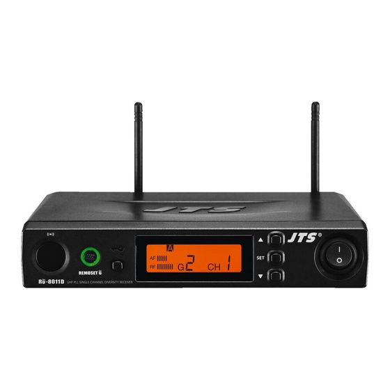
4. Part Identification & Accessories 4-1-1 UHF PLL single-channel diversity receiver // Front panel Rear panel Antenna A Antenna B 100mA 100mA Power: means “ON” and means “OFF” SET: this is for function settings. Push and hold for 2 seconds to enter the setting mode. - Page 11 LCD Display In the non-setting mode, the LCD looks like : : Audio signal strength : RF signal strength : Antenna A/B : Group / channel : Button lock engaged : Receiver mute MINIATURE MUSIC INSTRUMENT WIRELESS SYSTEM...
- Page 12 4-1-2 UHF PLL single-channel diversity receiver // Front panel Rear panel : See page 5. Female BNC antenna port: the 50Ω BNC antenna is connected here. It also provides a booster power of 12~15 DC / 100mA for an external antenna booster.
- Page 13 LCD Display In the non-setting mode, the LCD looks like : : Audio signal strength : RF signal strength : Antenna A/B : Transmitter battery level : Group/channel : Volume : Button lock : Receiver mute : Output attenuation : Frequency MINIATURE MUSIC INSTRUMENT WIRELESS SYSTEM...
- Page 14 4-1-3 UHF PLL dual-channel diversity receiver // Front panel Rear panel : See page 5. Female BNC antenna port: the 50Ω BNC antenna is connected here. It also provides a booster power of 12~15 DC / 100mA for an external antenna booster.
- Page 15 LCD Display In the non-setting mode, the LCD looks like this: : Audio signal strength : RF signal strength : Antenna A/B : Transmitter battery level : Frequency (group/channel) : Receiver mute : Output attenuation : Frequency MINIATURE MUSIC INSTRUMENT WIRELESS SYSTEM...
- Page 16 4-1-4 UHF PLL dual-channel diversity receiver // Front panel UHF PLL DUAL CHANNEL DIVERSIT Y RECEIVER R -12 Power: means “ON” and means “OFF” SET: this is for function settings. Push and hold for 2 seconds to enter the setting mode.
- Page 17 Rear panel Serial No.: Freq.: DCV INPUT Made In Taiwan Mixed 12-15V/500mA ANT.A ANT.B AF OUTPUT BALANCED AF OUTPUT BALANCED Female BNC antenna port: the 50Ω BNC antenna is connected here. It also provides a booster power of 12~15 DC / 100mA for an external antenna booster.
-
Page 18: Volume Control
4-1-5 UHF PLL single-channel diversity receiver( True Diversity ) // RU-901G3 Front panel Power On/Off switch: Press once to turn on the power,press and hold for 2 seconds to turn offf. SET: this is for function settings. Push and hold for 2 seconds to enter the setting mode. - Page 19 In the non-setting mode, the LCD looks like : : Antenna A/B : Transmitter battery level : Group/channel : Key Lock : Receiver mute : Output attenuation : Squelch level : Frequency Rear panel DC power socket: for 12~15V DC / 500mA power supply Female BNC antenna port: the 50Ω BNC antenna is connected here. It also provides a booster power of 12~15 DC / 100mA for an external antenna booster.
- Page 20 4-2 Miniature Transmitter Power button/mute button: On: Press the button to turn on the power and press it again for the mute mode Off: Press the power button for 2 seconds until the screen shows power off Ultrasound receiving hole: receiving binding signals from the ultrasound trans- mitting unit of the receiver.
- Page 21 Display content in non-set mode: : RF emission instruction : KeyLock ON : Battery indicator : DigiCode ON : Mute ON : Frequency MHz MINIATURE MUSIC INSTRUMENT WIRELESS SYSTEM...
- Page 22 4-3 Accessories AC/DC transformer Switching power supply (100V~240V , 50~60Hz) Linear power supply (220V, 50Hz) Linear power supply (220V, 60Hz) AF output wire Regulating rod Chuck DR-900 dual-hole receiver holder Optional RP-900 holder hood Optional Double-faced tape *2 Windscreen ※ Apply double-faced tape to the upper and lower covers of the audio head to prevent the windshield from falling off easily.
-
Page 23: Preparing Procedures & Basic Operation
AF OUTPUT OUTPUT CAUTION LEVEL DCV INPUT RISK OF ELECTRIC SHOCK BALANCED DO NOT OPEN 12-18V/200mA Freq.Range: JTS PROFESSIONAL CO., LTD. No. 148, 9th Industry Road, Ta-Li Industrial Park, Taichung City, Taiwan, R.O.C. -20dB UNBALANCED MINIATURE MUSIC INSTRUMENT WIRELESS SYSTEM... - Page 24 5-2 Install transmitter battery (1) Press the battery cover and slide out. (2) Insert or replace a battery based on its polarity. (3) Switch the power to ON. If the battery level is high, the LED indicator will emit green light. Once the battery is low, the LED indicator will turn red, and the remaining power will last only 30 minutes.
- Page 25 5-3 Install transemitter (1) Use UT-16G3+6.3GT plug in electric guitar 1. Insert the 6.3GT plug into the transmitter and screw it to the end. 2. Insert the transmitter into the output hole of the electric guitar sound so urce. 3. When inserted into the output hole of the electric guitar sound source, the transmitter should be pushed to the end to fix it.
- Page 26 (2) Use 516GT/508GT for wind instruments/accordions Insert 516GT/508GT into the transmitter and screw it firmly to the bottom. Turn the screw on the 16GT Adapter/16GT CLIP/ CLP-UT clockwise to attach the transmitter to the instrument. Fix 16GT Adapter + 516 Bracket on the accordion. Secure 16GT CLIP/CLP-UT to proper position Adjust 516GT/508GT to appropriate position...
-
Page 27: System Operation
6. System Operation 6-1-1 Operation // UT-16G3 Parameter setting Press SET button for 2 seconds to enter the set menu, press▲/▼to select the item to be set, and press SET for setting. ◎ FREQ frequency setting Unit: 1MHz Press▲/▼to set frequency Unit: 0.025MHz... - Page 28 ◎ Digital audio code Function is deactivated Function is activated ◎ Reset Reset to original manufacture settings Cancel ◎ Key lock Loc OFF Lock OFF Loc SET Only lock the setting function; power and mute control are avail- able Loc ALL Lock all keys, power and mute control are not available Unlocking...
- Page 29 Binding When relevant parameters are set, press the key to transmit the digital binding data to the transmitter by using the ultrasonic transmitter, while setting relevant parameters synchronously. When data is being transmitted, the indicator flashes quickly. When the synchronization is completed, the receiver receives the corresponding channel or frequency, and the light will stop immediately.
-
Page 30: Parameter Setting
6-1-2 How to use // Parameter setting Push and hold the “SET” button to enter the setting mode. ◎ Group / channel setting G: group Select default group 1~6 CH : channel Select default channel, 1~22 Select the group when “G” is flashing; select the channel when “CH”... - Page 31 ◎ Microphone input sensitivity Normal sensitivity SE A:+15dB SE 9:+12 dB SE 8:+9dB SE 7:+6dB SE 6:+3 dB Normal default sensitivity SE 5:0 dB SE 4:-3 dB SE 3:-6 dB SE 2:-9 dB SE 1:-12 dB SE 0:-15 dB 20dB SE AA:-5 dB attenuation SE A9:-8 dB...
- Page 32 6-1-3 How to use // Parameter setting Push and hold the “SET” button to enter the setting mode. Push the ▲/▼ button to choose to set RX (receiver) or TX (transmitter). When RX receiver is selected: ◎ FREQ: frequency setting In 1MHz Select frequency with ▲/▼...
- Page 33 ◎ Audio output attenuation (XLR) At oFF No attenuation at audio output At on 20dB attenuation at audio ouput This function is deactivated. ◎ SQ Receiving sensitivity -5~+10dB; -5 is the maximum sensitivity. select +10 is the minimum sensitivity. SQ with The default setting is 0.
-
Page 34: Volume Adjustment
◎ATOF: Automatic microphone off countdown under mute status AO OF This function is deactivated AO 1 1 minute countdown to turn off AO 10 10 minute countdown to turn off AO 30 30 minute countdown to turn off This function is deactivated. (The default setting is 10 minute.) ◎RFP: RF microphone power The transmitter comes with 2 stages of RF power output (as per local regulations). - Page 35 6-1-4 How to use // Parameter setting Push and hold the “SET” button to enter the setting mode. Push the ▲/▼ button to choose to set RX (receiver) or TX (transmitter). When RX receiver is selected: ◎ FREQ: frequency setting In 1MHz Select frequency with ▲/▼...
- Page 36 ◎ Audio output attenuation (XLR) At oFF No attenuation at audio input At on 20dB attenuation at audio input (depending on whether the transmitter is provided with the corresponding function) . The function is activated with 20dB of audio input attenuation. ◎...
- Page 37 ◎ ATOF: Automatic microphone off countdown under mute status This function is deactivated 1 minute countdown to turn off 10 minute countdown to turn off 30 minute countdown to turn off This function is deactivated. (The default setting is 10 minute.) ◎...
- Page 38 6-1-5 How to use // Press and hold the SETUP key for 2 seconds to enter the Setup Menu. Press ▲ and ▼ keys to select the item to be set, and press SETUP again to enter the settings. ※ Press to return to the previous item.
- Page 39 ◎The Scanning Function Scan All Groups. Press the SETUP key to start scan- ning. After the scan is completed, the “Scan Results List” screen will be displayed automatically. Users can also click on the menu to enter the “Scan Results List” directly.
-
Page 40: Output Attenuation
Press ▼ to search for the next available Channel. Press the SETUP key to save the settings. ◎Receiver Sensitivity +10 ~ -5: The higher the value, the lower the Receiver Sensitivity; the lower the value, the higher the Receiver Sensitivity. Default Value is 0. ◎Output Attenuation Press ▲to set the balanced output level for Line to Line output. - Page 41 Sensitivity Scope of Adjustment: -15dB~+15dB;Default Value is 0. Input Attenuation Audio input is attenuated by 20dB. (Depend- ing on whether the transmitter has this function) Not Attenuated (Default Value) This function only applies to the Waist-Mounted Trans- mitter RU-12TB. Radio Frequency Power High High Transmitting Power 50mW Low Transmitting Power 10mW(Default Value)
- Page 42 Synchronization Options Press ▲ and ▼ to select synchronize transmission of the setup items, and then press the SETUP key to perform the selection action. □ Frequency □ Sensitivity □ Input Attenuation (RU-12TB only) □ Radio Frequency Power □ Automatic shut-down □...
- Page 43 ◎Language Reset to the set values original manufacturer settings Return to the previous option ◎Reset to original manufacturer settings ◎Exit the Setup Screen. Press the SETUP key to exit the setup screen and return to the home screen. MINIATURE MUSIC INSTRUMENT WIRELESS SYSTEM...
- Page 44 6-1-6 How to use// RU-901G3 Parameter setting Push and hold the “SET” button to enter the setting mode. Push the ▲/▼ button to choose to set RX (receiver) or TX (transmitter). When RX receiver is selected: ◎ FREQ: frequency setting In 1MHz Select frequency with ▲/▼...
- Page 45 ◎ Channel scan SCAN oF This means the function is deactivated. SCAN on This means the function is activated. (scan to make sure this channel is occupied or not. The program will avoid it automatically to prevent interference.) This function is deactivated. Note: this function works only in the preset mode.
- Page 46 ◎ ATT microphone audio input attenuation ATT oF No attenuation at audio input ATT on 20dB attenuation at audio input (depending on whether the transmitter is provided with the corresponding function). The function is activated with 20dB of audio input attenuation. ◎RFP: RF microphone power The transmitter comes with 2 stages of RF power output (as per local regulations).
-
Page 47: Rack Mounting
7. Rack Mounting (1) Before mount receivers onto DR-900 rack adaptor, please release any cables from the rear of the receiver. (2) Turn over receiver and DR-900 rack adaptor simultaneously, there are 4 threaded holes at the bottom of receiver and rack adaptor for inserting screws. - Page 48 8. Recommendation (1) In order to achieve the optimum reception condition and also extend the operating distance, please leave on “open space” between the receiver and transmitter. (2) Keep the devices away from the metal objects or any interfer- ence sources at least 50 cm. (3) To avoid the feed-back effect, don’t leave the mic.
-
Page 49: Important Notice
9. Important Notice (1) JTS offers wireless systems in a selection of bands that conform to the different government regulations of specific nations or geographic regions. These regulations help limit radio frequency (RF) interference among different wireless devices and prevent interference with local public communications channels, such as television and emergency broadcasts.
Need help?
Do you have a question about the UT-16G3 and is the answer not in the manual?
Questions and answers