Table of Contents
Advertisement
Quick Links
SKF Multilog On-Line
System IMx-W
User Manual Part No. 32146100-EN
Revision T
WARNING! Read this manual before using this product. Failure to follow the
instructions and safety precautions in this manual can result in serious injury, damage
to the product, or incorrect readings. Keep this manual in a safe location for future
reference.
Copyright 2016 by SKF Group
All rights reserved.
SKF Condition Monitoring Center – Luleå
Aurorum 30, 977 75 Luleå, Sweden
Telephone: +46 (0) 31 337 10 00, Fax: +46 (0) 920 134 40
User Manual
Advertisement
Table of Contents

Related Manuals for SKF IMx-W


Summary of Contents for SKF IMx-W
- Page 1 Keep this manual in a safe location for future reference. Copyright 2016 by SKF Group All rights reserved. SKF Condition Monitoring Center – Luleå...
- Page 2 SKF reserves the right to alter any part of this publication without prior notice.
-
Page 3: Table Of Contents
Network Load ............3-29 IMx-W Time .............. 3-30 Hardware Maintenance Performance over Time ..........4-1 Dismantling IMx-W ............ 4-1 Assembling IMx-W ............. 4-6 Replacing a Burnt Fuse in IMx-W ......4-6 SKF Multilog On-Line System IMx-W TOC - 1 User Manual... - Page 4 LED Status ..............8-3 Wire Connections ............8-3 IMx-W, WindCon Drawings Stainless Steel Cabinet Drawings ......9-1 Painted Steel Cabinet Drawings ......9-4 Connectors and Switches Location ......9-7 Limited Warranty Index TOC - 2 SKF Multilog On-Line System IMx-W User Manual...
-
Page 5: Introduction
V-1 or better. Important messages related to mains power (see Mains Power section as well): In some countries, you have to be certified in order to connect an IMx-W to the power grid Make sure that the power is disconnected before the installation. -
Page 6: System Overview
System Overview IMx-W, WindCon is a part of the SKF Multilog On-line System product range. IMx-W, WindCon is designed to be used in the wind power industry. In conjunction with SKF @ptitude Observer Monitor Service and SKF @ptitude Observer client, the IMx-W, WindCon forms a complete and flexible on-line turbine condition monitoring system tool. -
Page 7: Imx-W, Windcon Unit
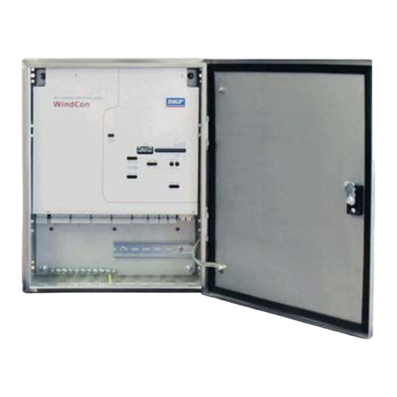
There are two different types of cabinet for IMx-W, WindCon unit; Painted steel cabinet and Stainless steel cabinet. The type of cabinet is chosen by the customer upon purchasing of the unit. Refer to IMx-W, WindCon Drawings for the drawing of cabinets. -
Page 8: Led Indicators
• When the buffer gets full, the oldest data is thrown away. LED Indicators The IMx-W, WindCon card has two rows of LED indicators on the front panel as shown below: Figure 1 - 3. LED Indicators on the Front Panel. - Page 9 In addition, the red LED ALR (alarm) will also light up. However, this only works after the IMx-W, WindCon has been configured and collected some data for measurements, because only then alarms can be checked according to the alarm and danger levels.
- Page 10 RS485, RS232 and CAN LEDs are not in use. Digital In 1 and Digital In 2 indicate the status of digital inputs. On indicates logical one (1) and off indicates logical zero (0). Whereas, flash indicates input toggle. 1 - 6 SKF Multilog On-Line System IMx-W User Manual...
-
Page 11: Installation
Figure 2 - 1. IMx-W, WindCon Front Panel Inside of a Cabinet. The installation of a IMx-W, WindCon system must be carried out according to the instructions and advice given in this manual. Any deviation from these directions can be made only after consulting with the SKF IMx-W, WindCon team or personnel from SKF Condition Monitoring Center Luleå. -
Page 12: Safety And Requirements
In all cases, read the instructions carefully and act accordingly. If the IMx-W, WindCon vibration sensors are to be mounted with glued pads, the temperature must be observed. The glue used for these pads, or studs will not solidify below 16 ºC (60.8 ºF). -
Page 13: Vibration Sensor Cable
CAT5 Ethernet and vice versa. When SKF supplies the GPRS router, it makes use of a "lifeline" connection to an SKF server at IP: 80.126.94.126. This is an integral part of the application solution. -
Page 14: Cable Glands
See Cable Glands section as well. Cable Glands The shield of IMx-W, WindCon sensor cable should be cut off at the entrance of the cabinet and be shielded off from the cabinet by an isolating cable gland. - Page 15 Important - For permanently connected IMx-W an external all pole power switch must be installed in order to be able to disconnect the IMx-W from the mains power grid. The switch must be labeled "IMx-W” or similar. On/Off position must be clearly marked.
-
Page 16: External Mains Out
Important - All externally provided equipment must be evaluated individually and approved together with IMx-W unit regarding EMC and safety requirements (CE and ETL). Always consult SKF CMC Luleå before the usage of the external mains output. In order to attach power cable to the external equipment via the external mains out connector, follow the direction below. - Page 17 Important - External mains out must be connected according to the above information to avoid causing harm to equipment or personnel. Important - External mains output must be carefully used to secure lightning protection. SKF Multilog On-Line System IMx-W 2 - 7 User Manual...
-
Page 18: Communication Cable
Ethernet The Ethernet TP cable on the IMx-W, WindCon is connected at one of the standard Ethernet RJ45 connections. Both Ethernet ports have auto detection of crossover or straight through Ethernet cable connection. Basically, IMx-W, WindCon has a built-in Ethernet switch. - Page 19 Yellow LED Ethernet traffic indicator Green LED Ethernet link indicator Refer to the tables in Wire Connections and the drawing of Connectors and Switches Location for connectors naming and location details. SKF Multilog On-Line System IMx-W 2 - 9 User Manual...
-
Page 21: Unit Configuration
Unit Configuration Mount the IMx-W, WindCon unit and make sure that it is firmly attached. The IMx-W, WindCon unit should be mounted at a location where it is not exposed to unnecessary radiant heat or strong magnetic fields. Always use the supplied mounting brackets, that are easily mounted onto the back side of the IMx-W, WindCon cabinet. -
Page 22: Analogue In 1 To 16 And Analogue Isolated 15, 16
Location of Vibration Sensors On a typical turbine with two main bearings, a planetary gear, a three-shaft second stage gear and a generator, SKF proposes the use of nine accelerometers, four low speeds and five standards. Figure 3 - 1. - Page 23 Important - It is not always necessary to install two tacho sensors. However, it is preferable to install two tacho sensors on the high speed shaft. If Order tracking is used, the tacho sensors must be installed on the high speed shaft. SKF Multilog On-Line System IMx-W 3 - 3 User Manual...
- Page 24 Carefully test-screw the sensor in place, to ensure that good contact has been made. Important - If the sensor does not fit flat on the surface, and thereby makes a bad contact with it, you must drill a new hole. 3 - 4 SKF Multilog On-Line System IMx-W User Manual...
- Page 25 Tightening too hard, besides damaging the thread, causes stress that in return causes signal noises. The correct tightening torque is 3 to 7 Nm. SKF Multilog On-Line System IMx-W 3 - 5 User Manual...
- Page 26 Examples of Attachment by Glue. Connection of Accelerometer Sensor Cables To connect accelerometer sensor cables to IMx-W, WindCon units, you need to use two-wired sensors. IMx-W, WindCon supports both external powered accelerometers and standard accelerometers. The standard accelerometer power is turned on/off in software configuration.
- Page 27 Figure 3 - 4. Connection of Accelerometer Sensor Cables. Note that the sensor shield should be connected either to the sensor or to the IMx-W unit depending on the cable and the sensor type, but NOT to both. Configuration of Analogue/Isolated Inputs Analogue inputs 15 and 16 have the functionality to act as an ordinary analogue input 15 and 16 or act as analogue isolated input 15 and 16.
- Page 28 The jumpers are located behind the front panel which has to be removed in order to adjust them. Refer to the tables in Wire Connections and the drawing of Connectors and Switches Location for connectors naming and location details. 3 - 8 SKF Multilog On-Line System IMx-W User Manual...
- Page 29 When sensor is in position, close the loop firmly and secure with the locknut. Important - Remember to place the power sensor around only one of the generator phase cables. Figure 3 - 5. Flexible Load Sensor. SKF Multilog On-Line System IMx-W 3 - 9 User Manual...
- Page 30 1 - Coax center signal conductor (signal +) 2 - Coax signal shield (signal –) GND - Should be connected to IMx-W, WindCon power ground strip, since the sensor is fully isolated (10 kV peak). Important - The flexible sensor GND wire should be connected to IMx-W power ground to prevent signal noise.
- Page 31 However, as we mentioned before, the usage of it is for indicating power and to trigger measurements, it is sufficient enough. The values can manually be finely tuned, but the following example description of sensitivity is often a good enough approximation for triggering measurements. SKF Multilog On-Line System IMx-W 3 - 11 User Manual...
- Page 32 Change xxxx [kW] to the maximum power of the generator in kilo watt (kW) for example 1,5 MW turbine = 1 500 kW. • yy,yy [mV] is the output of the sensor when the generator is producing maximum power. 3 - 12 SKF Multilog On-Line System IMx-W User Manual...
- Page 33 ) / 1,4142 = 17,9 mV peak Hence yy,yy = 17,9 [mV] xxxx = 1 500 [kW] Put the two values from above into each field and click on calculate button and sensitivity will be calculated. SKF Multilog On-Line System IMx-W 3 - 13 User Manual...
- Page 34 Figure 3 - 9. Create a Process FFT Measurement Point. Step 3 - Configure general settings of the process FFT measurement point. Figure 3 - 10. General Settings of Process FFT Measurement Point. 3 - 14 SKF Multilog On-Line System IMx-W User Manual...
- Page 35 Spectra Settings of Process FFT Measurement Point. Step 5 - Configure trend settings of the process FFT measurement point. Figure 3 - 12. Trend Settings of Process FFT Measurement Point. SKF Multilog On-Line System IMx-W 3 - 15 User Manual...
- Page 36 • Click on the right mouse button, select Add, then Point • Select IMx, then Derived point. Figure 3 - 14. Create a Derived Measurement Point. 3 - 16 SKF Multilog On-Line System IMx-W User Manual...
- Page 37 Step 9 - Configure general settings of the derived measurement point. Functions must have the same names as the names of the parameters you have added. Figure 3 - 16. General Settings of Derived Measurement Point. SKF Multilog On-Line System IMx-W 3 - 17 User Manual...
- Page 38 Observer to match 2 MW (in this case, you need to increase the values by 25%). This can happen because of mounting and cable losses occurring at the installation. 3 - 18 SKF Multilog On-Line System IMx-W User Manual...
-
Page 39: Digital/Tacho
Figure 3 - 18. Connection of Pulse Transmitter. A pulse transmitter (tacho), linked to IMx-W, WindCon, is used to measure rotational speed of the main shaft. The tacho could be mounted to detect holes (lack of metal) or something sticking out, like a bolt head (metal). The distance between sensor and the measurement object should be adjusted to 2 to 4 mm when the lack of metal is to be sensed. - Page 40 Mounting Instruction Guidelines. Connection of Tacho Cables In order to connect the tacho cables to IMx-W, WindCon units, both two- and three- wire tacho sensors are supported. They are two-wired, three-wired NPN, three-wired PNP, pulse source TTL and pulse source 12 V. The sensor input terminals and the DIP switches that are used to configure the inputs, are shown in the following diagrams.
- Page 41 Unit Configuration Digital/Tacho Figure 3 - 21. Tacho Three-wire NPN. Figure 3 - 22. Tacho Three-wire PNP. SKF Multilog On-Line System IMx-W 3 - 21 User Manual...
- Page 42 Unit Configuration Digital/Tacho Figure 3 - 23. Tacho Pulse Source (12 V). Figure 3 - 24. Tacho Pulse Source (TTL). 3 - 22 SKF Multilog On-Line System IMx-W User Manual...
-
Page 43: Relay Drivers
Location for connectors naming and location details. Relay Drivers IMx-W, WindCon has two relay driver outputs that can be connected to a relay as shown below. For both outputs in total, +12 V power is allowed for the maximum current of 300 mA. - Page 44 Note that terminals DO_Ch1 +12V and DO_Ch2 +12V always have the voltage +12V, whereas terminals DO_Ch1 and DO_Ch2 are low side drivers known as open collectors. Figure 3 - 26. Relay Open Collector Driver Showing Alarm Inactive. 3 - 24 SKF Multilog On-Line System IMx-W User Manual...
-
Page 45: Can-Bus
CAN-bus is a high speed serial interface used for interconnecting different systems to IMx-W, WindCon , such as SKF Vogel lubrication systems. If IMx-W, WindCon unit is placed first or last in the CAN-bus chain, then the built-in CAN-bus termination in the IMx-W, WindCon unit must be activated. -
Page 46: Rs485/Modbus
RS485/Modbus is used to transfer measurement data from other systems to the IMx- W, WindCon unit. If the IMx-W, WindCon unit is placed first or last in the RS485 bus chain, then the built-in RS485 bus termination in the IMx-W, WindCon unit must be activated. -
Page 47: Network Configuration
Observer Monitor Service to which it should be connected. Keep in mind that most of the time, all IMx-W, WindCon units are on the same network and database, therefore units can NOT have a same IP address or a same unit ID. - Page 48 RS232 interface is used only when the required basic network configuration setup is being done. The RS232 connector is located on the front panel of the IMx-W, labeled as DSUB1. See Connectors and Switches Location in IMx-W, WindCon Drawings chapter for the physical location.
-
Page 49: Network Load
The IMx-W, WindCon system is permanently monitoring, always measuring and collecting data from all the sensors. The IMx-W, WindCon is connected to the @ptitude Observer Monitor Service by on-line, and data is stored in the database as a separate process from the continuous measuring cycle. -
Page 50: Imx-W Time
= 11,3 MB/month (average of 30 days per month) IMx-W Time IMx-W unit has a backup power capacitor which will keep the time for at least a month if IMx-W is disconnected from a power inlet. To correct or set IMx-W time, use one of the following methods. -
Page 51: Hardware Maintenance
The IMx-W, WindCon hardware, i.e. IMx-W, WindCon and the sensors are virtually maintenance free, however we advise the customer to do a yearly visual inspection of the equipment. Performance over Time There is no significant performance degradation to be expected over time for IMx-W, WindCon hardware. Dismantling IMx-W Summary •... - Page 52 Figure 4 - 3. Locations of 4 Mounting Screws on Front Panel. 4. Lift the front panel and remove it as shown below. Figure 4 - 4. Lift the Front Panel and Remove. 4 - 2 SKF Multilog On-Line System IMx-W User Manual...
- Page 53 5. Identify the three main components; The PSU (Power Supply), the CPU Board and the Lightning protection board as shown below. Figure 4 - 5. Three Main Components in IMx-W. SKF Multilog On-Line System IMx-W 4 - 3 User Manual...
- Page 54 7. All work on the boards from now on must be performed wearing an ESD wrist strap with galvanic contact to the steel cabinet as shown below. Figure 4 - 7. Always Use an ESD Write Strap When Handling the Lightning Protection Board. 4 - 4 SKF Multilog On-Line System IMx-W User Manual...
- Page 55 Hardware Maintenance Dismantling IMx-W 8. The Lightning Protection Board is separated from the IMx-W by disconnecting two power supply connectors and unscrewing nine bolts. Figure 4 - 8. Disconnect Power Supply Contacts (blue arrows) and Remove Screws (black arrows). 9. Then, pull the Lightning Protection Board down in the direction of the arrows as shown below to disconnect it from the CPU board.
-
Page 56: Assembling Imx-W
Figure 4 - 10. Remove Screws to Detach Power Supply and CPU Board. Assembling IMx-W The IMx-W is assembled by performing steps 1 to 10 in Dismantling IMX-W in reverse order. After assembling IMx-W, the Installation and Unit Configuration must be performed accordingly in order to ensure the proper functioning of the IMx-W. - Page 57 Replacing a Burnt Fuse in IMx-W Figure 4 - 11. Location of Fuses (F1, F2) in IMx-W. 3. Replace the burnt fuse with a slow blow 2A (T2A 250 V, 5 x 20 mm) fuse. Refer to Mains Power for more detailed information on mains power and power cable attachment.
- Page 59 Electrical waste and electrical equipment should be recycled according to the WEEE- directive and not be placed in the general refuse. Product should be sent to an approved recycling center for safe recycling, recovery, reuse or sent to SKF Condition Monitoring Center AB for proper recycling.
-
Page 61: Technical Data
Software controlled power supply for standard accelerometers (4 mA constant current) for each individual channel • Simultaneous measurement of all channels • Input range ±25 V • Impedance >100 kΩ SKF Multilog On-Line System IMx-W 6 - 1 User Manual... -
Page 62: Digital Inputs
Required pulse width: > 4 µs for electrical positive, > 40 µs for electrical negative • Accuracy frequency: 0,05% of measurement value (typically 0,01% up to 2,5 kHz) • Pulse counting 6 - 2 SKF Multilog On-Line System IMx-W User Manual... -
Page 63: Signal Processing
CAN-bus interface for data sharing with other systems • RS485 (Modbus) interface for data sharing with other systems Data Processing • 64 MB RAM for data processing (from serial number >=12000) SKF Multilog On-Line System IMx-W 6 - 3 User Manual... -
Page 64: Miscellaneous
Lightning protection: EN 61000-4-5, ±4 kV line-earth, ±2 kV line-line, ±4 kV signal • Support IEC 61850 • GL certified Quality Control SKF Condition Monitoring Center Luleå is ISO 9001:2008 certified. 6 - 4 SKF Multilog On-Line System IMx-W User Manual... -
Page 65: Troubleshooting Guide
Troubleshooting Guide Troubleshooting Guide is intended as an aid when IMx-W system is not functioning correctly. It is designed for instrumentation engineers and others with sufficient knowledge of electrical troubleshooting in electronic systems with a 230 V/110 V power supply and of the risks that this can mean in case of incorrect procedure. - Page 66 Incorrect setting in software Suggested solution: • The load input acts as an analogue input. Therefore, first carry out cabling/input test. Contact SKF Condition Monitoring Center Luleå if this gives no result. 7 - 2 SKF Multilog On-Line System IMx-W User Manual...
- Page 67 Hardware fault in IMx-W unit, such as power supply or processor module • Break in Ethernet network Suggested solution: • Check the voltage of IMx-W unit. In addition, check the Ethernet built-in LED indicator behavior. Monitor completely ceases to function Possible causes: •...
-
Page 68: Component Check
NO: Continue to step 5. 4. Does the fault remain after changing the sensor? YES: The fault may be in the analogue input section of the IMx-W unit. Contact SKF Condition Monitoring Center Luleå for service and further information. NO: Sensor fault. The sensor is defective and must be replaced. - Page 69 Component Check 7. Is the sensor a standard type? YES: These are powered internally from the IMx-W unit. If the IMx-W unit does not supply open circuit voltage with input open, then the IMx-W input is probably damaged, or the input is not configured to supply a power feed to the sensor.
- Page 70 6. Cable is probably damaged. However, first try disconnecting one of the poles on the cable from the IMx-W terminal block. If the voltage is Ok, then the fault is in the IMx-W unit input stage. Otherwise, the cable is damaged and needs to be repaired.
- Page 71 3. Is there an expected speed signal on the IMx-W terminal block? YES: The signal can be too weak or at too high impedance for the IMx-W speed input to be triggered. Sufficient voltage ripple (peak to peak) is shown in the electrical specifications.
- Page 72 The Modbus Master-Slave pair address is entered correctly 7. This process of checking Modbus sensor can be done several times during the test to diagnose the communications or lack of it. 7 - 8 SKF Multilog On-Line System IMx-W User Manual...
-
Page 73: Summary
Hex_A (x 10) Hex_B (x 1) Software defined ↓ ↓ ↓ Factory default configuration TCP/IP address: 10.0.0.1XY Table 8-2: Summary of IMx-W, WindCon DIP switches and jumper settings. Switch Switch Description DIP1 Digital input 1 DIP2 Digital input 2 DIP3... - Page 74 DIP2 is used to configure digital input 2 channel. Table 8-7: CAN-bus termination settings. CAN Termination DIP4 No termination 0000 Termination (default) 1000 Table 8-8: RS485 bus termination settings. RS485 Termination DIP3 No termination 0000 Termination (default) 1000 8 - 2 SKF Multilog On-Line System IMx-W User Manual...
-
Page 75: Led Status
Not in use DigIn1, DigIn2 Input logic one Input logic zero Flash Input toggle Wire Connections Table 8-10: Wire connections for external mains out. External mains out Description PE (protective earth) SKF Multilog On-Line System IMx-W 8 - 3 User Manual... - Page 76 Analogue in Ch9 (+) Analogue in Ch9 (–) Analogue in Ch10 (+) Analogue in Ch10 (–) Analogue in Ch11 (+) Analogue in Ch11 (–) Analogue in Ch12 (+) Analogue in Ch12 (–) 8 - 4 SKF Multilog On-Line System IMx-W User Manual...
- Page 77 Relay driver 1 and 2 Description Digital out Ch1 Digital out Ch1 (+12 V) Digital out Ch2 (+12 V) Digital out Ch2 Table 8-18: Wire connections for CAN. Description CAN_H CAN_L SKF Multilog On-Line System IMx-W 8 - 5 User Manual...
- Page 78 Ethernet link indicator Table 8-21: RS232 connector pinout. RS232 Connector Pintout Description N.C. (Not Connected) N.C. (Not Connected) N.C. (Not Connected) N.C. (Not Connected) N.C. (Not Connected) N.C. (Not Connected) 8 - 6 SKF Multilog On-Line System IMx-W User Manual...
-
Page 79: Imx-W, Windcon Drawings
IMx-W, WindCon Drawings Stainless Steel Cabinet Drawings Stainless Steel Cabinet Figure 9 - 1. Stainless Steel Cabinet Drawing with Mounting Brackets. SKF Multilog On-Line System IMx-W 9 - 1 User Manual... - Page 80 IMx-W, WindCon Drawings Stainless Steel Cabinet Drawings Stainless Steel Cabinet Mounting Bracket Figure 9 - 2. Stainless Steel Cabinet Mounting Bracket. 9 - 2 SKF Multilog On-Line System IMx-W User Manual...
- Page 81 IMx-W, WindCon Drawings Stainless Steel Cabinet Drawings Stainless Steel Cabinet Bottom Holes Figure 9 - 3. Stainless Steel Cabinet Bottom Holes. SKF Multilog On-Line System IMx-W 9 - 3 User Manual...
-
Page 82: Painted Steel Cabinet Drawings
IMx-W, WindCon Drawings Painted Steel Cabinet Drawings Painted Steel Cabinet Drawings Painted Steel Cabinet Figure 9 - 4. Painted Steel Cabinet Drawing with Mounting Brackets. 9 - 4 SKF Multilog On-Line System IMx-W User Manual... - Page 83 IMx-W, WindCon Drawings Painted Steel Cabinet Drawings Painted Steel Cabinet Mounting Bracket Figure 9 - 5. Painted Steel Cabinet Mounting Bracket. SKF Multilog On-Line System IMx-W 9 - 5 User Manual...
- Page 84 IMx-W, WindCon Drawings Painted Steel Cabinet Drawings Painted Steel Cabinet Bottom Holes Figure 9 - 6. Painted Steel Cabinet Bottom Holes. 9 - 6 SKF Multilog On-Line System IMx-W User Manual...
-
Page 85: Connectors And Switches Location
IMx-W, WindCon Drawings Connectors and Switches Location Connectors and Switches Location Figure 9 - 7. Connectors and Switches Location. SKF Multilog On-Line System IMx-W 9 - 7 User Manual... -
Page 87: Limited Warranty
Shaft provided, however, that SKF shall not be liable Alignment Systems TKSA 60 and TKSA 80 for any claim for which notice is received by SKF including hand-held computer, measuring units more than thirty (30) days following the and accessories. - Page 88 Products warranted for five (5) years by SKF are months from the date the On-line System is as follows: special seismic sensors. shipped by SKF to Buyer, two (2) years from the date the On-line System is installed and LIMITED LIFETIME WARRANTY...
- Page 89 Lifetime Warranty are set forth in hereunder and if requested or authorized in paragraphs (A) and (B), and SKF’s liability writing by SKF, Buyer shall forward to SKF any under this Limited Lifetime Warranty Product claimed by Buyer as being defective.
- Page 90 EXCEPT WARRANTY OF TITLE AND FOR THE warranty shall not be deemed to have failed of WARRANTIES EXPRESSLY SET FORTH IN their essential purpose so long as SKF is willing HEREIN, IT IS UNDERSTOOD AND AGREED and able to perform to the extent and in the THAT: manner prescribed in this limited warranty.
- Page 91 On-line Device Configurator 3-27 fuse holder 2-4 outputs 6-2 GPRS router 2-2 pollution degree 6-1 port number 3-27 power cable 2-4 power consumption 6-1 hardware maintenance 4-1 power supply 6-1, 6-2 help 7-1 SKF Multilog On-Line System IMx-W Index - 1 User Manual...
- Page 92 2-3 set time 3-30 signal processing 6-3 signal to noise ratio 6-2 simultaneous sampling 6-2 SKF @ptitude Analyst IMx Service 1-2 SKF @ptitude Observer Monitor Service 1-2 SKF Multilog On-line System 1-2 special care 1-1 supply cable 2-3...
Need help?
Do you have a question about the IMx-W and is the answer not in the manual?
Questions and answers