Table of Contents
Advertisement
Quick Links
SKF Multilog On-line
System IMx-Rail
User Manual Supplement
Part Number 15V-090-00082-100
Revision B – September 2020
Read this manual carefully before using the product. Failure
to follow the instructions and safety precautions in this manual can
result in serious injury, damage to the product or incorrect
readings. Keep this manual in a safe location for future reference.
Copyright © 2018 by SKF Group
All rights reserved.
SKF Sverige AB
Aurorum 30, 977 75 Luleå, Sweden
Telephone: +46 (0) 31 337 10 00
Advertisement
Table of Contents

Related Manuals for SKF IMx-Rail


Summary of Contents for SKF IMx-Rail
- Page 1 Keep this manual in a safe location for future reference. Copyright © 2018 by SKF Group All rights reserved. SKF Sverige AB Aurorum 30, 977 75 Luleå, Sweden...
- Page 3 SKF reserves the right to alter any part of this publication without prior notice. Patents: US , •...
- Page 4 – SKF's Technical Support Group can be reached during normal business hours Technical Support via phone, e-mail and live chat. Always check the self-service web portal before contacting your nearest Technical Support Group (TSG) to see if the answer is already published. You may search...
-
Page 5: Table Of Contents
Table of contents Product description ............... 7 Introduction to the SKF Multilog On-line System IMx-Rail ......7 SKF Multilog On-line System IMx-16Plus ............8 1.2.1 LTE/GSM (mobile) data module ............8 1.2.2 Local network RJ45 or Wi-Fi module ..........8 1.2.3... - Page 6 3.3.11 Data processing memory ............... 21 3.3.12 Certifications .................. 21 3.3.13 Quality control ................21 Connector details for SKF Multilog IMx-Rail ..........22 3.4.1 IMx-Rail ..................22 3.4.2 IMx-16Plus top end cap ..............23 3.4.3 IMx-16Plus bottom end cap ............23 Enclosure mechanical drawings ..............
-
Page 7: Product Description
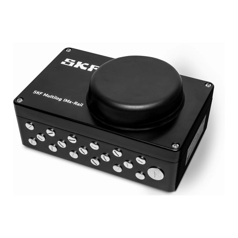
1.1 Introduction to the SKF Multilog On-line System IMx-Rail The SKF Multilog On-line System IMx-Rail is an online condition monitoring system specifically designed for railway applications and consisting of a 16-channel monitoring device complete with mobile and LAN data interfaces (IMx-16Plus), pre- installed in an outer protective enclosure. -
Page 8: Skf Multilog On-Line System Imx-16Plus
Installation and operating instructions. In an IMx-Rail device, it is supplied pre-fitted in the Rail enclosure and pre-wired to the lid mounted antenna and to easily accessible user terminals, above the unit. These encompass all the terminals available on the IMx-16Plus itself, such as analogue inputs, digital I/O and RS485. -
Page 9: Modbus Interfacing To External Systems
The IMx-Rail is designed to be mounted on either the train bogie, train car chassis or internally in a car/coach as appropriate to the equipment and bearings being monitored. -
Page 10: Installation And Operating Instructions
2 Installation and operating instructions 2.1 Introduction At the heart of the IMx-Rail is an IMx-16Plus. This is an updated version of the ‘IMx- 8’ with additional sensor capacity (increased number and wider range of sensor types) and with the additional interfaces needed for rail applications such as GPS, mobile data and Wi-Fi. -
Page 11: System Communications
IMx-Rail: • Server initiated (@ptitude Observer initiated communication) • Client-Server (the IMx-Rail is the initiator of the communication) These are alternatives for @ptitude Observer/IMx communication, illustrated diagrammatically in Figure 2. Whilst in general, the different network connection possibilities (1.2.1... -
Page 12: Power Requirements
Nominal supply voltages between 24 and 110 V DC are accommodated by appropriate choice of IMx-Rail model (nominal 24 V DC or 110 V DC input). The supply to the IMx-Rail device should be protected by an appropriately rated fuse, refer 3.3.2. -
Page 13: On Train Cabling
IMx-Rail, to train systems. Make sure that the power is disconnected before the installation begins. To connect the IMx-Rail to the DC power supply, use cable of the following standard or better: FKLK 3 x 1.5 mm2 (16 AWG) or EKLK 3 x 1.5 mm2 (16 AWG) or corresponding, with minimum voltage requirement 300 V and temperature range of −40 to... -
Page 14: Cable Glanding
The glands used with the IMx-Rail should be chosen to maintain the enclosure IP rating and be appropriate for a railway environment and the cable type. As mentioned above, 2.5, the IMx-Rail is prepared for a mix of M12 x 1.5mm and M20 x 1.5mm glands. -
Page 15: Gps Module Connection Notes
Amber flashing: Modbus communications activity 2.6.2 RS485 Modbus bus termination If an IMx-Rail device is placed first or last in the bus chain, then an external bus termination resistor must usually be connected to it. (Note: there is no built-in termination that can be activated by configuration). -
Page 16: Commissioning And Maintenance
16Plus User Manual, for guidance on checks that can be made and where necessary contact SKF TSG for advice. Any repairs to an IMx-Rail device should only be carried by an SKF repair centre. They can source all required replacement parts, including the... -
Page 17: Product Specifications
Manufacturing data label 24 V version Figure 4 Manufacturing data label 110 V version Refer to 3.3.12 (detailed product specifications) for a complete listing of compliances and certifications. SKF Multilog On-line System IMx-Rail 17 (29) User Manual Supplement Revision B... -
Page 18: Eu Declaration Of Conformity
PRODUCT SPECIFICATIONS EU Declaration of Conformity 3.2 EU Declaration of Conformity 18 (29) SKF Multilog On-line System IMx-Rail User Manual Supplement Revision B... -
Page 19: Skf Multilog On-Line System Imx-Rail
PRODUCT SPECIFICATIONS SKF Multilog On-line System IMx-Rail 3.3 SKF Multilog On-line System IMx-Rail 3.3.1 Environmental • Size (H x W x D): 260 x 160 x 90 mm (10.24 x 6.30 x 3.54 in.) Dimensions do not include antenna and glands/cable exits... -
Page 20: Analogue Inputs
PRODUCT SPECIFICATIONS SKF Multilog On-line System IMx-Rail Aluminium cased Isolated (input/output, input/case) Continuous short circuit protection with automatic recovery 3.3.3 Analogue inputs • 16 analogue single ended inputs, referenced to chassis/enclosure ground. • Channels 9 to 16 can connect to additional sensor types PT1000, temperature probes (2-wire connection) •... -
Page 21: Storage Capacity
PRODUCT SPECIFICATIONS SKF Multilog On-line System IMx-Rail • The lid mounted antenna / IMx-Rail combination supports the following frequencies and standards: AMPS 850 MHz GSM 900 MHz 3G UMTS 2.1 GHz Wi-Fi 2.4 GHz DCS 1800 MHz PCS 1900 MHz LTE 2.6 GHz... -
Page 22: Connector Details For Skf Multilog Imx-Rail
PRODUCT SPECIFICATIONS Connector details for SKF Multilog IMx-Rail 3.4 Connector details for SKF Multilog IMx-Rail 3.4.1 IMx-Rail Table 3 IMx-Rail user connection terminals Terminal Description Digital1-4 4 digital inputs (Ground, Signal, Power terminals for each) CAN L/N CAN bus for vehicle systems (Currently no firmware support) -
Page 23: Imx-16Plus Top End Cap
Note that (as shown), in the IMx-Rail the IMx-16Plus is mounted ’upside down’. That is: the top end cap is at the power connector end of the IMx-Rail, but the DC input to the IMx-16Plus is away from that connector. Be aware of that orientation when locating the RJ45 connector, SIM card slot etc. -
Page 24: Enclosure Mechanical Drawings
Enclosure mechanical drawings 3.5 Enclosure mechanical drawings The SKF Multilog IMx-Rail is housed in a (black) powder coated, die cast aluminium enclosure. It has overall dimensions of 260 mm long, 160 mm wide (excluding glands, cabling and connector) and is 90 mm deep with fixing centres of 238 x 111... - Page 25 Figure 6 The main wall gland area is for the majority of the user wiring (sensors etc.). IMx-Rail enclosure pre-drilling – back long wall, 3 positions (1 connector in red) Figure 7 The back-wall has three cable entries and the input power connector. This wall of the...
-
Page 26: Gps Module Mechanical Drawings
Figure 8 3.6 GPS module mechanical drawings The GPS module, CMON 4139, is connected to the IMx-Rail via a 5-m integral cable and should be fitted externally to the enclosure in a location that allows satellite tracking. An M12 cable gland is included. -
Page 27: Electrical Waste
Electrical waste and electrical equipment should be recycled as specified by the WEEE-directive and not be placed in the general refuse. Product should be sent to an approved recycling centre for safe recycling, recovery, reuse or sent to SKF Sverige AB for proper recycling. SKF Sverige AB Aurorum 30 977 75 Luleå... -
Page 29: Appendix A Limited Warranty
APPENDIX A Limited Warranty Appendix A Limited Warranty SKF – Limited Warranty Download the latest version from skf.com. SKF Multilog On-line System IMx-Rail 29 (29) User Manual Supplement Revision B...
Need help?
Do you have a question about the IMx-Rail and is the answer not in the manual?
Questions and answers