Table of Contents
Advertisement
Quick Links
SKF Multilog On-Line
System IMx-S
User Manual Part No. 32087700-EN
Revision R
WARNING! Read this manual before using this product. Failure to follow the
instructions and safety precautions in this manual can result in serious injury, damage
to the product, or incorrect readings. Keep this manual in a safe location for future
reference.
Copyright 2016 by SKF Group
All rights reserved.
SKF Condition Monitoring Center – Luleå
Aurorum 30, 977 75 Luleå, Sweden
Telephone: +46 (0) 31 337 10 00, Fax: +46 (0) 920 134 40
User manual
Advertisement
Table of Contents

Subscribe to Our Youtube Channel
Related Manuals for SKF Multilog IMx-S Series


Summary of Contents for SKF Multilog IMx-S Series
- Page 1 Keep this manual in a safe location for future reference. Copyright 2016 by SKF Group All rights reserved. SKF Condition Monitoring Center – Luleå...
- Page 2 SKF reserves the right to alter any part of this publication without prior notice.
-
Page 3: Table Of Contents
Network Configuration ..........3-8 IMx-S Time..............3-10 Hardware Maintenance Electrical Waste Troubleshooting Guide Problems and Symptoms ......... 6-1 Component Check ............6-3 Technical Data Environmental ............7-1 Power Supply .............. 7-1 SKF Multilog On-Line System IMx-S TOC - 1 User Manual... - Page 4 IMx-S Drawings IMx-S 16 Standard Cabinet ........8-1 IMx-S 16 Stainless Steel Cabinet ......8-2 IMx-S 32 Standard & Stainless Steel Cabinet ..8-3 Terminal List ............... 8-4 Limited Warranty Index TOC - 2 SKF Multilog On-Line System IMx-S User Manual...
-
Page 5: Introduction
The switch must be located close to the IMx-S, within operator's easy reach. IMx-S unit contains circuit boards that are static sensitive. Therefore, use appropriate precautions to prevent ElectroStatic Discharge (ESD) when handling circuit boards. SKF Multilog On-Line System IMx-S 1 - 1 User Manual... -
Page 6: System Overview
The picture above illustrates how IMx-S units are linked together in a network that is connected via a LAN (it may also be a modem or GPRS router) to a SKF @ptitude Observer Monitor or Analyst IMx Service. The @ptitude Observer Monitor or Analyst IMx Service in turn can be connected to e.g. -
Page 7: Imx-S Unit
It is also possible to connect different types of on-line units in the same network, for example, IMx-S together with other IMx units and/or MasCon systems. IMx-S Unit Figure 1 - 2. SKF Multilog On-line System IMx-S 16 (left) and IMx-S 32 (right). IMx-S 16 • Up to 16 analogue channels •... -
Page 8: System Led Indicators
Note that SYS LED is on for a short time when the system is cold booted or re-started. • Green LED PWR indicates the status of power. On means that the power is Ok. 1 - 4 SKF Multilog On-Line System IMx-S User Manual... -
Page 9: Installation
Therefore, contact the IMx-S application engineer at the slightest doubt during the installation. Installation errors which require the involvement of SKF Condition Monitoring Center Luleå personnel in order to rectify the start of the system, might be debited. -
Page 10: Scenario
GPRS forms a part of the customers internal IP network (VPN). In such case, SKF must be informed of this before ordering the GPRS, so that SKF can disable the lifeline functionality of the GPRS router. -
Page 11: Supply Cable
Touching the leads of a powered cable can cause serious injuries. Important - In some countries, you have to be certified in order to connect an IMx- S to the power grid. SKF Multilog On-Line System IMx-S 2 - 3 User Manual... - Page 12 Important - All externally provided equipment must be evaluated individually and approved together with IMx-S unit regarding EMC and safety requirements (CE and ETL). Always consult SKF CMC Luleå before the usage of the external mains output. 2 - 4...
-
Page 13: Communication Cable
Yellow LED is the Ethernet traffic indicator which flickers whenever there is traffic on the network. • Green LED is the Ethernet link indicator which lights up when the system is correctly connected to another network device. SKF Multilog On-Line System IMx-S 2 - 5 User Manual... -
Page 15: Unit Configuration
Figure 3 - 1. IMx-S Terminal Connection, Standard Accelerometer. The IMx-S I/O board along with the corresponding analogue terminal list are shown below. SKF Multilog On-Line System IMx-S 3 - 1 User Manual... - Page 16 100100 sensor (max 35 mA) Signal Com. 4–20 mA (IMx + Signal 100101 powered) – Signal N.C. N.C. = Not Connected DIP switch setting 1 = ON, 0 = OFF 3 - 2 SKF Multilog On-Line System IMx-S User Manual...
-
Page 17: Digital Inputs
IMx-S 16 10 W IMx-S 32 10 W (at 60 ˚C [140 °F] only ICP sensors are recommended) At lower temperatures more total sensor power is allowed; please contact SKF Condition Monitoring Center Luleå or application engineer. Important - Do NOT change DIP switch settings while the IMx-S unit is powered- up, as this may cause damage and void warranty. - Page 18 They are only used for externally powered signals with signal level of 12 to 24 V, square wave signal. Table 3-6: Digital inputs 5 to 8 terminal list. Signal Terminal Pulse 12–24 V (external power) – 3 - 4 SKF Multilog On-Line System IMx-S User Manual...
-
Page 19: Rs485 Communication
Modbus protocol is used for RS485 communication. IMx-S can be configured as master or slave. However, if IMx-S is configured as master, only one slave device will be supported. If more than one slave device is needed, contact SKF Condition Monitoring Center, Luleå. -
Page 20: Relays
Relay Driver Output Connections. Note that terminals Dig +12V always have the voltage +12 V, whereas terminals Dig1 OUT to Dig4 OUT are low side drivers known as open collectors. 3 - 6 SKF Multilog On-Line System IMx-S User Manual... - Page 21 The phase of the buffered output has been inverted on I/O board v1.24 and greater (with a hole in front panel for DIP21). (The inverted buffered out will have the same phase as connected to an IMx 2-wire input!) SKF Multilog On-Line System IMx-S 3 - 7 User Manual...
-
Page 22: Network Configuration
Suite. For detailed information, refer to @ptitude Observer On-line Device Configurator User Manual. • For Analyst clients, Multilog IMx Configurator in Admin Tools under SKF @ptitude Monitoring Suite. There are two ways to configure a network and ID configuration: by Software: is configured by the software via On-line Device Configurator or •... - Page 23 Therefore, the cable should not be connected to RS232 connector at any other time. Table 3-11: RS232 connector pinout. RS232 Connector Pinout Description N.C. N.C. N.C. N.C. N.C. N.C. N.C. = Not Connected SKF Multilog On-Line System IMx-S 3 - 9 User Manual...
-
Page 24: Imx-S Time
In @ptitude Observer, the function is found under a tab menu called "On-line", then "MasCon/IMx units" interface. In @ptitude Analyst, the function is found at Transfer / Online / Status. 3 - 10 SKF Multilog On-Line System IMx-S User Manual... -
Page 25: Hardware Maintenance
Hardware Maintenance The IMx-S hardware, i.e. the IMx-S unit is maintenance free. However, we advise the customers to do a yearly visual inspection of the equipment. SKF Multilog On-Line System IMx-S 4 - 1 User Manual... -
Page 27: Electrical Waste
Electrical waste and electrical equipment should be recycled according to the WEEE- directive and not be placed in the general refuse. Product should be sent to an approved recycling center for safe recycling, recovery, reuse or sent to SKF Condition Monitoring Center AB for proper recycling. -
Page 29: Troubleshooting Guide
110 V/230 V power supply and of the risks that this can mean in case of incorrect procedure. SKF Condition Monitoring Center Luleå strives to provide information that is as accurate as possible. However, SKF Condition Monitoring Center Luleå cannot be held responsible for any injury or damage to persons or material that can occur in the interpretation of, or due to actions taken on the basis of information in this document. - Page 30 Suggested solution: • The load input acts as an analogue input. Therefore, first carry out cabling/input test. Contact SKF Condition Monitoring Center Luleå if this gives no result. IMx-S alarm relay does not activate despite of warning or alarm Possible causes: •...
-
Page 31: Component Check
Normal voltage. Table 6-1: Sensor type Normal operating bias Open circuit voltage (DC voltage (DC V) Standard accelerometer 8 to 12 V +24 V SKF Multilog On-Line System IMx-S 6 - 3 User Manual... - Page 32 4. Does the fault remain after changing the sensor? YES: The fault may be in the analogue input section of the IMx-S unit. Contact SKF Condition Monitoring Center Luleå for service and further information. NO: Sensor fault. The sensor is defective and must be replaced.
- Page 33 Determine the amplification, zero level, and the conversion to the user’s unit. Furthermore, the cable check must be off (N). If this still does not produce the correct actual value, then the input card is probably damaged. Contact SKF Condition Monitoring Center Luleå.
- Page 34 7. Does the fault remain after replacing the sensor? YES: The fault can be in the analogue input part of the IMx-S unit. Contact SKF Condition Monitoring Center Luleå. NO: It is a sensor fault. Replace the sensor.
- Page 35 If this is not the case, then change the setting. Contact SKF Condition Monitoring Center Luleå, if the channel is permitted to activate the relay, but does not do Checking monitor 1.
- Page 36 The Modbus Master-Slave pair address is entered correctly RS485 termination is done correctly 7. This process of checking Modbus communication can be done several times during the test to diagnose the communications or lack of it. 6 - 8 SKF Multilog On-Line System IMx-S User Manual...
-
Page 37: Technical Data
Maximum altitude: 2 000 m (6 561.7 ft.) Power Supply • 100 to 240 VAC, 47 to 63 Hz • Power consumption: – IMx-S 16: 30 W – IMx-S 32: 60 W SKF Multilog On-Line System IMx-S 7 - 1 User Manual... -
Page 38: Analogue Inputs
24-bit AD conversion enabling continuous transient capture (no gain or AC/DC switching necessary) • True simultaneous sampling (no multiplexing): – IMx-S 16: all 16 channels – IMx-S 32: all 32 channels 7 - 2 SKF Multilog On-Line System IMx-S User Manual... -
Page 39: Digital Measurement
Data storage on time, event or alarm condition • Data buffering in flash memory when communication link is down • Detection of sensor and cable fault • Watchdog and self testing SKF Multilog On-Line System IMx-S 7 - 3 User Manual... -
Page 40: Interface
64 MB RAM for data processing (from serial number ≥ 12000) Miscellaneous • Calibration, traceable to BIPM • CE certified according to EN61000-6-3 and EN61000-6-2 • Support IEC 61850 Quality Control SKF Condition Monitoring Center, Luleå is ISO 9001:2008 certified. 7 - 4 SKF Multilog On-Line System IMx-S User Manual... -
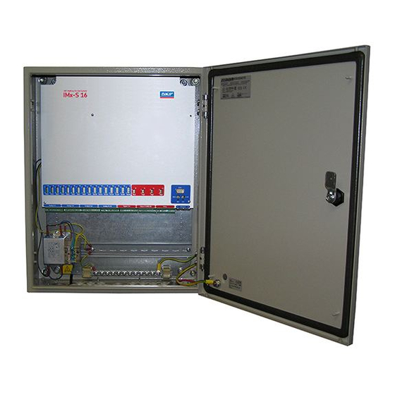
Page 41: Imx-S Drawings
IMx-S Drawings IMx-S 16 Standard Cabinet Figure 8 - 1. IMx-S 16 Standard Cabinet. SKF Multilog On-Line System IMx-S 8 - 1 User Manual... -
Page 42: Imx-S 16 Stainless Steel Cabinet
IMx-S Drawings IMx-S 16 Stainless Steel Cabinet IMx-S 16 Stainless Steel Cabinet Figure 8 - 2. IMx-S 16 Stainless Steel Cabinet. 8 - 2 SKF Multilog On-Line System IMx-S User Manual... -
Page 43: Imx-S 32 Standard & Stainless Steel Cabinet
IMx-S Drawings IMx-S 32 Standard & Stainless Steel Cabinet IMx-S 32 Standard & Stainless Steel Cabinet Figure 8 - 3. IMx-S 32 Standard & Stainless Steel Cabinet. SKF Multilog On-Line System IMx-S 8 - 3 User Manual... -
Page 44: Terminal List
IMx-S Drawings Terminal List Terminal List Table 8-1: Terminal list. 8 - 4 SKF Multilog On-Line System IMx-S User Manual... -
Page 45: Limited Warranty
Shaft provided, however, that SKF shall not be liable Alignment Systems TKSA 60 and TKSA 80 for any claim for which notice is received by SKF including hand-held computer, measuring units more than thirty (30) days following the and accessories. - Page 46 Products warranted for five (5) years by SKF are months from the date the On-line System is as follows: special seismic sensors. shipped by SKF to Buyer, two (2) years from the date the On-line System is installed and LIMITED LIFETIME WARRANTY...
- Page 47 (A) and (B), and SKF’s liability under this Limited Lifetime Warranty writing by SKF, Buyer shall forward to SKF any shall not exceed the purchase price of the Product claimed by Buyer as being defective.
- Page 48 The exclusive remedies provided in this limited WARRANTIES EXPRESSLY SET FORTH IN warranty shall not be deemed to have failed of their essential purpose so long as SKF is willing HEREIN, IT IS UNDERSTOOD AND AGREED and able to perform to the extent and in the THAT: manner prescribed in this limited warranty.
- Page 49 LEDs 2-5 mount IMx-S unit 2-1 Multilog IMx Configurator 3-8 fire enclosure requirements 2-1 frequency range 7-2, 7-3 network 2-2, 3-8 fuse holder 2-3 network configuration 3-8 null modem cable 3-9 SKF Multilog On-Line System IMx-S Index - 1 User Manual...
- Page 50 2-2 set time 3-10 signal processing 7-3 signal to noise ratio 7-2 simultaneous sampling 7-2 SKF @ptitude Analyst IMx Service 1-2 SKF @ptitude Observer Monitor Service 1-2 SKF Multilog On-line System 1-2 software controlled relays 3-6 special care 1-1...
Need help?
Do you have a question about the Multilog IMx-S Series and is the answer not in the manual?
Questions and answers