Inficon Sensistor ILS500 Operating Manual
Hydrogen leak detection system
Hide thumbs
Also See for Sensistor ILS500:
- Operating manual (108 pages) ,
- Operating instructions manual (108 pages)

Related Manuals for Inficon Sensistor ILS500


Summary of Contents for Inficon Sensistor ILS500
- Page 1 O P E R A T I N G M A N U A L ninb63en1-05 (1904) Type no. ILS500.210.306 Sensistor ILS500 Hydrogen Leak Detection System...
-
Page 3: Table Of Contents
Content General Information About This Manual Related Manuals Introduction to the ILS500 Disposal Equipment and Storage Supplied Equipment Required Equipment Storage ILS500 Description Front View Rear View (Electrical) Configuring Ports and Interfaces (Electrical) Rear View (Pneumatical) Configuring Ports and Interfaces (Pneumatical) Labels Hand Probe P50 General Information... - Page 4 Electrical Specifications 14.2 Pneumatic Specifications 14.3 Other Data 14.4 Interfaces and Connectors Spare Parts and Accessories Support from INFICON 16.1 How to Contact INFICON 16.2 Returning Components to INFICON Declaration of Conformity Declaration by the Manufacturer Appendix Parameter Index Content...
- Page 5 General Safety Precautions Definitions of Warning, Caution and Notice Warning Indicates procedures that must be strictly observed to prevent hazards to persons. Caution Indicates procedures that must strictly be observed to prevent damage to or destruction of the instrument. Notice Indicates special requirements the user must comply with.
- Page 6 Caution Do not open the detector! Service of this equipment may only be carried out by service organizations authorized for this purpose by INFICON. Caution If the detector suffers external damage, it must be checked and repaired by a service organization authorized by INFICON.
- Page 7 Notice Whenever the word 'hydrogen' is used in this manual, it implies that the hydrogen gas is safely mixed with nitrogen in the proportions 95% Nitrogen / 5% Hydrogen. Before connecting the tracer gas, confirm that the connectors or test object is designed for operating at the test pressure to be used.
- Page 8 Check that all relevant legislation and safety standards are complied with before putting the ILS500 into service. See further information under Installation. INFICON can not take any responsibility for the consequences arising from inappropriate use of certain test pressures.
-
Page 9: General Information
General Information Please read this Operating Manual carefully before putting your Sensistor ILS500 into service. When reading, please pay particular attention to the WARNINGS, CAUTIONS and NOTICES found throughout the text. About This Manual The purpose of this manual is to: •... -
Page 10: Disposal
According to EU legislation, this product must be recovered for separation of materials and may not be disposed of as unsorted municipal waste. If you wish you can return this INFICON product to the manufacturer for recovery. The manufacturer has the right to refuse taking back products that are inadequately packed and thereby presents safety and/or health risks to the staff. -
Page 11: Equipment And Storage
Thread Converter Set (ISO to NPT Conversion) Hose Connection Kit Safety Override Loopback USB flash drive with other relevant manuals Operating Manual Sensistor ILS500 (this manual) Operating Manual ISH2000 Warning Paper about use of Hand Probe Notice All pneumatic ports are plugged upon delivery. Store the removed plugs. -
Page 12: Required Equipment
Required Equipment Required Equipment Tracer Gas Compressed Air Two-Step Gas Regulator Calibration Leak with Certificate (small or large) or Calibration Gas with Certificate Compressed Air Filter Oil Separator (recommended) Exhaust Hose Emergency Stop Circuit (recommended) For more information, see on page 99. Storage For prolonged storage, factors such as temperature, humidity, saline atmosphere etc., may damage the detector elements. -
Page 13: Ils500 Description
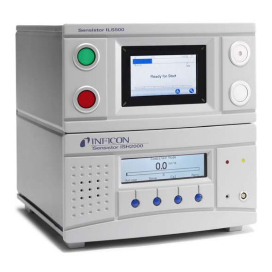
ILS500 Description ILS500 is manually controlled using the START and STOP buttons and the menu system of the touch panel. The screen also shows the steps of the test sequence graphically and in plain text. Front View ILS500 Front View Red lamp Green lamp ILS500 Touch panel... -
Page 14: Rear View (Electrical)
Rear View (Electrical) Rear View (Electrical) Leak Detector Connection Port Safety Interface Fuses Power Switch Power Input Probe Control Port Control Output Tooling Interface Status Output Inputs 1 and 2 (optional) Ethernet Printer Port/RS232 For more information, see on page 85. ILS500 Description... -
Page 15: Configuring Ports And Interfaces (Electrical)
Configuring Ports and Interfaces (Electrical) Port/Interface Connect File Transfer Cable Leak Detector (for downloading custom APC drivers) Pin-to-Pin Cable (for external mounting of ISH2000) Connection Port Probe Safety Interface Emergency Stop Circuit Power Input Power Cable Probe Control Port APC Units Control Output Optional External Valves... -
Page 16: Rear View (Pneumatical)
Rear View (Pneumatical) Rear View (Pneumatical) Optional Port Test Port 2 Compressed Air Input Tooling Valve Outputs 1-4 Vacuum Gauge Vent Test Port 1 Tracer Gas Input Plugged Port Exhaust Notice Do not remove the plug from the plugged port in pos. 8. ILS500 Description... -
Page 17: Configuring Ports And Interfaces (Pneumatical)
Configuring Ports and Interfaces (Pneumatical) Port/Interface Port Thread Barb Fitting: Exhaust ID 25 mm (1 in.) Tracer Gas Input BSP 3/8" (NPT 3/8" adaptor included) Test Port 1 BSP 3/8" (NPT 3/8" adaptor included) Test Port 2 BSP 3/8" (NPT 3/8" adaptor included) Compressed Air Input BSP 3/8"... - Page 18 Pneumatical Plate Electrical Plate ILS500 Description...
-
Page 19: Hand Probe P50
Hand Probe P50 General Information Caution Do not expose the probe to a hydrogen concentration greater than 0.1% when the instrument is not operating, as this could damage or destroy the probe sensor. Caution Connection and disconnection of the sensor cable must be done with power OFF. Sensor can be damaged if power is on. -
Page 20: System Examples
System Examples ILS500 is equipped with a large number of functions for connection and leak testing of different kinds of objects. It is therefore possible to build a leak test station that suits the tested object and the requirements on testing speed etc. Three examples of test stations are given in the following sections. -
Page 21: Automatic Chamber Test
Automatic Chamber Test Automatic Chamber Test Power Compressed Air Tracer Gas Test Object Test Chamber Automatic Probe, AP29 ECO COMBOX This example is using the integrated tooling system for automatic connection of the tested object. ILS500 will automatically fill the object with tracer gas, and maintain the correct pressure. -
Page 22: Chamber Test With Leak Locating Option
Chamber Test with Leak Locating Option Chamber Test with Leak Locating Option Power Compressed Air Tracer Gas Hand Probe Test Chamber Automatic Probe, AP29 ECO COMBOX Active Probe Holder (optional) In this system example the ILS500 includes an Active Holder for Hand Probe, a Hand Probe and a Automatic Probe. -
Page 23: Setup
Setup Caution Check that you comply with all relevant legislation and safety standards before putting your ILS500 into service. Placement of the ILS500 Place the ILS500 on a flat surface, as close as possible to the test fixture and ventilation system. Some free space must be provided around the ILS500 to enable maintenance and service access. -
Page 24: Electrical Connections
Avoid to place the ILS500 close to hydrogen sources such as cigarette smoke, combustion engines, aluminum machining, lead battery charging stations and compressed air systems. Electrical Connections 6.2.1 Setting Up an Emergency Stop Caution To short-circuit is not recommended and should only be made for preliminary testing before connecting compressed gases or test tooling with moving parts. - Page 25 6.2.2 Connecting the Probe Use the Probe Cable to connect the Probe to the ILS500. Probe connectors are placed on the front and rear of the unit. Notice If you have purchased another type of probe than the Hand Probe P50, refer to the manual for that probe.
- Page 26 Top pin is number 1 For more information about the connection ports, see on page 85. Setup...
-
Page 27: Pneumatic Connections
Pneumatic Connections 6.3.1 Connecting Compressed Air Caution Make sure that compressed air is dry, well filtered and oil free. Recommended filter grade is 5 µm or finer. Inadequate filtering will result in increased maintenance. Caution Make sure to use adequate pressure and flow. For more information, see on page Use the hose to connect the compressor and the ILS500. - Page 28 Secure gas cylinder safely. Open the cylinder valve briefly to blow out dirt that may have collected in the outlet. Install the two stage gas regulator on cylinder. Turn regulator fully counter clockwise for zero output pressure. Connect a regular welding gas hose or similar between the Tracer Gas Port and the pressure regulator.
- Page 29 6.3.3 Connecting Exhaust to Air Vent Min 2 m (6.5 ft.) 100 mm (4 in.) Ø 25 mm (1 in.) Max 10 m (30 ft.) Ø Exhaust Recommendation ILS500 Exhaust Hose Bleed Air The exhaust gas should be directed out of the building. •...
- Page 30 6.3.4 Connecting to Test Port 1 and 2 • Use both Test Ports if applicable. • Hose ID ?8 mm (0.31 in.). • The hoses should be as short as possible. Notice The larger the test object, the more important to follow the recommendations above.
-
Page 31: Set Up Test Area
Set Up Test Area Large distance Test Area Recommendation Fresh Air Fan Exhaust Fan Test Area Test Building • Place fresh air intake on outer wall of building. • Place air intake far away from tracer gas exhaust, cargo bays and other hydrogen sources. -
Page 32: Menu System
Menu System ILS500 Display - 0 + 5,00 -0,70 Ready for Start Status Bar Main Display Navigation Button Bar (varies depending on menu) 7.1.1 Menu Buttons Use the menu buttons for quick navigation. Calibrate Load Recipe Settings Home Menu System... - Page 33 7.1.2 Navigation and Other Buttons Go Back Escape (changes will not be saved) Previous Page Next Page (changes will be saved) Activated Unactivated Selected Deselected Save Load (only shown if USB is connected) Open switch Closed switch 7.1.3 Entering Numbers and Text To change a value: Click on the value.
-
Page 34: Passwords
Passwords To access the menus, use default password "1234" for "Service". The password can be changed under Settings / Advance Settings / Password. Passwords Calibrate Log In Select Recipe Log Out Setup excl. Tooling Adv. Setup excl. Service Service Menu Setup User Notice Remember to change the passwords of all menus you want to protect. -
Page 35: Menu Overview
Menu Overview For information about parameter factory default settings, see on page 104. Notice The instrument is equipped with a Leak Detector ISH2000, which means that some settings are blocked. These settings are accessed using the ILS500 operator panel. Calibration Load Recipe Settings Hardware Setup... - Page 36 Settings Region Time Zone, Region and Daylight Time and Date Language Info 7.3.1 Settings Hardware Setup Recipes Test Settings Statistics Advanced Settings Region Calibration Settings Info Hardware Setup Hardware Setup One Probe connected! Hardware setup, one Probe connected. Hardware Setup Two Probes connected! Hardware setup, two Probe connected.
- Page 37 Test settings Test Settings Tooling Connection Pre Evacuation Gross Leak Test Tracer Gas Filling For more information see chapter 9 on page 44. Advanced Settings Advanced Settings Timers Service Menu Pressures Passwords Options IP-settings ISH2000 Advanced settings to fine tune the fill cycles and settings for service staff. Calibration Settings Calibration Settings Calibration Value...
- Page 38 Recipes Recipes Use Recipes Choose at startup Load Recipes Save Recipes Delete Recipes For more information, see chapter 9 on page 44. Statistics Statistics Total: Accepted: Rejected: Evacuation: Print Vacuum Decay: Blockage: Reset Gas Fill: Pressure Decay: Press 3 sec Gas Test: Information about test statistics and number cycles events during a test period.
- Page 39 Language Language Swedish English Japanese Italian German Language settings. Info Info Type: ILS500 Serial number: 0 CPU software v 3.00.08 Display version: 3.00.09 Backup Battery Level (3,0 V) Brightness display Instrument information, software versions, battery status and display light settings. Menu System 39...
-
Page 40: Using The Ils500
Using the ILS500 Warning Ensure that the tracer gas supply pressure (feeding the ILS500 tracer gas inlet) is set up properly. Caution To abort a test sequence and reset to standby, press STOP for 3 s. Notice The following description is an example for illustration only. The design of the text fixture, the use of probe(s) and tooling functions etc. -
Page 41: Run A Test
Step Comment Tracer Gas Filling Tracer gas filling before gas test. • Reveals internal blockages in tested object. Blockage Test • Ensures that connection lines and test fixture are correctly connected. The test object is filled through Test Port 1 while the pressure is recorded in Test Port 2. - Page 42 8.2.2 Place the Test Object Place the test object in the Test Chamber or connect it to one, two or more connection ports. Connect any extra equipment needed. 8.2.3 Perform a Test Caution Do not expose the probe to a hydrogen concentration greater than 0.1% when the instrument is not operating, as this could damage or destroy the probe sensor.
- Page 43 8.2.4 Disconnect Test Object Evacuate the gas or release the gas pressure. Remove the test object from the fixture. Notice Exercise care in the handling of tracer gas after use. Released tracer gas contaminates the surrounding air with hydrogen and can comprise subsequent measurements for some time.
-
Page 44: Recipes
Recipes A recipe is a collection of settings suited for a particular test setup. This is used to have different settings for different test objects. Recipe Overview Click Settings >> Recipes to enter the three Recipe Setting menus. Recipe Setting Use Recipes Choose at startup Load Recipe... -
Page 45: Create A Recipe
Delete Recipe Deletes the chosen recipe. A new window will open. Connect with Recipe Connects two recipes to form one test cycle. Write the name of the recipe to be included, or choose one from the list in Use from list. Use from list Shows all saved recipes.... -
Page 46: Test Settings
Test Settings Click Settings >> Test Settings to enter the two Test Settings menus. Test Settings Setup Tooling Connection Pre Evacuation Gross Leak Test Tracer Gas Filling Test Settings Setup Blockage Test Tracer Gas Test Gas Evacuation Tooling Disconnection Set which steps to include in the test sequence by selecting the ON boxes. Click Setup to the right of each selected step to enter the Setup menus. - Page 47 Stand-By STAND-BY Tooling Outputs Go to next step with Start Button and Tooling Inputs Delay Click on the Tooling Outputs to be activated in stand-by (between tests). Choose how to move on to the next step. - Set action in list. - Select Tooling Inputs.
- Page 48 Test Step Test Step Tooling Outputs Condition for starting test and Tooling Inputs Info Delay See Connection Step 1 - 3 above and follow the instructions. 9.3.2 Pre Evacuation Pre Evacuation Pre Evacuation Setpoint -0.70 Extended Pre Evacuation Gas Locate if gross leak -0.40 Locate if Evacuated below Pre Evacuation Setpoint...
- Page 49 9.3.3 Gross Leak Tests Gross Leak Test Evacuation Timeout 10.0 s Vacuum Decay Test - before gas test Pressure Decay Test - during gas test Evacuation Timeout Object will be rejected if Pre Evacuation Setpoint is not attained within time set. Vacuum Decay Test If to be included in the test sequence, select the box and click the blue button to enter Pressure...
- Page 50 Pressure Decay Test Gas Pressure Decay Test Pressure Stabilisation Time Pressure Decay Test Time Pressure Decay Limit 0.10 Gas Locate if gross leak Pressure Stabilisation Time Delay time before Pressure Decay test begins. Pressure Decay Test Time Time during which pressure drop is recorded. Pressure Decay Limit Allowed pressure drop during test time.
- Page 51 Fill Setpoint Desired tracer gas fill pressure. Fill Timeout Object will be rejected if Pressure Setpoint has not been attained within this time. Cancels the fill if the test object has a major leak, opens, or if there are loose connections. External Fill Regulation If selected, this is the setpoint of fill pressure alarm.
- Page 52 9.3.6 Tracer Gas Test Depending on hardware, the following windows will be displayed. Tracer Gas Test APC Timers Reject Level 10.0 Measuring Unit Correlation Value Purge Level 95%N2/5%H2 Displayed Gas Tracer Gas Test Reject Level cc/s Measuring Unit Correlation Value Purge Level Displayed Gas 95%N2/5%H2...
-
Page 53: Optimizing The Test Cycle
9.3.7 Gas Evacuation Gas Evacuation -0,30 Gas Evacuation Setpoint Extended Gas Evacuation Set desired level of Gas Evacuation. Gas Evacuation Setpoint -30 kPa (-0.3 bar, -4.4 psi) creates 30% vacuum, which is adequate for most applications. Extended Gas Evacuation Extends time for gas evacuation, after Gas Evacuation Setpoint has been reached. - Page 54 This section is a guide for optimizing step 2, 3 and 5. Notice For optimizing the gas test step, refer to the application manual, the Hydrogen Method. Optimizing the Pre Evacuation Step Notice The fastest way to fill a pipe like object is to use push-through filling. That does not require pre evacuation.
- Page 55 A = Fill Pressure B = 1 atm C = Tracer Gas Fill Factor D = Evacuation Pressure - - - - - - - - 0,05 0,07 - - - - - - - - - - - - - - - 0,05 The average hydrogen concentration in this example will be 0.8 (80%).
- Page 56 We will now have: - - - - - - - - 0,03 0,056 - - - - - - - - - - - - - 0,03 of air left in the pipe. This is equivalent to 0.57 m (1.9 ft.). This air volume is normally small enough to be mixed into the tracer gas by turbulence and diffusion.
- Page 57 Optimizing the Tracer Gas Filling Regulation of the tracer gas pressure can either be controlled by: • the ILS500 • an external pressure regulator Notice The ILS500 is set to regulate internally as default. 9.6.1 External Pressure Regulation Notice External Pressure Regulation does not support recipes with different test pressure (i.e.
-
Page 58: Calibration
Calibration 10.1 About Calibration It is important to have a correct calibration when measuring the size of a leak in Measure Mode and Combined Mode. There are two ways to calibrate the probe: • Calibration gas (recommended) Has a known concentration of hydrogen (10 ppm recommended). •... - Page 59 Calibration Settings Calibrate: At Startup After Recipe change Every test Calibration Repeat Pause Calibration Settings Cal. Leak in test cycle Cal. Leak Pressure Set Cal. Leak Pressure 1.00 bar Prevent Start Automatic (Active Probe only) Max. Attempts Calibration Value Set to the same as stated on the calibration certificate issued for the leak or gas.
-
Page 60: How To Calibrate
Cal. Leak in Test Cycle Select the box if the calibration leak is integrated in a test object or in the chamber wall. A complete test cycle will be performed during calibration (Active Probes only). Cal. Leak Pressure This option is only visible if Leak in Test Cycle is selected.... - Page 61 Replace it with Tracer Gas. Attach it to the leak. 10.3.2 Calibrate the Probe Hand Probe Expose the probe to the background air. Press cal. button on ISH2000. Press Start Button or push Probe Button. Expose the Probe to the Calibration Leak or Calibration Gas. Wait while the Calibration Time bar is moving.
-
Page 62: Troubleshooting
Troubleshooting 11.1 Fault Symptoms Fault Symptom Fault Measures Evacuation Failed Failed to reach vacuum Check the compressed air within the specified time. supply. Large leak on Test Object or connections. Gas Fill Failed Failed to fill to the right Check the incoming gas pressure within the pressure. - Page 63 Hardware Test Press “TEST” OUTPUTS ILS500 plugged Vacuum: 0.00 ILS500 + Object Pressure: 0.00 TEST STOP • For troubleshooting and testing of the system, use Service menu. • For remote troubleshooting, use Service Run menu. • Venturi Pump and all Gas Valves can be tested automatically. The hardware test is a diagnostic tool helping you in preventive maintenance as well as service and repair.
- Page 64 Pressure and Vacuum Sensors Hardware Test Pressure and Vacuum Sensors Zero Points are OK Vacuum: 0.00 Pressure: 0.00 CONTINUE STOP Zero points of pressure and vacuum sensors are tested. Possible results: • Zero Points are OK • Vacuum Zero Point not OK Offset zero point can result in: •...
- Page 65 Venturi Pump Hardware Test Venturi Pump Max Vacuum OK Vacuum: -0.88 Pressure: 0.00 CONTINUE STOP Checking max vacuum of Venturi pump. Possible results: • Max Vacuum OK • Poor Max Vacuum Poor max vacuum can result in: • Failed pre-evacuation •...
- Page 66 Vacuum Sensor Valve Hardware Test Vacuum Sensor Valve Valve works! Vacuum: 0.00 bar Pressure: 0.00 CONTINUE STOP This checks that the valve shuts to protect vacuum sensor before filling. Possible results: • Valve works • Faulty! Malfunction can result in: •...
- Page 67 Test Port 2 Valve Hardware Test Test Port 2 Valve Valve works! Vacuum: 0.00 bar Pressure: 0.00 CONTINUE STOP Notice This test will fail if both test ports are connected to a test object. Proceed and then repeat the entire hardware test sequence with both ports plugged to perform this test step.
- Page 68 External Gas Leaks Hardware Test Check for Leaks with Hand Probe 0.00 bar Vacuum: Pressure: 0.50 CONTINUE STOP The ILS500 is now prepared for a manual test for external leakage. Use the hand probe to check for leakage Start by checking all connections between the ILS500 and your test object. Follow each test line carefully and check every joint.
- Page 69 Evacuation Valve Hardware Test Evacuation Valve Valve works! 0.00 bar Vacuum: Pressure: 0.00 CONTINUE STOP This step tests that evacuation valve opens to release tracer gas to exhaust. Same test as previously but under pressure instead of vacuum. Possible results: •...
- Page 70 Indicator Lamps Hardware Test Lamp in Start Button 0.00 bar Vacuum: Pressure: 0.00 CONTINUE STOP Hardware Test Green Lamp (Top Left) 0.00 bar Vacuum: Pressure: 0.00 CONTINUE STOP Hardware Test Red Lamp (Bottom Left) 0.00 bar Vacuum: Pressure: 0.00 CONTINUE STOP This is a “manual”...
- Page 71 START and STOP buttons Hardware Test Press Start Button (Top Right) 0.00 bar Vacuum: Pressure: 0.00 STOP Hardware Test Press Stop Button (Bottom Right) 0.00 bar Vacuum: Pressure: 0.00 STOP This is a “manual” test. The test continues when the correct button is pressed. The test checks the activated START and STOP buttons only.
- Page 72 11.2.1 Hardware Error Messages Error Message Reason for Error Corrective Action* Detector Power Off No power to the Leak Check the power cable to Detector. the detector (internal or external). Detector Error + Check Probe cable disconnected. Connect cable. Probe and Cable** Detector Error + Check Gas sensor damaged.
- Page 73 11.2.2 Interpretation of Hardware Test Results Use the table below, to correct errors detected by the hardware test routine. Tested Unit Tested Feature Reason for Error Action Evacuation Valve Internal leaks Dirty or worn valve seals. Replace clean evacuation valve. Venturi Pump Maximum vacuum Compressed air pressure...
- Page 74 Tested Unit Tested Feature Reason for Error Action Tracer Gas Fill Valve Internal leaks Dirty or worn valve seals. Replace or clean tracer gas fill valve. Leaking pilot valve. Replace fourth valve from bottom in pilot valve ramp. Test Port 2 Valve Function Dirty or broken pilot valve.
-
Page 75: Maintenance Instructions
Maintenance Instructions Caution Do not open the detector! Service of this equipment may only be carried out by service organizations authorized for this purpose by INFICON. There are three different parts that needs regular maintenance: • Venturi Pump Needs regular cleaning. -
Page 76: Maintenance Plan
12.2 Maintenance Plan Part Interval Action Venturi Pump 3 months Perform a Hardware Test. Check Ultimate Vacuum. Clean venturi nozzles when necessary. Evacuation, Fill and 3-6 months* Perform a Hardware Test. Test Port 2 Valves Check condition of valves. Replace or clean valves when necessary. Vacuum Sensor Valve 12 months Perform a Hardware Test. -
Page 77: Maintenance
12.3 Maintenance 12.3.1 Tools and Safety Equipment When performing regular maintenance of the ILS500 the following equipment is needed. Description Note Allen Keys (Hexagonal 3 and 4 mm) Torx Key (T25) Screwdriver (Philip 1 or Pozidrive 1 Protective Eyewear When performing tooling output test. - Page 78 Tracer Gas Fill Valve Test Port Valve 2 Vacuum Sensor Control Valve Pressure Sensor (HP model only) Vacuum Sensor Pressure Sensor Pilot Valve Ramp Valve Position 5A+6A Main Air Valve 5B+6B Venturi Pump Supply Evacuation Valve Tracer Gas Fill Valve Test Port 2 Valve Sensor Protection Valve Tooling Valve 1...
- Page 79 12.3.4 Replacing the Venturi Pump Remove the exhaust hose from the barbed hose fitting Unscrew and remove the barbed hose fitting and the plastic washer. Use a 4 mm Allen key to remove the four screws holding the Venturi pump. Remove the o-ring under the Venturi.
- Page 80 Install new Venturi or use compressed air jet and a cotton bud, pipe cleaner or small brush to clean the nozzles inside the Venturi. Replace hose fitting on Venturi inlet. Reconnect inlet hose. Clean o-ring and install in groove on valve manifold. 10Reinstall and tighten the four screws.
- Page 81 12.3.5 Replacing Gas Valves Use a 3 mm Allen key to remove the four screws holding the valve to be changed. Lift the old valve out and put the new valve in. Notice the correct orientation in the picture below. Tighten the screws 2-3 mm (0.08-0.12 in.) at a time moving the key from screw to screw so that the valve doesn’t tilt much.
- Page 82 12.3.6 Replacing Pilot Valves Use small screw driver to loosen the screw holding the valve. You must back the screw all the way out until you feel it “jumping” in the thread entrance. Push down on the LEDs while pressing the screw down until you feel the locking mechanism “snap”.
-
Page 83: Functional Verification
12.3.7 Replacing Sensors Caution Service of the sensors may only be carried out by service organizations authorized for this purpose by INFICON. 12.4 Functional Verification See Perform Hardware Test on page 62. Maintenance Instructions 83... -
Page 84: Service
Service Caution Do not open detector! Service of this equipment may only be carried out by service organizations authorized for this purpose by INFICON. Caution If the detector suffers external damage, it must be checked and repaired by a service organization authorized by INFICON. -
Page 85: Technical Data
Technical Data 275 mm (10.8 in.) 364 mm (14.3 in.) 14.1 Electrical Specifications Electrical Supply Mains Voltage Single Phase 110-240VAC 50/60 Hz Current 1.0 A at 100 VAC 0.45 A at 230 VAC Power Rating 120 W max 33 W typical average Inrush Current Max 40 A Mains Connector... -
Page 86: Pneumatic Specifications
Communication Ports Data rate 1200-115200 baud Data bits Stop bits Parity None Flow control None 14.2 Pneumatic Specifications Compressed Air Supply Pressure Std Model 0.35–0.7 MPa (3.4–6.9 bar) (50–100 psi) Reduced vacuum capacity below: 0.5 MPa (4.8 bar) (70 psi) HP model 0.5–0.7 MPa (4.8–6.9 bar) -
Page 87: Other Data
Pneumatic Valve bore* 7 mm (0.28 in.) *Capacity is given for 500 mm (20 in.) of ID 10 mm (0.4 in.) hose between ILS500 and test volume. Evacuation Max vacuum -85 kPa (-12.3 psi) Capacity 0.4 s/l to -50 kPa (-7.2 psi) 1.5 s/l to -80 kPa (-11.6 psi) Filling Capacity at 1 MPa supply... -
Page 88: Interfaces And Connectors
14.4 Interfaces and Connectors All interfaces signals except the serial. Communication interfaces are discrete 24 VDC logic signals. Output signals (OUT) are sourcing transistor outputs. Input signals (IN) are transistor inputs. Max current of each signal is given in the tables below. Total current (sum) must, however, be within instrument specification. - Page 89 Printing of results The printer port prints the result of every test. In hand probe mode the result printed is “ACCEPT” or “REJECT” followed by date & time and recipe name (if used) and end Char New Line (0A, LF).<09> (Char Tab, 09) is used as a separator. For Example: "TEST_ACCE<09>2013-09-04 13:23:03<09>Factory Default<0A>"...
- Page 90 Commands The printer port can also be used to control the ILS500. The most commonly used functions can be started/configured over the RS232 interface. Always use New Line (0A,LF) as end character. Command Action M<0A> Starts a test cycle. Q<0A> Stop N<0A>...
- Page 91 14.4.2 Input 1 (Optional) Connector: 5 pin male Weidmüller, Omnimate BL3.5. Mating screw terminal included. Purpose: Options port 1. Optional analogue or digital input (not supported by std software). Signal Type Load Comment +24 VDC SUPPLY 250 mA Option supply. VIN1 -60 mA Voltage input:Digital 24 VDC or...
- Page 92 Signal Type Load Comment COM/SHLD +/-30 mA Shield/screed connection. 14.4.4 Status Output Connector: 6 pin male Weidmüller, Omnimate BL3.5. Mating screw terminal included. Purpose: Test Status Outputs. Sourcing 24 VDC transistor outputs. Signal Type Load Comment RUNNING 0.5 A Cycle running. ACCEPT 0.5 A Tested part accepted.
- Page 93 Purpose: Electrical tooling interface. Signal Type Load Comment +24 VDC SUPPLY 300 mA Tooling switch supply (e.g. proximity switch). -7 mA Tooling switch 1. -7 mA Tooling switch 2. -7 mA Tooling switch 3. -7 mA Tooling switch 4. MARKER* 0.5 A Marker output.
- Page 94 Signal Type Load Comment EXTSTOP -7 mA Stop button return side (NO contact) or contact to +24 VDC. EVAC1 0.5 A Venturi valve output. EVAC2 0.5 A Evacuation valve output. GASFILL 0.5 A Fill valve output. OPTOUT 0.5 A -1.0 A Common GND for outputs.
- Page 95 Signal Type Load Comment DET_WAIT 0.5 A Output of ISH2000 APC system. OUT_0 0.5 A Output of ISH2000 APC system. OUT_1 0.5 A Output of ISH2000 APC system. OUT_2 0.5 A Output of ISH2000 APC system. OUT_3 0.5 A Output of ISH2000 APC system. OUT_4 0.5 A Output of ISH2000 APC system.
- Page 96 Signal Type Load Comment +24 VDC SUPPLY 2.5 A AUX1 +/-1-5 A* Terminal 1 of safe relay contacts for auxiliary external use. AUX2 +/-1-5 A* Terminal 2of safe relay contacts for auxiliary external use. Not used SAFESPLY** SUPPLY -2.5 A 24 VDC supply from EXTERNAL emergency stop circuitry.
- Page 97 Connector: 9 pin male D-sub. Purpose: For downloading of APC drivers. Cable: Standard female to female file transfer cable (null modem) for downloading APC drivers. Signal Specification Not used Standard RS232C Data rate 115200 baud Data bits Not used Stop bits Parity none Not used...
- Page 98 USB is connected Recipe Setting USB Memory connected Import from USB Export to USB An icon for USB is shown when installing the USB flash drive. Import Recipe from USB Importing database table Recipe1 from csv-file... USB Memory connected Import from USB Export to USB When importing recipes all recipes are imported from a file named Recipe1.csv.
-
Page 99: Spare Parts And Accessories
Spare Parts and Accessories Pos. Part Type Description Part no. Hand Probe With a rigid neck. 590-780 P50-FLEX With a flexible neck. 590-790 Hand Probe Sensor For sensor replacement on P50 590-292 Hand Probe. Spare Parts and Accessories 99... - Page 100 AP29 ECO Sniffer flow 1 cc/s 590-036 Sniffer flow 3 cc/s 590-035 AP55 590-550 AP57 590-555 COMBOX To connect ILS500 to AP29 ECO. 590-820 For a complete list of all spare parts and accessories, please contact: support.sweden@inficon.com Spare Parts and Accessories...
-
Page 101: Support From Inficon
Customer Service Representative. You must obtain a Return Material Authorization (RMA) number from the Customer Service Representative. If you deliver a package to INFICON without an RMA number, your package will be held and you will be contacted. This will result in delays in servicing your instrument. -
Page 102: Declaration Of Conformity
**Some deviations from standard exist. Contact manufacturer for details. Information related to the Machinery Directive (2006/42/EC): Sensistor ILS500 is intended (when appropriate) to be incorporated into machinery or to be assembled with equipment to constitute machinery covered by Directive 98/37/EG, as amended;... -
Page 103: Declaration By The Manufacturer
The delivered equipment (Sensistor ILS500) is intended to be connected to an emergency stop circuit. The enclosed plug with cable jumper is only intended for testing the equipment when not... -
Page 104: Appendix
Appendix Parameter Index Parameter Range Factory Default Customer Modification Automatic (Active Probe) Automatic probe type switch Block Test Pressure 0.3 bar Blockage Test Time Blockage Test Calibrate: After recipe change Calibrate: At startup Calibrate: Every_test 50 / OFF Calibration Coefficient Calibration repeat pause 30 s Choose at startup... - Page 105 Parameter Range Factory Default Customer Modification Gas Locate if failure (vacuum decay) Gas Locate if failure (pressure decay) Locate after Gas Leak Locate if evacuated below -0.4 bar Locating Pressure 0.3 bar Manual APC Measurement Marker Output Marker Output High if Leak Min.
- Page 106 Parameter Range Factory Default Customer Modification Two-Hand Control Use Recipes Vac. Stabilisation Time Vacuum Decay Limit 0.1 bar Vacuum Decay Test Vacuum Decay Test Time Wait Start if signal...
Need help?
Do you have a question about the Sensistor ILS500 and is the answer not in the manual?
Questions and answers