
Related Manuals for Inficon CDG045D2


Summary of Contents for Inficon CDG045D2
- Page 1 Communication Protocol ® EtherCAT for Capacitance Diaphragm Gauges CDG045D, CDG045D2, CDG100D, CDG100D2, CDG160D, CDG200D tira68e1 (2013-05)
-
Page 2: General Information
V0.4.4 (→ [13]). We reserve the right to make technical changes without prior notice. Product Identification In all communications with INFICON, please specify the information on the product nameplate. For convenient reference copy that information into the space provided below. -
Page 3: Validity
Validity This document applies to products of the temperature controlled CDG045D, CDG045D2, CDG100D, CDG100D2, CDG160D and CDG200D series with EtherCAT interface. Part numbers of standard products are indicated below. OEM products have other part numbers and different parameter settings (e.g. factory setting of setpoint) as defined in the corresponding ordering information. -
Page 4: Table Of Contents
Contents General Information Intended Use EtherCAT–Interface Product Identification Validity Trademark Patents Contents 1 Technical Data 2 Interface Connection 3 Operation 3.1 Introduction 3.2 Front View 3.3 Indicators and Switches 3.3.1 <RUN> LED 3.3.2 <ERR> LED 3.3.3 <LA> LED (<IN> Port) 3.3.4 <LA>... -
Page 5: Tira68E1 (2013-05) Cdgxxxd.cp
Appendix Literature For cross-references within this document, the symbol ( → XY) is used, for cross- references to further documents, listed under literature, the symbol ( → [Z]). tira68e1 (2013-05) CDGxxxD.cp... -
Page 6: Technical Data
1 Technical Data Further technical data → [1], [2], [3]. EtherCAT interface Communication protocol protocol specialized for EtherCAT Communication standards IEC 61158 -2 (Ed 4.0) IEC 61158 -3/4/5/6-12 (Ed 1.0) Data rate 100 Mbps Node address Explicit Device Identification Physical layer 100BASE-Tx (IEEE 802.3) EtherCAT connector... -
Page 7: Interface Connection
2 Interface Connection Making an EtherCAT interface For operating the temperature controlled CDGxxxD gauge via EtherCAT, two cable interface cables conforming to the EtherCAT standard are required. If no such cables are available, make two according to the following indications. Cable type Ethernet Patch Cable or Crossover Cable (CAT5e quality) with FCC68 connector. -
Page 8: Operation
3 Operation 3.1 Introduction Via the EtherCAT interface, the following and further data are exchanged in the standardized EtherCAT protocol: • Pressure reading • Pressure unit (Torr, mbar, Pa) • Zero adjustment • Status and error messages • Status of the switching functions •... -
Page 9: Indicators And Switches
3.3 Indicators and Switches 3.3.1 <RUN> LED Displays the operating status. Color LED State Description INIT (initialization status) or no power applied to device. blinking PREOP (pre-operational status). (200 ms on 200 ms off) green single flash SAFEOP (safe-operational status). (200 ms on Communication of cyclic data transfer running. -
Page 10: Device Address Switch
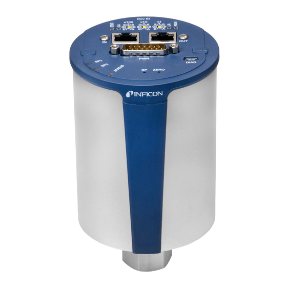
3.3.5 Device Address Switch During device initialization, the device address switches are read by the device firmware. This device address is supported to the master as Explicit Device x100 Identification. Example: Value of the Explicit Device ID = 0xDDD (dec 3549): 0x100 * 0xD (dec 3328) + 0x10 * 0xD (dec 208) + 0x1 * 0xD (dec 13) x100 tira68e1... -
Page 11: Object Structure
4 Object Structure This chapter describes the CANopen over EtherCAT (CoE) Object Dictionary. 4.1 Object Dictionary The objects in the CoE Object Dictionary can be accessed with SDO services, and many of the dictionary objects can be mapped for cyclic communication in PDOs. structure Each object is addressed using a 16-bit index and an 8-bit subindex. -
Page 12: Communication Profile Objects (0X1000
4.2 Communication Profile The objects of the communication profile describe the basic EtherCAT properties of the CDGxxD and are common to all EtherCAT slaves using the CoE Objects communication protocol. The objects are described in following table: (0x1000…0x1FFF) Index DataType Access PM Name 1000... -
Page 13: Manufacturer-Specific Profile Objects (0X2000
(conluded) Index DataType Access PM Name 1A02 TxPDO Transmit PDO Mapping 0x01 Reading Valid Module 2 0x02 Overrange Exceeded Module 2 0x03 Underrange Exceeded Module 2 0x04 Padding Bits 1 (5 bit) 0x05 REAL Sensor Value Module 2 1A03 TxPDO Transmit PDO Mapping, User Mapping 1C00 0x01... -
Page 14: Manufacturer Configuration Module 1
Index DataType Access PM Name 4.3.3 Manufacturer 2800 0x01 BYTE Safe State Configuration Module 1 0x02 REAL Safe Value 0x03 BOOL Alarm Enable 0x04 BOOL Warning Enable 0x05 REAL Alarm Trip Point High 0x06 REAL Alarm Trip Point Low 0x07 REAL Alarm Hysteresis 0x08... -
Page 15: Manufacturer Configuration Module
Index DataType Access PM Name 4.3.4 Manufacturer 2801 0x01 BYTE Safe State Configuration Module 2 0x02 REAL Safe Value Subindex 0x01 Specifies the behavior for the Value for states other than Valid. Safe State Zero Full Scale Hold last value Use safe value Subindex 0x02 Safe Value: The value to be used for Safe State = Safe Value. -
Page 16: Input Common
Subindex 0x03 Indicates whether the Value parameter contains a value in under range. Reading Valid No Underrange Exceeded Underrange Exceeded Index DataType Access PM Name 4.4.3 Input Common 6010 0x0E BOOL TxPdoState 0x11 REAL Sensor Value Subindex 0x0E Is set if the device is not in Safe State (value (I 0x6nn0, SI 0x11) = valid) TxPdoState Invalid Valid... -
Page 17: Configuration Area (0X8000
Subindex 0x01 Status High Trip High Trip not assert High Trip assert Subindex 0x02 Status Low Trip Low Trip not assert Low Trip assert 4.5 Configuration Area (0x8000…0x8FFF) Index DataType Access PM Name 4.5.1 Configuration 8001 0x12 REAL Offset Customer Specific Capacitance Diaphragm Subindex 0x12 Customer-specified Offset which shall be added to the Value parameter of the... - Page 18 Measurement signal (Pressure p) High Trip Hysteresis High Trip Point Low Trip Hysteresis Low Trip Point Time t active active active active active Index DataType Access PM Name 800E 0x01 BOOL High Trip Enable 0x02 BOOL Low Trip Enable 0x11 REAL High Trip Point Limit 0x13...
-
Page 19: Configuration Trip Point 2
Subindex 0x1A Object index of active source of (I 0x900E SI 0x01) Input Value. Source Index Bit 16…31 Index Bit 08…15 Subindex Bit 00…07 Reserved 4.5.3 Configuration Trip Calculating the High Trip Point and Low Trip Point → 4.4.7. Point 2 Index DataType Access... -
Page 20: Information Area (0X9000
4.6 Information Area The Information Data object defines the input process data. (0x9000…0x9FFF) Highest / lowest Indicated measurement value pressure Error Overrange Measurement range Underrange Error Real pressure p0 p1 p2 p3 The "measurement range" is the range between minimum and maximum pressure, where the reading of the gauge is within the specified measurement uncertainty limits. -
Page 21: Information Capacitance Diaphragm
Index DataType Access PM Name 4.6.1 Information 9001 0x01 UINT Sensor Warning Capacitance Diaphragm 0x02 UINT Sensor Alarm Subindex 0x01 Sensor Warnings Bit 0 Not at temperature Bit 1…8 Bit 9 Electronics Warning Bit 10…13 Bit 14 Low Warning Exception Bit 15 High Warning Exception Subindex 0x02... -
Page 22: Device Area (0Xf000
Index DataType Access PM Name 4.6.4 Information Trip 900E 0x01 REAL Input Value Trip Point 1 Point 1/2 900F 0x02 REAL Input Value Trip Point 2 Subindex 0x01 Input Value Trip Point 1: Trip Point Input value as referenced by Source Index (I 0x800E, SI 0x0E). -
Page 23: Active Device Warning Details
4.7.5 Active Device Warning The "active device warning details" parameter describes the warning state of the complete device. Details Index DataType Access PM Name F381 0x01 UDINT Active Device Warning Details Device 0x02 UDINT Active Device Warning Details Module 1 0x03 UDINT Active Device Warning... -
Page 24: Latched Device Warning Details
Subindex 0x01 Active Device Error Details (Index F383) Bit 0…2 Bit 3 EEPROM exception Bit 4…31 Subindex 0x02 Active Device Error Details (Index F383) Bit 0…8 Bit 9 Electronics failure Bit 10…13 Bit 14 Low Alarm Exception Bit 15 High Alarm Exception Bit 3…31 0 (reserved) Subindex 0x03... -
Page 25: Latched Device Error Details
Index DataType Access PM Name 4.7.8 Latched Device Error F393 0x01 UDINT Latched Device Error Details Details Device 0x02 UDINT Latched Device Error Details Module 1 0x03 UDINT Latched Device Error Details Module 2 F394 0x01 UDINT Latched Manufacturer Error Details Subindex 0x01 Latched Device Error Details Device: Latched version of 0xF383:01. -
Page 26: Trip Point Output All
4.7.13 Configure Device F840 0x01 UDINT Data Units Subindex 0x01 Unit of the Value of the Analog Input Sensor Instance and all related parameters. Trip Point Output All Instance 0x00220000 Pascal 0xFD4E0000 mbar 0x00A10000 Torr 0x00E00000 Counts (INFICON) tira68e1 (2013-05) CDGxxxD.cp... -
Page 27: Information Device
Index DataType Access PM Name 4.7.14 Information Device F940 0x01 UDINT Measurement Principle 0x02 BYTE Number of Sensors 0x04 V_STRING SW Version VPG PCB F9F0 V_STRING Manufacturer Serial Number F9F1 0x01 UDINT CDP Functional Generation Number Module 1 0x02 CDP Functional Generation Number Module 2 F9F2... -
Page 28: Command Zero Adjust
Subindex 0x04 (F940) If the device consists out of several software portions this parameter should be used. Using standard a.b.c.d format to describe a version: SW Version VPG PCB (Index F940) Mayor revision Minor revision Development revision Vendor specific i.e. 1.0.1.2 4.7.15 Command Zero Adjust Execution of this command will start a Zero Adjust operation. -
Page 29: Device Reset Command
Subindex 0x01 Command Byte 0 0: Full Scale Adjust Byte 1 Index of the Sub Sensor Instance (1-8) Byte 2…5 Full Scale value (Data format: REAL, always 0) Subindex 0x02 Status (supported values) Last command completed, no errors, no reply available Last command completed, no errors, reply available Last command completed, errors present, no reply available... -
Page 30: Exception Reset Command
Subindex 0x03 Response Byte 0 See Subindex 0x02 Byte 1 Unused Byte 2…n Unused 4.7.18 Exception Reset Execution of this command clears the latched exceptions. Command Index DataType Access PM Name FBF1 0x01 V_STRING Command 0x02 BYTE Status 0x03 V_STRING Response Subindex 0x01 A device reset is initiated when the following byte sequence is sent. - Page 31 Subindex 0x02 Status (supported values) Last command completed, no error, no response Reserved Last command completed, error, no response Reserved Command is executing Subindex 0x03 Response Byte 0 See Subindex 0x02 Byte 1 Unused Byte 2…n Unused tira68e1 (2013-05) CDGxxxD.cp...
-
Page 32: Appendix
Appendix Literature [1] www.inficon.com Operating Manual CDG045D tina51d1 (German) tina51e1 (English) INFICON AG, LI–9496 Balzers, Liechtenstein [2] www.inficon.com Operating Manual CDG100D tina52d1 (German) tina52e1 (English) INFICON AG, LI–9496 Balzers, Liechtenstein [3] www.inficon.com Operating Manual CDG160D, CDG200D tina53d1 (German) tina53e1 (English) INFICON AG, LI–9496 Balzers, Liechtenstein... - Page 33 Notes tira68e1 (2013-05) CDGxxxD.cp...
- Page 34 LI–9496 Balzers Liechtenstein Tel +423 / 388 3111 Fax +423 / 388 3700 reachus@inficon.com Original: English tira68e1 (2013-05) www.inficon.com t i r a68e1...
Need help?
Do you have a question about the CDG045D2 and is the answer not in the manual?
Questions and answers