
Related Manuals for Inficon SQM-160


Summary of Contents for Inficon SQM-160
- Page 1 SQM-1 60 ™ Multi-Film Rate/Thickness Monitor IPN 074-511-P1C...
- Page 3 SQM-1 60 ™ Multi-Film Rate/Thickness Monitor IPN 074-511-P1C ® www.inficon.com re achus@inficon.com ©2012 INFICON...
- Page 4 All other brand and product names are trademarks or registered trademarks of their respective companies. Disclaimer The information contained in this manual is believed to be accurate and reliable. However, INFICON assumes no responsibility for its use and shall not be liable for any special, incidental, or consequential damages related to the use of this product.
- Page 7 Seller product was not designed nor against any defects due to plans or instructions supplied to Seller by or for Buyer. This manual is intended for private use by INFICON® Inc. and its customers. Contact INFICON before reproducing its contents.
-
Page 9: Table Of Contents
Returning Your SQM-160 ........ - Page 10 SQM-160 Operating Manual Chapter 3 Operation Introduction..........3-1 Menu Selection.
- Page 11 6.2.1 Troubleshooting the SQM-160 ........6-2 6.2.2...
- Page 12 SQM-160 Operating Manual 6.3.4 Sputtering Sensor..........6-13 6.3.5...
-
Page 13: Introduction
Rate displays of 0.1 Å/s or 0.01 Å/s are user selectable. In addition, frequency or mass displays can be selected. Four relay outputs allow the SQM-160 to control source or sensor shutters, signal time and thickness setpoints, and signal crystal failure. -
Page 14: Related Manuals
When using this manual, please pay attention to the NOTES, CAUTIONS and WARNINGS found throughout. For the purposes of this manual they are defined as follows: NOTE: Pertinent information that is useful in achieving maximum SQM-160 efficiency when followed. CAUTION Failure to heed these messages could result in damage to the SQM-160. -
Page 15: General Safety Information
Refer all maintenance to qualified personnel. 1.2.3 Earth Ground The SQM-160 is connected to earth ground through a sealed three-core (three-conductor) power cable, which must be plugged into a socket outlet with a protective earth terminal. Extension cables must always have three conductors including a protective earth terminal. -
Page 16: How To Contact Inficon
Never interrupt the protective earth circuit. Any interruption of the protective earth circuit inside or outside the SQM-160, or disconnection of the protective earth terminal is likely to make the SQM-160 dangerous. This symbol indicates where the protective earth ground is connected inside the SQM-160. -
Page 17: Returning Your Sqm-160
If you deliver a package to INFICON without an RMA number, your package will be held and you will be contacted. This will result in delays in servicing your SQM-160. Prior to being given an RMA number, you may be required to complete a Declaration Of Contamination (DOC) form if your sensor has been exposed to process materials. -
Page 18: System Parameters
SQM-160 Operating Manual 1.4.3 System Parameters Measurement Period ... . 0.15 to 2 s Simulate Mode ....On/Off Frequency Mode . -
Page 19: General Specifications
SQM-160 Operating Manual 1.4.5 General Specifications Mains Power Supply... . . 100-120/200-240~, ±10% nominal, 50/60 Hz Power Consumption ... . . 20 W Operating Environment . -
Page 20: Unpacking And Inspection
1.6 Parts and Options Overview 1.6.1 Base Configurations SQM-160 ......SQM160-X-X-X Consult the figure below for possible configurations. -
Page 21: Accessories
1.6.2 Accessories Each sensor requires an oscillator kit to interface to the controller: SQM-160 10 ft. Oscillator Kit ..782-934-003-10 SQM-160 25 ft. Oscillator Kit ..782-934-003-25 SQM-160 50 ft. Oscillator Kit ..782-934-003-50 SQM-160 100 ft. - Page 22 SQM-160 Operating Manual This page is intentionally blank. 1 - 10...
-
Page 23: Quick Start
I/O, and wiring from hazardous voltages. Rack Installation The SQM-160 occupies a 3.5 in. high, half-rack space. Rack installation requires an optional half-rack adapter kit or a full rack extender kit. Install the SQM-160 in a 19 in. rack with the appropriate hardware. See section 3.21,... -
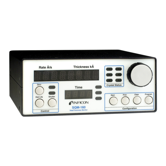
Page 24: Front Panel
If you have purchased the optional four sensor card, connect the four additional sensors to these four inputs. Power On Move the rear panel power switch to the On (|) position. The SQM-160 will briefly display its software and hardware versions, then go to normal operating mode. -
Page 25: Rear Panel
SQM-160 Operating Manual Configuration Section Push-button to enter/exit program mode. Push-button to cancel a change and return to original value. Push-buttons to move to Next/Previous parameter. Setpoint LEDs Illuminates when the indicated setpoint is reached. Crystal Status LEDs Illuminates when the crystal is active and operating properly. -
Page 26: System Connections
SQM-160 Operating Manual RS-232 Connection to computer for programming and data acquisition. See Chapter 5, Communications. USB/Ethernet Optional connection to computer USB or Ethernet port for programming and data acquisition. See Chapter 5, Communications. Option Card Provides four additional sensor measurement channels. - Page 27 Contains the electronics to operate the quartz crystal. The length from the oscillator to the crystal should be under 40 in. (1 m). 10' BNC Cable Connects the oscillator to the SQM-160. Lengths up to 100 ft. (30 m) are acceptable. Ground Wire A wire, preferably braided, that connects the vacuum system to the SQM-160 ground terminal.
-
Page 28: Film Setup
SQM-160 Operating Manual 2.6 Film Setup This section will help you set up the SQM-160 to measure a film. See Chapter 3, Operation, for detailed programming instructions. Enter Program Mode Press Program to enter the film setup menu. If the Crystal Life display is shown, press Xtal Life to return to Rate/Thickness mode, then press Program. -
Page 29: Depositing A Film
Zero Thickness If needed, press the Zero switch to zero the thickness reading. Start Deposition Apply power to the source evaporation supply. If the SQM-160 shutter relay is connected, press the Shutter switch to open the source shutter and begin deposition. - Page 30 SQM-160 Operating Manual This page is intentionally blank. 2 - 8...
-
Page 31: Operation
In program mode, Display 1 shows the parameter to be changed. Display 2 shows the selected parameter's value. NOTE: If Crystal Life is shown on the SQM-160 displays, press the Xtal Life switches to return the displays to normal rate/thickness or frequency display. -
Page 32: Film Menu
SQM-160 Operating Manual 3.3 Film Menu The Film Menu programs the SQM-160 for the materials that will be deposited. Ninety-nine films can be stored, but only one film is active at any time. Press Program to enter program mode. Use the Control Knob to scroll to the desired Film # (1-99). - Page 33 SQM-160 Operating Manual Table 3-1 Film Menu Display Description Range Default Units DENSITY Density of the material being deposited. 0.5 – 99.99 1.00 gm/cc Consult the Appendix A for common material densities. TOOLING Overall Tooling Factor for this film. See 10 –...
-
Page 34: System Menu
SQM-160 Operating Manual 3.4 System Menu The System Menu sets values that pertain to the overall functions of the SQM-160 and to the vacuum system's setup. System Menu parameters apply to all films. Press Program to enter program mode. Press Prev to enter the System Menu. - Page 35 When Sampling is ON the sensor shutter On/Off periodically “samples” the rate. After a period, the shutter closes and the SQM-160 “holds” the same rate reading until the next sample period. Sample and Hold times are set in the Film Menu.
-
Page 36: Sensor Selection
SQM-160 Operating Manual 3.5 Sensor Selection The SQM-160 comes standard with two sensor inputs. Four additional sensors are available by adding a Sensor Option Card. A specific sensor can be assigned to each film, or multiple sensors can be averaged for a film. The averaging option provides more uniform coverage of the deposition area and provides a backup sensor capability. -
Page 37: Sensor Frequency
Both values are used to determine the % life that is displayed in Xtal Life mode. When the sensor frequency drops below the minimum (or reads above the maximum), the SQM-160 indicates a sensor failure by blinking the Crystal Status display. To set sensor minimum and maximum frequencies: Press Program to enter Program mode. -
Page 38: Sensor Tooling
SQM-160 Operating Manual 3.7 Sensor Tooling Sensor Tooling adjusts for the difference in deposition rate between the sensor and the substrate being coated. It is an empirically determined value that matches the sensor readings to the vacuum system. Figure 3-4 Sensor Tooling... -
Page 39: Display Units
Press the Control Knob to accept the choice. Press Program to exit the System Menu and return to normal mode. 3.9 Crystal Life The SQM-160 calculates the remaining crystal life based on the FMin/Max values set in the System Menu (refer to section 3.4 on page 3-4). -
Page 40: Shutter Operation
Dual shuttered sensors provide a backup (secondary) sensor in case of primary sensor failure. When Relay 2 is programmed for Dual sensors in the System menu, the SQM-160 will automatically switch to Sensor 2 when Sensor 1 readings stop or become erratic. -
Page 41: Rate Sampling
SQM-160 Operating Manual 3.13 Rate Sampling In Rate Sampling mode, the SQM-160 opens a sensor shutter for a fixed time to "sample" the process rate, then closes the shutter and "holds" the last rate reading for a fixed time. While the shutter is closed (hold mode), the SQM-160 calculates thickness based on the last sampled rate. -
Page 42: Time Setpoint
SQM-160 Operating Manual 3.14 Time Setpoint The Time Setpoint provides a convenient way to signal a timed event. After a pre-programmed time period, the Time Setpoint closes a relay when the Zero switch is pressed. To program the Time Setpoint: Press Program to enter Program mode. -
Page 43: Thickness Setpoint
SQM-160 Operating Manual 3.15 Thickness Setpoint The Thickness Setpoint closes a relay when a programmed thickness is reached. This setpoint is independent from Final Thickness, which always closes the source shutter. To program the Thickness Setpoint: Press Program to enter Program mode. -
Page 44: Simulate Mode
SQM-160 Operating Manual 3.16 Simulate Mode In Simulate mode, the SQM-160 simulates attached sensors. It is an easy way to become familiar with the SQM-160 front panel controls and programming. You can open/close the shutter to simulate deposition, zero readings, and display crystal life. -
Page 45: Relay Operation
(1FormA) relays. However, each can be programmed to act as either normally-open or normally-closed during SQM-160 operation. It is important to keep in mind that all relays will open if the SQM-160 is turned off or loses power. section 3.20 on page 3-16 for relay wiring. -
Page 46: Analog Output Configuration
SQM-160 Operating Manual 3.19 Analog Output Configuration The SQM-160 analog outputs must be set to match the device that will be attached to the Rate or Thickness output. To set up the analog outputs in the System Menu: Press Program to enter Program mode. - Page 47 SQM-160 Operating Manual Table 3-3 Relay I/O Connections Function Description Pins Crystal Fail Relay Contacts close when all enabled sensors have failed. Relay 1 Time Setpoint, Dual If Relay 2 is set to TIME in the System menu, contacts close when Sensor, or Sensor 2 timer counts down to zero from its programmed Timer Setpoint value.
-
Page 48: Rack Mounting Procedure
The Half Rack Adapter kit mounts one SQM-160 to another 3.5 in. high instrument. It consists of two rack-mount ears and a small adapter bracket. Mount one rack mount ear to the SQM-160, and the other to the second instrument. Attach the two instruments using the adapter bracket. -
Page 49: Comm Software
Monitor to allow remote instrument setup and data logging. With the SQM160 Comm you can: Select a Film on the SQM-160 Thin Film Monitor, then open the shutter to start deposition. View SQM-160 readings in both numerical and graphical format. -
Page 50: Main Window
4.3 Main Window Figure 4-2 SQM-160 Comm Main Window The main window allows for basic SQM-160 setup and data logging. On program startup, it may take a few seconds to display the main window and read the Monitor's setup information. - Page 51 The remaining main window controls display readings from the SQM-160 Monitor. Graph ......Displays rate readings from the SQM-160. A...
-
Page 52: Data Log Menu
SQM-160 Operating Manual Average Rate ....The current deposition rate, based on the average of all sensors assigned to the selected film. Rate 1-6 ..... . The individual sensor rate readings. - Page 53 Once communications have been established, follow these steps to start data acquisition: Select the desired film from the list of SQM-160 films. Press Zero to zero the Monitor's thickness reading (optional). Press Open Shutter to start data acquisition. 4 - 5...
-
Page 54: Films Menu
SQM-160 are overwritten! Upload all ....Transfers films stored in the SQM-160 to the download list. They are automatically saved to the database also. - Page 55 Film Name ....The name that is displayed in the films database, films to download lists, and in the SQM-160 films menu. Names are limited to a maximum of eight alphanumeric characters.
-
Page 56: System Menu
SQM-160. Read ......Reads the SQM-160 system menu parameters into the System dialog box. -
Page 57: Communications Menu
SQM-160 serial communications connection. Figure 4-6 Communicatons Dialog Box To connect the SQM-160 Thin Film Monitor to your computer, you will need a 9 pin male to 9 pin female "straight thru" RS-232 cable. A cable is supplied with each SQM-160 monitor or can be purchased at any computer store. -
Page 58: Graph Options
ASCII command set detailed in section 5.3 on page 5-6 can be sent to the monitor and the responses from the SQM-160 can be recieved. 4.8 Graph Options Right click anywhere on the graph display on the main window to bring up the graph options. -
Page 59: Help Menu
SQM-160 Operating Manual 4.9 Help Menu On the main window, under the help menu, there is a help option and an about option. The help menu contains the information found in this chapter while the about menu displays program revision and technical support information. - Page 60 SQM-160 Operating Manual This page is intentionally blank. 4 - 12...
-
Page 61: Communications
5.1.1 RS-232C Serial Port RS-232C serial communications are accomplished through an industry standard 9-pin female connector found on the rear panel of the SQM-160. A mating male connector is required for attachment of a host interface. The host and the SQM-160 can be separated by up to fifty feet using multiconductor shielded data cable. -
Page 62: Tcp/Ip Ethernet Port
Most personal computers (PC) are configured to obtain the IP address, an address which defines the computer on the Internet, automatically from a server. To communicate directly with the SQM-160, the Internet protocol (IP) on the PC must be configured manually and an ethernet cable must be connected between the PC and the SQM-160. - Page 63 SQM-160 Operating Manual Select the Local Area Connection to be changed, right-click and select Properties. See Figure 5-2. Figure 5-2 Local Area Connection Properties On the General tab, select Internet Protocol (TCP/IP) and press the Properties button. See Figure 5-3.
- Page 64 IP address to use when communicating with the SQM-160. The SQM-160 is shipped from INFICON with a pre-assigned address of 192.168.1.200. To communicate directly with the SQM-160 from a PC, the PC must also be assigned an address that starts with 192.168.1 but cannot be set to 192.168.1.200.
-
Page 65: How To Change The Ip Address Of The Sqm-160
SQM-160 Operating Manual 5.1.3.2 How to change the IP address of the SQM-160 The IP address of the SQM-160 can be changed using the Dgdiscvr program on the CD-ROM. To change the IP address: Run dgdiscvr.exe and find the SQM-160 (it may take a minute, click Refresh.) Double-click on SQM-160 (should be highlighted.) -
Page 66: Communications Protocol
The SQM-160 communicates with a host computer via an ASCII based protocol. The SQM-160 defaults to 19,200 baud, 8 data bits, and no parity. The baud rate can be changed in the System Menu of the SQM-160, but is always 8 data bits with no parity. -
Page 67: Commands
SQM-160 Operating Manual NOTE: CRC calculation examples can be found in section 5.5, CRC Examples, on page 5-12. The response protocol received from the instrument is: <sync character><length character><response status character><1 to n data characters><CRC1><CRC2> The Sync character is always a "!" as in the sent command structure. The Length character, however, has a decimal 35 added to it instead of 34 like the command length character. -
Page 68: Command: B
SQM-160 Operating Manual embedded in a Label, use an underscore character '_'. Each parameter is separated by a space. Each film's parameters are accessed by using the ASCII character associated with film number directly after the Command. For example Film 1-9 are ASCII characters "1"... -
Page 69: Command: D
Example: ..... J A2 The SQM-160 has two channels available. 5.4.7 Command: L Parameters: ....[1..6] Description: . -
Page 70: Command: P
Description: ....Zero Time Example: ..... T A Zeroes time display on SQM-160. 5.4.15 Command: U Parameters: . -
Page 71: Command: W
Description: ....Read the Power-Up Reset flag. The Power-Up Reset flag is set during boot-up of the SQM-160 and stays set until read through the RS-232 interface. After the flag is read, it is reset and will not be set again until the SQM-160 is power cycled. -
Page 72: Crc Examples
SQM-160 Operating Manual 5.5 CRC Examples In this section you will find examples of code for calculating the CRC in Visual Basic, Java, and C++. Instructions for calculating the CRC are located in section 5.3 on page 5-6. ® 5.5.1 Visual Basic... - Page 73 SQM-160 Operating Manual End Sub Public Function LoByte(ByVal intNumber As Integer) As Byte ' Comments : Returns the low byte of the passed integer ' Parameters: intNumber - integer value for which to return the low byte ' Returns : byte...
-
Page 74: Java
SQM-160 Operating Manual PROC_ERR: MsgBox "Error: " & Err.Number & ". " & Err.Description, , _ "Shri" Resume PROC_EXIT End Function ® 5.5.2 Java private short calcCRC(byte[] str) { short crc = 0; short tmpCRC; int length = 1 + str[1] - 34;... - Page 75 SQM-160 Operating Manual short crc; public: short calcCRC( unsigned char * str) int length = (str != NULL) ? 1 + str[1] - 34 : 0; if (length > 0) { crc = (short) 0x3fff; for (int jx = 1; jx <= length; jx++) { crc = (short) (crc ^ (short) str[jx]);...
- Page 76 SQM-160 Operating Manual This page is intentionally blank. 5 - 16...
-
Page 77: Troubleshooting And Maintenance
SQM-160 Operating Manual Chapter 6 Troubleshooting and Maintenance 6.1 Troubleshooting Guide If the SQM-160 fails to function, or appears to have diminished performance, the following Symptom/Cause/Remedy charts may be helpful. CAUTION There are no user serviceable components within the SQM-160 case. -
Page 78: Troubleshooting
Oscillator and/or sensor a. Verify proper always on. not connected. Oscilator/sensor connections. b. SQM-160 malfunctioning. b. If available, insert a known working QCM, in place of suspect one; if the SQM-160 is confirmed bad, contact INFICON service department. c. Defective cable from c. -
Page 79: Troubleshooting Sensors
SQM-160 Operating Manual Table 6-1 General Troubleshooting (continued) SYMPTOM CAUSE REMEDY 3. Frequency reading is a. Temperature (of the a. Control the temperature of unstable or drifting crystal) is changing. An the chamber. Check watering AT-cut crystal frequency may cooling for flow and drift as much as 10 Hz/°C. - Page 80 SQM-160 Operating Manual Table 6-2 Troubleshooting Sensors SYMPTOM CAUSE REMEDY 1. Large jumps of thickness a. Mode hopping. a. Mode hopping is a reading during deposition. byproduct of active oscillation with a heavily damped crystal. Temperature stabilization is key in diminishing this.
- Page 81 SQM-160 Operating Manual Table 6-2 Troubleshooting Sensors (continued) SYMPTOM CAUSE REMEDY 2. Crystal ceases to oscillate a. Crystal struck by a. Thermally condition the during deposition before it particulate or spatter from source thoroughly before reaches the end of its normal molten source.
- Page 82 SQM-160 Operating Manual Table 6-2 Troubleshooting Sensors (continued) SYMPTOM CAUSE REMEDY 4. Crystal oscillates in a. Crystal was near the end a. Replace crystal. vacuum but stops oscillation of its life; opening to air after open to air. causes film oxidation which increases film stress.
- Page 83 Cyclic change in rate. d. Make certain source's sweep frequency is not "beating" with the SQM-160’s measurement frequency. 7. Large drift in thickness a. Crystal heating due to poor a. Clean or polish the crystal (greater than 200 Å...
-
Page 84: Troubleshooting Computer Communications
SQM-160 Operating Manual 6.2.3 Troubleshooting Computer Communications Table 6-3 Troubleshooting Computer Communications SYMPTOM CAUSE REMEDY 1. Communications cannot a. Improper cable a. Verify for cable be established between the connection. connections are seated host computer and the properly. SQM-160. b. USB Driver not installed b. -
Page 85: Front Load
SQM-160 Operating Manual 6.3.1 Front Load Follow the procedure below to replace the crystal in the Front Load sensor: (see Figure 6-1) Gripping the crystal holder with your fingers, pull it straight out of the sensor body. Gently pry the crystal retainer from the holder (or use the Crystal Snatcher; see Figure 6-6 on page 6-14). -
Page 86: Cool Drawer
SQM-160 Operating Manual 6.3.2 Cool Drawer Follow the procedure below to replace the crystal in a Next Generation Cool Drawer™ sensor: Using your thumb and index fingers, gently squeeze the sides of the retainer at the mid section then lift it up, away from the drawer, as shown in Figure 6-2. - Page 87 SQM-160 Operating Manual Figure 6-3 Cool Drawer - Replacing The Crystal Retainer Crystal Orientation Notch Handle Drawer 6 - 11...
-
Page 88: Bakeable Sensor
SQM-160 Operating Manual 6.3.3 Bakeable Sensor For the Bakeable sensor, the procedure is the same as the Front Load sensor except that you must first unlock the cam assembly by flipping it up. Once the crystal has been replaced, place a flat edge of the holder flush with the cam mechanism and lock it in place with the cam. -
Page 89: Operating Manual
SQM-160 Operating Manual 6.3.4 Sputtering Sensor Observe the general precautions for replacing crystals and follow the instructions below to replace the crystal in a sputtering sensor. Grip the body assembly with your fingers and pull it straight out to separate it from the water-cooled front cover. -
Page 90: Crystal Snatcher
SQM-160 Operating Manual 6.3.5 Crystal Snatcher Use the crystal snatcher, supplied with the sensor, as follows: Insert crystal snatcher into ceramic retainer (1) and apply a small amount of pressure. This locks the retainer to the snatcher and allows the retainer to be pulled straight out (2). -
Page 91: Crystal Sensor Emulator
SQM-160 Operating Manual 6.4 Crystal Sensor Emulator IPN 760-601-G2 NOTE: 760-601-G2 is fully compatible with all Thin Film Deposition Controllers. The Crystal Sensor Emulator option is used in conjunction with the Thin Film Deposition Controller to rapidly diagnose problems with the Deposition Controller's measurement system. -
Page 92: Diagnostic Procedures
The following diagnostic procedures employ the Crystal Sensor Emulator to analyze a constant Crystal Fail message. The symptom is a Crystal Fail message that is displayed by the SQM-160 even after the monitor crystal has been replaced with a new good monitor crystal. -
Page 93: Feedthrough Or In-Vacuum Cable
SQM-160 Operating Manual 6.4.1.2 Feedthrough Or In-Vacuum Cable Diagnostic Procedure Refer to Figure 6-8 on page 6-15. Remove the in-vacuum cable from the Sensor Head at point B. Connect the Crystal Sensor Emulator to the in-vacuum cable. If the Crystal Fail message disappears after approximately five seconds, the feedthrough and in-vacuum Cable are working properly. -
Page 94: Sensor Head Or Monitor Crystal Diagnostic Procedure
There must be electrical isolation between the center pin of the Microdot connector and the Sensor Head body. If the Sensor Head is found to be defective, contact INFICON to have the Sensor Head repaired. 6 - 18... -
Page 95: System Diagnostics Pass But
SQM-160 Operating Manual Connect the in-vacuum Cable to the Sensor Head. Verify there is continuity (<0.2 ohm) from the leaf spring contact in the Sensor Head to the center pin on the un-terminated end of the in-vacuum cable. ... -
Page 96: Sensor Cover Connection
Cool Drawer Dual Sensor Head CDD-XXXX Crystal12 Sensor Head XL12-XXXXXX RSH-600 Sensor Head 15320X-XX NOTE: The Crystal Sensor Emulator’s Sensor Cover will not fit the crystal holder opening of the older style INFICON transducers that have the soldered finger springs. 6 - 20... -
Page 97: Emulator Specifications
SQM-160 Operating Manual 6.4.3 Emulator Specifications Dimensions 1.58 in. diameter x 1.79 in. (40.13 mm diameter x 45.47 mm) Temperature Range 0 to 50 Frequency 760-601-G2: 5.5 MHz ±1 ppm at room temperature Materials ® 304 Stainless Steel, Nylon, Teflon , brass. - Page 98 SQM-160 Operating Manual This page is intentionally blank. 6 - 22...
-
Page 99: Calibration Procedures
7.1 Importance of Density, Tooling and Z-Ratio The quartz crystal microbalance is capable of precisely measuring the mass added to the face of the oscillating quartz crystal sensor. The SQM-160's knowledge of the density of this added material (specified in the density parameter in material grid) allows conversion of the mass information into thickness. -
Page 100: Determining Tooling
= Measured thickness A quick check of the calculated density may be made by programming the SQM-160 with the new density value and observing that the displayed thickness is equal to the measured thickness, provided that the SQM-160's thickness has not been zeroed between the test deposition and entering the calculated density. - Page 101 SQM-160 Operating Manual -- - ----------- - -- - 9.378 10 where: = density (g/cm ) of deposited film µ = shear modulus (dynes/cm2) of deposited film = density of quartz (crystal) (2.649 gm/cm µ...
- Page 102 SQM-160 Operating Manual where: = thickness of deposited film (kÅ) = starting frequency of the sensor crystal (Hz) = Final frequency of the sensor crystal (Hz) = Nominal blank frequency = 6045000 (Hz) z = Z-ratio of deposited film material...
-
Page 103: Measurement And Theory
SQM-160 Operating Manual Chapter 8 Measurement and Theory 8.1 Basics The Quartz Crystal deposition Monitor, or QCM, utilizes the piezoelectric sensitivity of a quartz monitor crystal to added mass. The QCM uses this mass sensitivity to control the deposition rate and final thickness of a vacuum deposition. When a voltage is applied across the faces of a properly shaped piezoelectric crystal, the crystal is distorted and changes shape in proportion to the applied voltage. -
Page 104: Monitor Crystals
SQM-160 Operating Manual effect provides a means of determining how much material is being deposited on a substrate in a vacuum system, a measurement that was not convenient or practical prior to this understanding. 8.1.1 Monitor Crystals No matter how sophisticated the electronics surrounding it, the essential device of the deposition monitor is the quartz crystal. - Page 105 SQM-160 Operating Manual reduces the intensity of response of the generally unwanted anharmonic modes; hence, the potential for an oscillator to sustain an unwanted oscillation is substantially reduced. Figure 8-2 Frequency Response Spectrum 1000 Frequency (in MHz) The use of an adhesion layer has improved the electrode-to-quartz bonding, reducing “rate spikes”...
-
Page 106: Period Measurement Technique
SQM-160 Operating Manual Figure 8-3 Thickness Shear Displacement displacement node 8.1.2 Period Measurement Technique Although instruments using equation [2] were very useful, it was soon noted they had a very limited range of accuracy, typically holding accuracy for DF less than 0.02 F... -
Page 107: Z-Match Technique
SQM-160 Operating Manual monitor crystal’s period is (n/F )/m where n is the number of counts in the second accumulator. The precision of the measurement is determined by the speed of the reference clock and the length of the gate time (which is set by the size of m). -
Page 108: Active Oscillator
0.02F equation [3] was valid only to ~0.05F 8.1.4 Active Oscillator The SQM-160 relies on the use of an active oscillator circuit, Specifically the type schematically shown in Figure 8-4. This circuit actively keeps the crystal in resonance, so that any type of period or frequency measurement may be made. - Page 109 It is important to note that the SQM-160 will frequently continue to operate under these conditions; in fact there is no way to tell this has happened except that the film’s thickness is suddenly apparently thinner by an amount equivalent to the frequency difference between the fundamental and the anharmonic that is sustaining the oscillation.
- Page 110 SQM-160 Operating Manual This page is intentionally blank. 8 - 8...
-
Page 111: Material Table
SQM-160 Operating Manual Appendix A Material Table A.1 Introduction The following Table A-1 represents the density and Z-Ratio for various materials. The list is alphabetical by chemical formula. CAUTION Some of these materials are toxic. Please consult the material safety data sheet and safety instructions before use. - Page 112 SQM-160 Operating Manual Table A-1 Material Table (continued) Formula Density Z-Ratio Material Name 3.244 1.261 Barium Nitrate 5.720 *1.000 Barium Oxide BaTiO 5.999 0.464 Barium Titanate (Tetr) BaTiO 6.035 0.412 Barium Titanate (Cubic) 1.850 0.543 Beryllium 1.990 *1.000 Beryllium Fluoride 3.010...
- Page 113 SQM-160 Operating Manual Table A-1 Material Table (continued) Formula Density Z-Ratio Material Name 6.440 0.412 Cobalt Oxide 7.200 0.305 Chromium 5.210 *1.000 Chromium (III) Oxide 6.680 *1.000 Chromium Carbide 6.170 *1.000 Chromium Boride 1.870 *1.000 Cesium 4.243 1.212 Cesium Sulfate CsBr 4.456...
- Page 114 SQM-160 Operating Manual Table A-1 Material Table (continued) Formula Density Z-Ratio Material Name 5.350 0.516 Germanium 5.200 *1.000 Germanium Nitride 6.240 *1.000 Germanium Oxide GeTe 6.200 *1.000 Germanium Telluride 13.090 0.360 Hafnium 10.500 *1.000 Hafnium Boride 12.200 *1.000 Hafnium Carbide 13.800...
- Page 115 SQM-160 Operating Manual Table A-1 Material Table (continued) Formula Density Z-Ratio Material Name LiNbO 4.700 0.463 Lithium Niobate 9.840 *1.000 Lutetium 1.740 1.610 Magnesium MgAl 3.600 *1.000 Magnesium Aluminate MgAl 8.000 *1.000 Spinel 3.180 0.637 Magnesium Fluoride 3.580 0.411 Magnesium Oxide 7.200...
- Page 116 SQM-160 Operating Manual Table A-1 Material Table (continued) Formula Density Z-Ratio Material Name NiCr 8.500 *1.000 Nichrome NiCrFe 8.500 *1.000 Inconel NiFe 8.700 *1.000 Permalloy NiFeMo 8.900 *1.000 Supermalloy 7.450 *1.000 Nickel Oxide 2.510 *1.000 Phosphorus Nitride 11.300 1.130 Lead PbCl 5.850...
- Page 117 SQM-160 Operating Manual Table A-1 Material Table (continued) Formula Density Z-Ratio Material Name 4.810 0.864 Selenium 2.320 0.712 Silicon 3.440 *1.000 Silicon Nitride 3.220 *1.000 Silicon Carbide 2.130 0.870 Silicon (II) Oxide 2.648 1.000 Silicon Dioxide 7.540 0.890 Samarium 7.430 *1.000...
- Page 118 SQM-160 Operating Manual Table A-1 Material Table (continued) Formula Density Z-Ratio Material Name 5.430 *1.000 Titanium Nitride 4.900 *1.000 Titanium Oxide 4.260 0.400 Titanium (IV) Oxide 11.850 1.550 Thallium TIBr 7.560 *1.000 Thallium Bromide TICI 7.000 *1.000 Thallium Chloride 7.090 *1.000...
- Page 119 SQM-160 Operating Manual Table A-1 Material Table (continued) Formula Density Z-Ratio Material Name ZnTe 6.340 0.770 Zinc Telluride 6.490 0.600 Zirconium 6.080 *1.000 Zirconium Boride 6.730 0.264 Zirconium Carbide 7.090 *1.000 Zirconium Nitride 5.600 *1.000 Zirconium Oxide A - 9...
- Page 120 SQM-160 Operating Manual This page is intentionally blank. A - 10...
Need help?
Do you have a question about the SQM-160 and is the answer not in the manual?
Questions and answers