
Related Manuals for JRC JFS-280


Summary of Contents for JRC JFS-280
- Page 1 JFS - 280 SCANNING SONAR SCANNING SONAR INSTRUCTION INSTRUCTION MANUAL MANUAL...
- Page 3 A. General Information (Before you begin) 7ZPNA2401...
- Page 5 1. Cautions for high voltage High voltages from hundreds volts to tens of thousands volts are to be applied to the electronic equipment such radio and radar devices. You do not face any danger during normal operation, but sufficient cares are required for maintenance, inspection and adjustment of their internal components. (Maintenance, check-up and adjustment of the inside of the equipment are prohibited except by maintenance specialists.) High voltages of tens of thousands volts are so dangerous as to bring an instantaneous death from...
- Page 6 2. What to do for Electric Shock When finding a victim of electric shock, you should call a person(s) near there, and turn off the power source and earth the circuit immediately. If it is impossible for you to turn off the circuit immediately, you should move the victim away promptly using insulators such as dry wood plate and cloth without touching the victim directly.
- Page 7 3. When pulse is beating but breathing has stopped Give a ( Mouth-to-mouth respiration ) Fig. 1 (1) Tilt the victim’s head back as far as this face looks back. (A pillow may be inserted his neck.) (2) Push the victim’s jaw upward to open his throat wide (to spread his airway). (3) Pinch the victim’s nostrils and take a deep breath, cover the victim’s mouth completely with yours and blow into the victim’s mouth strongly.
- Page 8 4. When both pulse and breathing have stopped Give a (Cardiac massage). Fig. 2 When pulse has come not to be felt, his pupils are open and no heartbeat is heard, cardiac arrest is supposed to have occurred and artificial respiration must be performed. (1) Place your both hands, one hand on the other, on the lower one third area of his breastbone and compress his breast with your elbows applying your weight on his breast so that it is dented about 2 cm (Repeat compressing his beast 50 times / minute or so).
- Page 9 5. Procedure for cardiopulmonary resuscitation using the AED (flow chart) A person is collapsing. -Secure the safety of the surrounding area. -Prevent secondary disasters. Listen to appeal of the injured Check for response. Respondin or ill person and give the -Call while tapping the shoulder.
- Page 10 6. Procedure for cardiopulmonary resuscitation (CPR) using the AED (Automated External Defibrillator) 1. Check the scene for safety to prevent secondary disasters a) Do not touch the injured or ill person in panic when an accident has occurred. (Doing so may cause electric shock to the first-aiders.) b) Do not panic and be sure to turn off the power.
- Page 11 6. Check for breathing a) After opening the airway, check quickly for breathing for no more than 10 seconds. Put your cheek down by the mouth and nose area of the injured or ill person, look at his/her chest and abdomen, and check the following three points.
- Page 12 8. Cardiopulmonary resuscitation (CPR) (combination of chest compressions and rescue breaths) a) Chest compressions 1) Position of chest compressions - Position the heel of one hand in the center of the chest, approximately between the nipples, and place your other hand on top of the one that is in position.
- Page 13 9. When to stop cardiopulmonary resuscitation (CPR) a) When the injured or ill person has been handed over to the emergency services b) When the injured or ill person has started moaning or breathing normally, lay him/her on his/her side in a recovery position and wait for the arrival of emergency services.
- Page 14 12. Electrocardiogram analysis a) The AED automatically analyzes electrocardiograms. Follow the voice prompts of the AED and ensure that nobody is touching the injured or ill person while you are operating the AED. b) On some AED models, you may need to push a button to analyze the heart rhythm.
- Page 15 7. Observance of Safety Routine Rules at Work Wear long sleeve jacket and button the wristbands, regardless of heat and cold, and not be untidily dressed. Working clothes Wear safety hat/helmet, safety belt, gaiters and a hard hat, a security zone, a gaiter, safety shoes at the shipyard in particular Protective goods Make sure of safety before use of protective goods.
- Page 16 If a mobile phone is used at high place, fall-preventing mechanism is applied to it. Check a car before driving brake, lights, remaining amount of gasoline. Observance of traffic rules Driving a car Use sheet belts and keep regulation speed. Drive into company’s facilities or factory Indicate Driving-Permission-in-yard and keep the company’s traffic rules.
- Page 17 8. Things taken into account at work There are many things to know at work at radio stations. The followings below are especially important. 8-1 Observance of Radio regulations and rules concerned You should not only observe the regulations and rules above, but you should also observe rules of each port or each ship.
- Page 18 Introduction Thank you for purchasing our JFS-280 scanning sonar. This system has an omni-directional scanning sonar equipped with an all-directional stabilizing function. ● Carefully read this instruction manual so you can operate the system correctly before you start. ● Keep this instruction manual in a safe place so you can refer to it as needed.
- Page 19 ●Before Operation● Pictorial Indication Various pictorial indications are included in this manual and are shown on this equipment so that you can operate them safely and correctly and prevent any danger to you and / or to other persons and any damage to your property during operation. Such indications and their meanings are as follows.
- Page 20 Precaution upon Equipment Operation● ● DANGER Never attempt to check or repair the inside of the equipment. Checking or repair by an unqualified person may cause a fire or an electric shock. Contact our head office, or a nearby branch or local office to request servicing. Electric shock prevention by high voltage unit ①...
- Page 21 In case you find smoke, strange smell or unusual heat coming from the equipment, turn off the power immediately, and contact our head office, or a nearby branch or local office to request servicing. Keeping the equipment in operation under such condition may cause a fire or an electric shock.
- Page 22 Exterior view of the equipment Display Sub display NWZ-207 NWZ-207 24V DC Sub keyboard Keyboard NCH-578 100V AC NCH-578 AC/DC Rectifier 5m (STD) 5m (STD) Speaker Processor NJC-31 TX/RX unit Gyro I/F NTB-23 24V DC 100V AC 30m (STD) AC/DC Rectifier 100V AC AC/DC...
- Page 23 Glossary Hoisting device: A device to raise and lower the transducer. Also called a hull unit. Extend: To move the transducer from the storage tank to outside the hull of the ship. Storage: To move the transducer from outside the hull of the ship to the storage tank.
- Page 24 Hoisting device safety • Resistance to ship's speed Do not exceed the speeds shown in the table below while using the hoisting device. If you use the hoist while the ship is travelling faster than these speeds, the hoist may break and cause an accident.
-
Page 25: Table Of Contents
Contents Overview of the equipment ......................1-1 Functions ..........................1-3 1.1.1 System functions ......................1-3 Features ........................... 1-4 Configuration ..........................1-5 Structural diagrams ........................1-6 Overall system diagram ......................1-12 Names and Functions of Parts ....................2-1 Names of On-screen Functions ....................2-3 2.1.1 Full screen "Information display: [OFF]"... - Page 26 4.1.3 Manual Sound Detection ....................4-5 4.1.4 Automatic Sound Detection ....................4-5 4.1.5 Transmission pulse repetition rate ................... 4-7 4.1.6 Cursor Movements and Operations ................. 4-8 4.1.7 Off Center Display ......................4-9 4.1.8 Operating and Clearing Alarms ..................4-13 4.1.9 Automatic Tracking Operation [ ] ................
- Page 27 5.2.4.1 TVG ......................... 5-17 5.2.4.1.1 MIN VR ......................... 5-18 5.2.4.1.2 GOS ........................5-18 5.2.4.1.3 ABFG ........................5-19 5.2.4.1.4 MAX GAIN ......................5-19 5.2.4.1.5 RX VR ........................5-20 5.2.4.1.6 Settings for Time Varied Gain (Medium Distance) ..........5-20 5.2.4.1.7 Settings for Time Varied Gain (Long Distance) ........... 5-21 5.2.4.2 AGC .........................
- Page 28 6.1.4 Alarms..........................6-9 6.1.4.1.1 Alarm Operations ....................6-9 6.1.4.2 Angle Settings ......................6-10 6.1.4.3 Distance Settings ....................6-11 6.1.4.4 Area Size Settings ....................6-12 6.1.4.5 Level Settings ......................6-13 6.1.4.6 Amount Settings ...................... 6-13 6.1.4.7 Lost Count Settings ....................6-14 6.1.5 Setting Card ........................
- Page 29 6.4.1.4 Current ........................6-40 6.4.1.5 Net Depth ........................ 6-41 6.4.1.6 Event Marks......................6-41 6.4.2 Position of Display ......................6-42 6.4.2.1 Own Ship's Information ................... 6-43 6.4.2.2 Fish School Information ..................6-43 6.4.2.3 Water Temperature Graph ..................6-43 6.4.2.4 Current ........................6-44 6.4.2.5 Net Depth ........................
- Page 30 6.5.2.2 Scrolling ........................6-62 6.5.2.3 Scrolling Direction ....................6-62 6.5.2.4 Audio Step Settings....................6-63 6.5.3 Display Settings for Fish Finder ..................6-64 6.5.3.1 Split Screen ......................6-64 6.5.3.2 Scrolling Direction ....................6-65 6.5.3.3 Scrolling Steps ......................6-65 Screen Settings ........................6-66 6.6.1 Settings for the Display of Numbers................
- Page 31 6.7.6.3 Setting the STC for Fish Finder 1 ................6-85 6.7.6.4 Setting the STC for Fish Finder 2 ................6-86 6.7.6.5 Interference Settings ....................6-86 6.7.6.6 Setting the STC Curve .................... 6-86 Other Items ..........................7-1 Other ............................7-3 Initial Settings ........................... 7-3 7.2.1 Range Settings .........................
- Page 32 7.2.4.4 Trig Polarity Settings ....................7-19 7.2.5 Fish Image Settings ......................7-20 7.2.6 Adjust Settings........................ 7-21 7.2.6.1 Mark Tilting Settings ....................7-21 7.2.6.2 Draft Settings ......................7-22 7.2.6.3 Furnished Angle Adjustment Settings ..............7-22 7.2.6.4 Tilt to Bow Settings ....................7-23 7.2.6.5 Tilt to Port Settings ....................
- Page 33 8.2.1 Explanation of the Parts of the Hoisting Device ............... 8-4 8.2.2 Explanation of the Parts of the Relay Box ................ 8-6 8.2.3 Maintenance and Routines for the Hoisting Device ............8-7 Gland Clamp ..........................8-7 Greasing ............................8-7 Zinc Plate for Preventing Electrolytic Corrosion ................8-7 Malfunctions and after-sales service ...................
- Page 35 Overview of the equipment Names and Functions of Parts Operating procedures Operations Adjusting how images appear Operation settings Other items Maintenance and inspections Malfunctions and after-sales service Disposal Specifications Other...
- Page 37 1 Overview of the equipment Contents Overview of the equipment ......................1-1 Functions ..........................1-3 1.1.1 System functions ......................1-3 Features ........................... 1-4 Configuration ..........................1-5 Structural diagrams ........................1-6 Overall system diagram ......................1-12 1 Overview of the equipment...
-
Page 38: Overview Of The Equipment
1 Overview of the equipment... -
Page 39: Functions
24 VDC and is built for small boats with an all-directional stabilizer function. System functions 1.1.1 Major functions of the JFS-280 series • All-directional stabilizer function (±20° Pitching & Rolling) • Full screen display function • Off center function •... -
Page 40: Features
Features Detection distance is greatly improved Greatly improves measures against noise caused by interference from other boats and detection performance by using a newly developed transducer and a transmitter/receiver unit that runs on digital technology. Omni-directional stabilizer function can handle the rocking in small boats Runs on digital technology to boost tracking of fish schools with a stabilizer function that can handle ±20°... -
Page 41: Configuration
Configuration Configuration of sonar JFS-280 standard equipment Name Model number Q'ty Onboard Remarks power supply Display NWZ-207 24 VDC/3 A Cable for 19-inch color LCD monitor is sold separately Keyboard NCH-578 Cable included 5 m Processor NJC-31 24 VDC/3 A... -
Page 42: Structural Diagrams
Structural diagrams Display NWZ-207 Exterior view-------------Diagram 1.1 Keyboard NCH-578 Exterior view-------------Diagram 1.2 Processor NJC-31 Exterior view-------------Diagram 1.3 Transmitter/receiver unit NTB-23 Exterior view-------------Diagram 1.4 Hoisting device NKF-2800 Exterior view-------------Diagram 1.5 1 Overview of the equipment... - Page 43 Diagram 1.1. Exterior view of the NWZ-207 display unit 1 Overview of the equipment...
- Page 44 Diagram 1.2. Exterior view of the NCH-578 keyboard 1 Overview of the equipment...
- Page 45 Diagram 1.3. Exterior view of the NJC-31 processor 1 Overview of the equipment...
- Page 46 Weight: Approximately 34 kg Units: mm Diagram 1.4. Exterior view of NTB-23 transmitter/receiver unit 1 Overview of the equipment 1-10...
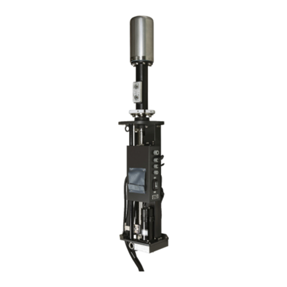
- Page 47 Diagram 1.5. Exterior view of the NKF-2800 hoisting device 1-11 1 Overview of the equipment...
-
Page 48: Overall System Diagram
Overall system diagram Sonar system diagram••••••••••Diagram 1.6 Display NWZ-207 (19 inch LCD) Keyboard NCH-578 24VDC 3A *DPYC-2.5 Cable 5m Sub display *MVVS20/0.18X6 NWZ-207 Fish-Finder Trigger,Signal (19 inch LCD) *MVVS20/0.18X4 NET meter Trigger, 4-input RGB Cable 5m *TTYCS-1 24VDC 3A *DPYC-2.5 GPS compass or GPS Processor Rectifier *TTYCS-1... - Page 49 2 Names and Functions of Parts Contents Names and Functions of Parts ......................2-1 Names of On-screen Functions ....................2-3 2.1.1 Full screen "Information display: [OFF]" ................2-3 2.1.2 Normal screen "Information display: [ON]" ............... 2-4 2.1.3 Transducer status display ....................2-5 Names and Functions of the Keyboard ...................
-
Page 50: Names And Functions Of Parts
2 Names and Functions of Parts... -
Page 51: Names Of On-Screen Functions
Names of On-screen Functions There are two types of screen displays: full screen, "Information Display: [OFF]" (diagram 1), and normal screen, "Information Display: [ON]" (diagram 2). When shipped from the factory, the default is set to full screen. The information display shows measured data and data from external devices to help find schools of fish. -
Page 52: Normal Screen "Information Display: [On]
2.1.2 Normal screen "Information display: [ON]" Diagram 2. Normal screen "Information display: [ON]" *1: To display this, you need the sensors for direction, position, ship's speed, water temperature, and depth. *2: You can select the ship's speed sensor. *3: There are three types of direction displays: relative, north direction, and relative + north direction. Refer to section 6.6.1.5 *4: A maximum of eight MULTI knobs can be registered. -
Page 53: Transducer Status Display
2.1.3 Transducer status display Status display area The storage status is shown in green. Outline of the status display area Transducer position display area Both of the storage status switches are shown in green. Example of transducer status display Operation status Extension Extension Storing... - Page 54 Example of status display when an abnormality occurs Condition ① Power is ② Power is ③ Power is ④ When turned on turned on turned on extending/retra cting Display example Upper = Retraction limit Lower = Extension limit Explanation of Retraction limit Retraction limit Retraction limit...
-
Page 55: Names And Functions Of The Keyboard
Names and Functions of the Keyboard Diagram 2. Controls 2 Names and Functions of Parts... - Page 56 ① [POWER] key Use this key when the power is off to turn the power on. <Power off> Press and hold the [POWER] key and the [PANEL] key at the same time for about one second. When you hear the confirmation beep, release your fingers from the keys.
- Page 57 ⑧ [Tilt angle] knob You can change the tilt angle with this knob. You can set the width and center when set to automatic. The tilt angle locks if you press and hold this key. To release the lock, press and hold the [Tilt angle] key again. ⑨...
- Page 58 ⑰ [RANGE LINK/3] key Press this key to switch between linked and not linked operations. Use the number [3] key, while the menu is open, to do operations. ⑱ [MEMORY/4] key Takes a screenshot of the current screen. Only one screen can be saved. The memory is deleted when the power is turned off. If you want to keep a screenshot, you can insert a CF card and save the screenshot there.
- Page 59 Press and hold the key to end tilt angle tracking. Marks that have been released change to Marks are released if they go off screen. If you press the □ mark again during tilt angle tracking, the previous mark is deleted and tilt angle tracking is released.
- Page 60 Also, by pressing and holding this key, the current display becomes off centered. If the cursor is within the range edge, even when centered, the position of the cursor becomes off centered. However, it moves a distance of 2/3 of the largest range ring. With the menu settings, you can switch the "CURSOR POSITION"...
- Page 61 Refer to the list of menus section for details about keys that can be registered as user keys. ㉘ [MULTI] (multiple function) knob Turn this knob to the right (clockwise) while an item is selected in an open menu to move the selected item to the bottom.
- Page 62 ㉜ [ENT] key Use this key to set menu selections or numbers that have been input. ㉝ [CNCL/INFO] key Use this key to cancel the input of values and to cancel selections in menus. It operates as the [INFO] key if you press it while no menus are open. Every time you press this key, the information screen changes from displayed to hidden.
-
Page 63: Operating Procedures
3 Operating procedures Contents Operating procedures ........................3-1 Work flow ..........................3-3 3.1.1 Turning on the power and extending the transducer............3-4 3.1.2 Setting the image range: [RANGE], [Tilt angle], and [GAIN]..........3-6 3.1.3 Storing the transducer and turning off the power ............. 3-7 Menu Configuration........................ - Page 64 3.3.8 TRACK LINE ........................3-26 3.3.9 Sonar range setting ......................3-26 3.3.10 Stabilize .......................... 3-27 3 Operating procedures...
-
Page 65: Work Flow
Work flow Precautions ● Do not place anything on the controls. Especially do not put anything hot on the controls, as it may deform them. ● Do not hit the controls, trackball, or knobs. Doing so may damage them. Turning on the power and extending the transducer Setting the image range Storing the transducer and turning off the power The various operations are explained next. - Page 66 3.1.1 Turning on the power and extending the transducer Precautions ● Wait about two seconds after turning off the power before turning the power back on. ● Confirm that the ship's speed is under 15 knots and that the depth of the water is at least 3 meters before you press the [FALL] key.
- Page 67 Precautions ● To prevent accidental operations, it does not extend if the button is pressed only briefly. ● The storage (up) operation starts after the [SHED] button is pressed and then released. Stopping extension/storage operations The sonar's hoisting device cannot be stopped while extending or storing. 3 Operating procedures...
-
Page 68: Setting The Image Range: [Range], [Tilt Angle], And [Gain]
3.1.2 Setting the image range: [RANGE], [Tilt angle], and [GAIN] 1. Press the [RANGE +] key and the [RANGE -] key to change the scan range. Press the [RANGE +] key to increase the range. Press the [RANGE -] key to decrease the range. The range can be switched between 16 ranges. -
Page 69: Storing The Transducer And Turning Off The Power
3.1.3 Storing the transducer and turning off the power 1. Press the [SHED] key. The hoisting mark appears on the screen while the hoisting device buzzer buzzes for five seconds, after which the transducer is stored (raised). The hoisting mark turns green and the status display area flashes. -
Page 70: Menu Configuration
Menu Configuration The sonar has many functions that are not on the controls that you can use by using the menu settings. You can improve the functionality of the sonar by setting it according to what you want to do. The following is a list of the items that make up the menu. - Page 71 Menu screen Item names Top menu Menu items Item values Menu items consist of item names (left side) and item values (right side). Each menu item is assigned a function that is executed when the item is selected. The types of functions are shown below.
- Page 72 Menu items Shows the items that can be selected in the menu. Menu items consist of a name "Item name" and a value that is set "Item value". Item value Item name Example of menu item before selection The currently selected item is highlighted. The assigned function is called up by setting it. Example of menu item when selected Some operations cannot be done until all conditions have been met, depending on the items selected for the menu item.
- Page 73 The item displayed and operation that is selected are different depending on the type of item. The types of items and their operations are shown below. Moving between menus (accessing menus up or down the hierarchy and switching menu pages) Selecting an item moves you to a submenu or returns you to the menu from which you accessed it.
- Page 74 Selecting pulldown lists A list of selectable items is displayed if this item is selected. Selecting an item from the list opens a pull down list into which entries can be made. The currently selected value and a " " indicating it is possible to make an entry on the pull down list appear.
- Page 75 Input screen example Time setting input screen Range setting input screen Color setting input screen 3-13 3 Operating procedures...
-
Page 76: Basic Menu Operations
3.2.2 Basic Menu Operations The menu can be operated in the following ways. ● The MULTI knob can be used to select items and increase or decrease values. ● The number keys from [0] to [9] can be used to select items and input values. ●... -
Page 77: Selecting Items
3.2.3 Selecting Items You can use the number keys, arrow keys, MULTI knob , or cursor (trackball) to select items. Selecting items with the MULTI knob Press the [MENU] key and, while the menu is displayed, rotate the MULTI knob to highlight and move through the items. - Page 78 Instead of pressing the [MULTI] key, you can do the same operation, by pressing the [ENT] key, if the cursor has not been moved. The following is an example of inputting changes to numerical values that are set from pulse length selection. Press the [MENU] key to display the menus.
- Page 79 Selecting items with the cursor (trackball) Press the [MENU] key to open the "Menu", and align the cursor with the item to select to highlight the item. Press the [ENT] key to set the item. To select a value or item that you want to select from a pull down list, use the same procedure as in step (1) to select it and set it.
- Page 80 Selecting items with the number keys Press the [MENU] key and, while the "Menu" is open, press the number key that corresponds to the item number to select and set at the same time. A pull down list opens, depending on the item. If you press the number key for the selected value or item number when a pulldown list is displayed, the selected item is set, the pulldown list closes, and the selected value is displayed.
- Page 81 Selecting items with the arrow keys While a "Menu" is open, press the [◀] or [▶] button to select, highlight, and move an item. Move to the item you want, press the [ENT] key to set the item. The [◀] key moves to the previous item (upper) and the [▶] key moves to the next (lower) item.
-
Page 82: Entering Values
3.2.4 Entering values The menu items in which numbers are entered are highlighted when they are in the number input mode. To input numbers, you can use the number keys, arrow keys, or MULTI knob. The number input mode is indicated by highlighting, as in the following example, which shows the item name and the item value. - Page 83 Inputting numbers with the number keys The number keys from [0] to [9] can be used to input values in value input mode while a "Menu" is open. While value input mode is on, pressing a number key reflects the changed value in the item.
- Page 84 For values that include a decimal point, always input to the value below the decimal point, because the decimal place is in a fixed position. Example: To change a 000.0 setting to 123.0 in a 4-digit input. Display [ENT] key (set value) Initial status 000.0...
-
Page 85: Getting Started
Getting Started Adjusting the screen brightness 3.3.1 Operating procedure Turn the [BRILL] knob on the bottom right side of the display to the left or right to adjust the screen so it is easier to see. Press [BRILL ] to brighten the entire screen. Press [BRILL ] to dim the entire screen. -
Page 86: Adjusting The Volume (Option)
3.3.4 Adjusting the Volume (Option) Operating procedure (Speakers are options. : 6USFD00010) Turn the [VOL] knob to the left or right to adjust the volume. Turn it to the right to increase the volume and turn it to the left to decrease the volume. 3 Operating procedures 3-24... -
Page 87: Adjusting The Buzzer Sound
3.3.5 Adjusting the Buzzer Sound Operating procedure You can adjust the sound of the buzzer of the controls by pressing the [VOL] knob. Each time you press the [VOL] knob, you can adjust the buzzer's volume through five levels. Each time it is pressed it cycles as shown below. Lowest→... -
Page 88: Track Line
3.3.8 TRACK LINE Operating procedure Press the keys "8 → 6 → 2 → 5" to go to TRACK LINE settings It is possible to select from three modes, "Hide, 1 hour, and 2 hours" for the track line. Press the [MENU] key to open the menus. Turn the [MULTI] knob to move to "8. -
Page 89: Stabilize
3.3.10 Stabilize Operating procedure Press the keys "7 → 4 → 4 → 1" to go to STABILIZE settings This sonar has an omni-directional stabilizer function. You can set the stabilizer function to "ON" or "OFF". It is normally set to "ON". Press the [MENU] key to open the menus. - Page 90 3 Operating procedures 3-28...
-
Page 91: Operations
4 Operations Contents Operations ............................4-1 Operations..........................4-3 4.1.1 Tilt angle ........................... 4-3 4.1.2 Automatic Tilt Angle Settings .................... 4-4 4.1.3 Manual Sound Detection ....................4-5 4.1.4 Automatic Sound Detection ....................4-5 4.1.5 Transmission pulse repetition rate ................... 4-7 4.1.6 Cursor Movements and Operations ................. - Page 92 Registration ..........................4-18 4.3.1 Registering a user menu [1 to 6] ..................4-18 4.3.2 Registering the user defined keys [F1], [F2], and [F3] ........... 4-20 4.3.3 Registering the MULTI knob [1 to 6] ................4-21 4 Operations...
-
Page 93: Operations
4.1 Operations 4.1.1 Tilt angle Operating Procedure You can change the tilt angle from -5° to 60° by turning the [TILT ANGLE] knob. Turn the knob to the right to make the tilt angle deeper and turn it to the left to make it shallower. Use this to adjust the tilt angle according to the depth at which the schools of fish are distributed and the Shallower... -
Page 94: Automatic Tilt Angle Settings
4.1.2 Automatic Tilt Angle Settings Operating Procedure When doing manual tilt angle, the tilt angle display shows 0°. Manual Tilt Angle Settings You can change the tilt angle automatically by pressing the [TILT AUTO] key. Press the [TILT AUTO] key to switch to "AUTO TILT". Automatic Tilt Angle Settings Then press the [TILT AUTO] key again to change to "MANUAL TILT". -
Page 95: Manual Sound Detection
4.1.3 Manual Sound Detection You can listen to the sound of the image that is shown on the screen. It is possible to understand whether or not a school of fish exists, and its density, from the sound, without looking at the image. Operating Procedure To align the direction at which you want to hear the audio, turn the [DIRECTION] knob on the controls... - Page 96 Example of setting automatic sound detection Sound detection Sound detection direction Press the [AZIMT AUTO] key. direction moves automatically Shows the Direction range moves automatically Example of automatic sound detection range settings Automatic sound detection Press the [DIRECTION] knob to maximize direction is moving the automatic sound detection range Sound detection direction...
-
Page 97: Transmission Pulse Repetition Rate
4.1.5 Transmission pulse repetition rate If there are many ships around, you may receive interference from other sonars or fish finders that are using the same frequency as you. In addition, if you are using a short range setting, the previous transmission image may, on rare occasions, appear on the screen. -
Page 98: Cursor Movements And Operations
Changes to the transmission pulse repetition rate are done in two ways: directly on the controls or by opening the menus and doing the settings. Operating Procedure Procedure to change the transmission pulse repetition rate by using the [ ] and [ ] keys on the ◄... -
Page 99: Off Center Display
The cursor returns to its normal shape when [MENU] closes or the cursor position moves out of the [MENU] display area. If you move the cursor position to within the [MENU] display, the color of the menu item at the cursor's position changes to the selected color. - Page 100 Maximum off center position Position B When you long-press the [OFF CENT] key, your own ship's position moves to the maximum off center position, where it intersects a straight line between the cursor position and the center position of the screen cursor position, if the cursor position is in the "B position". ●...
- Page 101 ● Off center move to cursor position Operating Procedure Press the keys "8 4" to go to OFF CENTER settings → → Press the [Menu] key. Turn the [MULTI] knob to move to "8. OPERATION" and press the [MULTI] knob to open the submenu. Turn the [MULTI] knob to move to "2.
- Page 102 ● "Off center move to registered position" Operating Procedure Press the keys "8 4" to go to OFF CENTER settings → → Press the [MENU] key to open the menus. Turn the [MULTI] knob to move to "8. OPERATION" and press the [MULTI] knob to open the submenu. Turn the [MULTI] knob to move to "2.
-
Page 103: Operating And Clearing Alarms
4.1.8 Operating and Clearing Alarms In the menu settings, you can turn the alarm on and specify the ANGLE, DISTANCE, AREA SIZE, LEVEL, AMOUNT, and LOST COUNT on the screen display so that if a school of fish is detected within this area an alarm sounds. -
Page 104: Automatic Tracking Operation
4.1.9 Automatic Tracking Operation [ Operating Procedure If you put the cursor on the image of a school of fish and then press the [ ] key twice, the direction, tilt angle, and distance from your own ship, at the time the school of fish were marked, are used to calculate the tracking function operations. -
Page 105: Split Display
4.2 Split Display By pressing the [MODE] key, you can display the fish finder images and the sound detection images on the screen. The sound detection display and fish finder display are disabled in the initial settings. To enable them, do the settings for each one. -
Page 106: Fish Finder Display
"1. AUDIO" has been set to enabled. Press the [MENU] key to close "MENU". The initial values set for the split mode settings are "PARTITION SIZE = Small" and "SPLIT POSITION = Lower left" The initial values for the display settings are "LENGTH SCALE = Show", "SCROLL = STOP", "SCROLL = Vertical", and "AUDIO STEP = 3". - Page 107 Fish finder images vary depending on the number of fish finders that are connected. To display the fish finder, settings other than just "On" and "Off" are required. The setting items that must be adjusted after displaying the fish finder are "TRIGGER", "RANGE SETTING", "GAIN", "F/F CLUTTER", "SHIFT", FISH FINDER ADC", "FISH FINDER STC", "FISH FINDER INTERFERENCE", and "STC CURVE".
-
Page 108: Registration
Split screen When lower left Split screen size is small is selected size is large When lower When lower left is selected right is selected Example: Two frequencies, display is Example: One frequency connection, large in lower left lower left and lower right display Example: One Vertical scroll Example: Screen... - Page 109 Operating Procedure This section explains the operations for the [MULTI] knob. Example: Explains the procedure for registering the "RECEIVE" menu to a user menu. Press the [MENU] key to open the menus. Turn the [MULTI] knob to select "7. FISH IMAGE" and press the [MULTI] knob to open the submenu.
-
Page 110: Registering The User Defined Keys [F1], [F2], And [F3]
4.3.2 Registering the user defined keys [F1], [F2], and [F3] You can add menu items that you want to use to the [F1], [F2], and [F3] keys on the controls. There are 15 types of menu items that you can register to the user defined keys. Refer to the list of other menu items regarding the items that can be registered. -
Page 111: Registering The Multi Knob [1 To 6]
4.3.3 Registering the MULTI knob [1 to 6] By registering menu items to the [MULTI] knob, you can, while [MENU] is closed, change items and setting values of menu items that have been registered by pressing the [MULTI] knob, without opening [MENU]. - Page 112 Turn the [MULTI] knob to move to "1. MULTI No.1" and press the [MULTI] knob to set "1. CLUTTER". (Registration is not yet complete) Turn the [MULTI] knob to move to "9. SET". Press the [MULTI] knob to complete registration. Press [MENU] to close the menu.
- Page 113 Press the [MULTI] knob to set "STC LEVEL" to "2. MULTI No. 2". (Registration is not yet complete) Turn the [MULTI] knob to move to "9. SET" and press the [MULTI] knob to complete registration. Press the [MENU] key to close the menu. Registration is complete if when you turn the [MULTI] knob, while "MENU"...
- Page 114 Turn the [MULTI] knob to adjust the image, as you are viewing it, to the optimum value. When it is at its optimum value, press the [MULTI] knob. If you do not set it, the value in the center of the screen disappears [MULTI]...
-
Page 115: Adjusting How Images Appear
5 Adjusting How Images Appear Contents Adjusting How Images Appear ......................5-1 Appearance of Images ......................5-3 5.1.1 Tilt Angle and the Appearance of the Sea Floor ............... 5-3 5.1.2 Tilt Angle and the Appearance of Images of Schools of Fish........... 5-4 5.1.3 Images and Effects of Own Ship's Wake and the Wakes of Other Ships ...... - Page 116 5.2.3 Settings for Signal Processing ..................5-14 5.2.3.1 Settings for Interference ..................5-14 5.2.3.2 Settings for Signal Processing P ................5-15 5.2.3.3 Settings for Signal Processing R ................5-15 5.2.3.4 Settings for Signal Processing D ................5-16 5.2.3.5 Settings for Oscillation Processing C ..............5-16 5.2.4 Technological Settings ....................
-
Page 117: Appearance Of Images
5.1 Appearance of Images 5.1.1 Tilt Angle and the Appearance of the Sea Floor 1) Characteristics of the image of the sea floor when the tilt angle is between 10° and 15° The sea floor is displayed in a wide ring shape when the depth is shallow or when the sea floor is flat. The width of the sea floor is displayed as wide and the strength of the color of the sea floor is displayed as weak. -
Page 118: Tilt Angle And The Appearance Of Images Of Schools Of Fish
5.1.2 Tilt Angle and the Appearance of Images of Schools of Fish 1) Appearance of schools of fish that are at the surface of the sea. Searches at a tilt angle near 0° to 10°. School of fish Tilt angle Reflection of the surface of the sea, clutter near the surface of the sea, etc. -
Page 119: Images And Effects Of Own Ship's Wake And The Wakes Of Other Ships
3) Tilt Angle and the Appearance of the Reflection of the Sea Surface When searching for schools of fish at the surface, depending on inclement weather and the condition of the sea, detecting an image of a school of fish may become difficult due to the influence of the reflection of the sea surface. -
Page 120: Settings For Fish Echoes
5.2 Settings for Fish Echoes The fish image setting is a menu for setting the signal process and adjusting the transmitter/receiver unit. Normally, use the standard setting values. The five types of standard settings, A through E, from the [IMAGE] knob are also included. Before changing the fish image setting menu, we recommend turning the [IMAGE] knob and finding the setting values that fit your work. -
Page 121: Stc Level
5.2.1.2 STC LEVEL You can suppress short distance noise. Press the keys "7 → 1 → 2" to go to STC LEVEL settings Operating Procedure Press the [MENU] key to display the menus. Turn the [MULTI] knob to move to "7. FISH IMAGE". Press the [MULTI] knob to open the submenu. -
Page 122: Settings For The Vertical Beam
Turn the [MULTI] knob to change and adjust this value. The horizontal beam is normally used at 5. The width of the horizontal beam becomes narrower by increasing this value. It becomes wider by decreasing this value. Increase this value if you want to increase the sharpness of horizontal images. -
Page 123: Transmission Settings
5.2.2 Transmission Settings The "TX" menu is a submenu to be used to eliminate interference from other ships, suppress reverberation, and suppress false echoes caused by detection performance and shallow sea floors. 5.2.2.1 Transmission Power Settings You can adjust the power of transmissions. For normal operations, always use a maximum value of 10. -
Page 124: Settings For The Pulse Length
Press the keys "7 → 2 → 1" to go to TX POWER settings Operating Procedure Press the [MENU] key to display the menus. Turn the [MULTI] knob to move to "7. FISH IMAGE". Press the [MULTI] knob to open the submenu. Turn the [MULTI] knob to move to "2. -
Page 125: Transmission Mode Settings
Press the keys "7 → 2 → 2" to go to PULSE LENGTH Operating Procedure settings Press the [MENU] key to display the menus. Turn the [MULTI] knob to move to "7. FISH IMAGE". Press the [MULTI] knob to open the submenu. -
Page 126: Settings For Shading
beam is widened. Press the keys "7 → 2 → 4" to go to V BEAM settings Operating Procedure Press the [MENU] key to display the menus. Turn the [MULTI] knob to move to "7. FISH IMAGE". Press the [MULTI] knob to open the submenu. Turn the [MULTI] knob to move to "2. -
Page 127: Settings For The Transmission Pulse Repetition Rate
Press the [MULTI] knob to open the settings menu. The initial value is set to 0. You can set the values from 0 to 3, in steps of 1, by turning the [MULTI] knob. 5.2.2.6 Settings for the Transmission Pulse Repetition Rate If there are many ships around, you may receive interference from other sonars or fish finders that are using the same frequency as you. -
Page 128: Settings For Signal Processing
5.2.3 Settings for Signal Processing Signal Processing is the menu that sets the four types of correlation processing for sonar images. You can make adjustments so that schools of fish are easier to see by changing the settings according to the types of fish, fishing method, and condition of the sea. 5.2.3.1 Settings for Interference You can eliminate interference from your own ship's ultrasound equipment and interference from the sonars and various ultrasound equipment of other ships. -
Page 129: Settings For Signal Processing P
5.2.3.2 Settings for Signal Processing P Process the correlations of received signals that correspond to the entire screen for each transmission. Sensitivity to rapidly moving fish decreases if you increase this value. You can display stable images for large schools. Make adjustments according to the types of fish, fishing method, condition of the sea, port congestion, etc. -
Page 130: Settings For Signal Processing D
5.2.3.4 Settings for Signal Processing D Process the correlation of received signals for the circumferential distance. Although stable images can be obtained for the circumferential distance by increasing this value, the ability to discern small schools of fish decreases. Make adjustments according to the types of fish, fishing method, condition of the sea, port congestion, etc. -
Page 131: Technological Settings
5.2.4 Technological Settings This is a menu item for doing detailed technological settings for the transponder and the transmitter/receiver unit. Normally, use the standard setting values the way they are. This is mainly a setting for the service representative. Press the keys "7 → 4" to go to TECHNOLOG SET Operating Procedure settings Press the [MENU] key to display the menus. -
Page 132: Min Vr
5.2.4.1.1 MIN VR This is a menu item for doing settings for MIN VR for the volume of sensitivity. Normally, use the standard setting values the way they are. Press the keys "7 → 4 → 1 → 1" to go to MIN VR Operating Procedure settings In the "TVG"... -
Page 133: Abfg
5.2.4.1.3 ABFG Always use ABFG at 8. Press the keys "7 → 4 → 1 → 3" to go to ABFG settings Operating Procedure In the "TVG" menu, turn the [MULTI] knob to move to [3. ABFG]. Press the [MULTI] knob to open the value input key menu. -
Page 134: Rx Vr
5.2.4.1.5 RX VR Normally, use the initial setting of 255 as it is. Press the keys "7 → 4 → 1 → 5" to go to RX VR settings Operating Procedure In the "TVG" menu, turn the [MULTI] knob to move to "5. -
Page 135: Settings For Time Varied Gain (Long Distance)
5.2.4.1.7 Settings for Time Varied Gain (Long Distance) This is a menu for setting the slope of the ABS ATT curve + the diffusion loss over long distances. Press the keys "7 → 4 → 1 → 7" to go to TVG (FAR) Operating Procedure settings In the [TVG] menu, turn the [MULTI] knob to move to... -
Page 136: Settings For The Automatic Gain Control Mode
5.2.4.2.1 Settings for the Automatic Gain Control Mode This is a menu item for setting the constants and various methods to control the AGC. Press the keys "7 → 4 → 2 → 1" to go to AGC MODE Operating Procedure settings In the [AGC] menu, turn the [MULTI] knob to move to [1. -
Page 137: Scan Agc Level
5.2.4.2.3 SCAN AGC LEVEL This is a menu item for doing settings for SCAN AGC LEVEL (circumferential direction of AGC). Press the keys "7 → 4 → 2 → 3" to go to SCAN AGC Operating Procedure LEVEL settings In the "AGC" menu, turn the [MULTI] knob to move to [3. -
Page 138: Fast Agc On/Off
5.2.4.2.5 FAST AGC ON/OFF This is a menu item for doing ON/OFF settings for FAST AGC. This is for AGC that promptly and effectively suppresses the excessive signals that are input from various directions. Press the keys "7 → 4 → 2 → 5" to go to FAST AGC Operating Procedure ON/OFF settings In the [AGC] menu, turn the [MULTI] knob to move to... -
Page 139: Fast Agc Level
5.2.4.2.7 FAST AGC LEVEL This is a menu item for doing level settings for FAST AGC. Press the keys "7 → 4 → 2 → 7" to go to FAST AGC Operating Procedure LEVEL settings In the "AGC" menu, turn the [MULTI] knob to move to [7. -
Page 140: Settings For Signal Reception Clutter
5.2.4.3.1 Settings for Signal Reception Clutter This is a menu item that sets the clutter within the receiver. Press the keys "7 → 4 → 3 → 2" to go to RX CLUTTER Operating Procedure settings In the "RECEIVE" menu, turn the [MULTI] knob to move to [2. -
Page 141: Stc Range
5.2.4.3.3 STC RANGE This is a menu item that sets the distance of the STC and TVG (MID) changeover points. Press the keys "7 → 4 → 3 → 4" to go to STC RANGE Operating Procedure settings In the "RECEIVE" menu, turn the [MULTI] knob to move to [4. -
Page 142: Settings For Signal Transmission And Reception Calibration
5.2.4.4 Settings for Signal Transmission and Reception Calibration This is a menu item for doing settings for stabilize and the basic features of the ultrasonic sound waves. Press the keys "7 → 4 → 4" to go to TX/RX CALIB Operating Procedure settings Move to the "TECHNOLOG SET"... -
Page 143: Abs Att
5.2.4.4.2 ABS ATT This is a menu item that sets the ABS ATT of the frequency to be used. Press the keys "7 → 4 → 4 → 2" to go to ABS ATT Operating Procedure settings In the "TX/RX CALIB" menu, turn the [MULTI] knob to move to [2. -
Page 144: Settings For Gain Range Sw
5.2.4.4.4 Settings for Gain Range SW This is a menu item that sets the gain range switch of the receiver. Press the keys "7 → 4 → 4 → 4" to go to GAIN RANGE Operating Procedure SW settings In the "TX/RX CALIB" menu, turn the [MULTI] knob to move to [4. -
Page 145: Adc Curve Settings
5.2.4.5 ADC Curve Settings This is a menu item that sets the curve at which to convert to color when displaying the received signals on the screen. Press the keys "7 → 4 → 5" to go to ADC settings Operating Procedure Move to the "TECHNOLOG SET"... -
Page 146: Settings For The Image Sw Function
5.2.5 Settings for the Image SW Function Turning the [IMAGE] knob registers a setting between A and E. Settings A through E change the internal settings values, as seen in the following table. Refer to the following table when using this equipment. Echoes Assumed use Pulse... - Page 147 Before pressing After pressed Turning the [IMAGE] knob while the value is displayed in red changes the value. Increasing this value increases noise and decreasing it decreases noise. 5-33 5 Adjusting How Images Appear...
- Page 148 5 Adjusting How Images Appear 5-34...
- Page 149 6 Operation Settings Contents Operation Settings .......................... 6-1 Operation Modes ........................6-3 6.1.1 AUTO TX .......................... 6-3 6.1.2 TX ............................. 6-4 6.1.3 Screen Memory Card ....................... 6-4 6.1.4 Alarms ..........................6-9 6.1.5 Setting Card ........................6-15 6.1.6 Automatic Storage Function ................... 6-18 6.1.7 Operation Settings ......................
- Page 150 6.3.3 Deleting Marks ......................6-32 6.3.4 Deleting Buoy Marks ...................... 6-33 6.3.5 Deleting Fish School Quantity Marks ................6-34 6.3.6 Deleting All Marks ......................6-35 Information Display Settings ....................6-36 6.4.1 Information Display Format .................... 6-38 6.4.2 Position of Display ......................6-42 6.4.3 Priority of Displays ......................
-
Page 151: Operation Modes
6.1 Operation Modes This section explains the operation mode settings, such as setting transmission to "On" or "Off", recording screenshots, alarms, reading saved setting values, automatic tilt angle, adjustments to the speed of the cursor (which is used for operations), the amount of change to the tilt angle, and other settings and adjustments. -
Page 152: Screen Memory Card
6.1.2 TX Precautions Always confirm that the hoisting device is extended before turning this setting "On". Do not turn it "On" if the hoisting device is stored. Doing so could damage both the transmitter and the transducer. If the "AUTO TX" menu is "On", the menu is masked (cannot be set). You can set this to "On"... - Page 153 Press the keys "8 → 1 → 3 → 1" to go to WRITE FILE Operating Procedure settings Press the [MENU] key to open the menu. Turn the [MULTI] knob to move to "OPERATION". Press the [MULTI] knob to open the submenu. Turn the [MULTI] knob to move to "MODE SET".
- Page 154 6.1.3.2 READ FILE You can display the screen data that you saved to the memory card. Press the keys "8 → 1 → 3 → 2" to go to READ FILE Operating Procedure settings Press the [MENU] key to open the menu. Turn the [MULTI] knob to move to "OPERATION".
- Page 155 6.1.3.3 Deleting Files You can delete the screen data that you saved to the memory card. Press the keys "8 → 1 → 3 → 3" to go to DELETE FILE Operating Procedure settings Press the [MENU] key to open the menu. Turn the [MULTI] knob to move to "OPERATION".
- Page 156 6.1.3.4 Replaying Screens Screens are not displayed as is, even if you replay them from the screen memory or the from the screen memory on the card. To display them, you need to set the replay display settings to "On". Press the keys "8 →...
-
Page 157: Alarms
6.1.4 Alarms In this section we explain how to turn alarms "On" and "Off", as well as how to set "ANGLE", "DISTANCE", "AREA SIZE", "LEVEL", and "LOST COUNT". Press the keys "8 → 1 → 4" to go to ALARM settings Operating Procedure Press the [MENU] key to open the menu. -
Page 158: Angle Settings
6.1.4.2 Angle Settings This menu is for changing the detection angle of the alarm range. You can select from three settings: 30°, 90°, and 180°. The initial value is set to "90°". Press the keys "8 → 1 → 4 → 2" to go to ANGLE Operating Procedure settings Use the [MULTI] knob to open the submenu for... -
Page 159: Distance Settings
6.1.4.3 Distance Settings This section explains how to set the detection distance for the alarm range. You can set the distance from 50 m to 5000 m in 1 m increments. Press the keys "8 → 1 → 4 → 3" to go to DISTANCE Operating Procedure settings Use the [MULTI] knob to open the submenu for... -
Page 160: Area Size Settings
6.1.4.4 Area Size Settings You can set the detection area for the distance direction of the alarm range. You can select a detection area from three types: "Small", "Medium", and "Large". Press the keys "8 → 1 → 4 → 4" to go to AREA SIZE Operating Procedure settings Use the [MULTI] knob to open the submenu for... -
Page 161: Level Settings
6.1.4.5 Level Settings This section explains how to set the minimum level that is detected as an alarm. The initial value is set to "15". If you set the alarm level too low, static noise may cause the alarm to operate. Press the keys "8 →... -
Page 162: Lost Count Settings
6.1.4.7 Lost Count Settings The sonar is equipped with a function that automatically cancels alarms depending on the number of times that the amount falls below the detection level after an alarm occurs. This function operates according to the "LOST COUNT" settings. This function stops if set to "CONTINUOUS", so that once an alarm occurs the alarm continues, unless it is cancelled with the [CLR] key. -
Page 163: Setting Card
6.1.5 Setting Card You can record items that are set in the menus and the fish image settings to a compact flash card. These settings can be read and the memories can be managed (deleted). (Precaution: Check with your retailer or service representative before purchase.) Press the keys "8 →... -
Page 164: Reading Setting Values
6.1.5.2 Reading Setting Values You can record values, that have been set to match a type of fish and a fishing method that were done while you were fishing, to the card. You can also record the current setting values to a card and recover them by reading them from the card if you happen to accidently change the current settings and you cannot change them back. -
Page 165: Formatting Cards
Press the keys "8 → 1 → 5 → 3" to go to DELETE settings Operating Procedure Open the submenu for "5. SETTING CARD", the same as in the previous section. Turn the [MULTI] knob to select "3. SETTING DEL FILE". -
Page 166: Automatic Storage Function
6.1.6 Automatic Storage Function This sonar is equipped with an automatic storage function. When the ship reaches a set speed, the transducer is stored automatically. On this menu, you can enable automatic storage and set the ship's speed at which automatic storage is done. The initial value is set to "16 knots". The ship's speed sensor is required to use the automatic storage function. - Page 167 1. If the ship's speed exceeds 16 knots, the ship's speed display turns red. 2. "UP" appears in the middle of the screen. At the same time, the hoisting device buzzer starts sounding and storage operations start after two seconds. As soon as the buzzer sounds, move away from the hoisting device.
-
Page 168: Operation Settings
6.1.7 Operation Settings You can set the pointer (cursor mark) distance of motion and the speed of the dial operations. Press the keys "8 → 1 → 7" to go to OPERATION SET Operating Procedure settings Press the [MENU] key to open the menu. Turn the [MULTI] knob to select "8. -
Page 169: Knob Operations
6.1.7.2 Knob Operations This section explains how to set the operating speeds of the various types of knobs. The knobs, MULTI, VOL, FISH IMAGE, GAIN, and AUDIO DIRECTION, are all changed with the same shared setting. The initial value is set to "1. LOW". It is normally set to the initial value. Press the keys "8 →... -
Page 170: Tilt Step Settings
6.1.8.1 Tilt Step Settings This section explains the tilt step, which is the tilt steps (changes in angle) that are applied for every transmission when automatic stepping is set. Press the keys "8 → 1 → 8 → 1" to go to TILT STEP Operating Procedure settings Turn the [MULTI] knob to select "1. -
Page 171: Display Mode Settings
6.2 Display Mode Settings This section explains settings such as the off center, split settings, RM mode, and whether to hide or show information. Press the keys "8 → 2" to go to DISPLAY MODE Operating Procedure settings Press the [MENU] key to open the menu. Turn the [MULTI] knob to select "8. - Page 172 In the information display area, you can split the area to show 3 of the following 5 items, from 2 to 6. If the information is displayed, "1. SHIP INFO" is fixed in the top position. The user cannot change it. Area Middle Bottom...
- Page 173 6.2.2 RM You can set your own ship's heading direction (head-up) or north at the top (north-up) of the sonar image screen. Press the keys "8 → 2 → 2" to go to RM settings Operating Procedure Turn the [MULTI] key to select "2. RM". Press the [MULTI] knob to select "1.
-
Page 174: Split Display
6.2.3 Split Display You can set the system to show the audio image or the fish finder image on the sonar image screen. Press the keys "8 → 2 → 3" to go to SPLIT DISPLAY Operating Procedure settings Turn the [MULTI] key to select "3. SPLIT DISPLAY". Press the [MULTI] knob to display the submenu, select either "1. -
Page 175: Fish Finder
6.2.3.2 Fish finder If the fish finder is connected, you can also display the fish finder image on the screen by setting the split display setting to "2. ON". Press the keys "8 → 2 → 3 → 2" to go to FISH FINDER Operating Procedure settings Turn the [MULTI] key to select "2. -
Page 176: Off Center Function
6.2.4 Off Center Function You can move your own ship's position from the center of the screen to a position that is up to 3/4 of the maximum setting range. There are three types of off center settings. You can set these operations by long pressing the [OFF CENT] key while this menu is open. -
Page 177: Deleting Marks
6.3 Deleting Marks This menu is for deleting track lines and the various marks from the sonar screen. Precaution) To delete marks, except the track lines, one at a time, align the cursor with the mark and press the same type of mark again. It is useful to register a function key, F1 to F3, to delete marks that you often use. -
Page 178: Deleting Track Lines
6.3.1 Deleting Track Lines This item is set when you delete track lines. Press the keys "8 → 3 → 1" to go to DELETE TRACK Operating Procedure settings Follow the operations for deleting marks. Open the "DELETE MARK" menu. Turn the [MULTI] knob to select "1. -
Page 179: Deleting Marks
6.3.2 Deleting Marks The fish school marks are used, by placing multiple marks, to measure the speed and direction in which the fish school is moving. After following one fish school, you need to delete the first fish school once to measure the ... -
Page 180: Deleting Marks
6.3.3 Deleting Marks X marks are what event marks are called for short. You can place a maximum of 10 marks. The first 5 marks show the distance and direction from your own ship. With this menu, you can delete the X marks. Press the keys "8 →... -
Page 181: Deleting Buoy Marks
6.3.4 Deleting Buoy Marks This menu is for deleting all the buoy marks. Press the keys "8 → 3 → 4" to go to DELETE BUOY Operating Procedure settings Follow the operations for deleting marks. Open the "DELETE MARK" menu. Turn the [MULTI] knob to select "4. -
Page 182: Deleting Fish School Quantity Marks
6.3.5 Deleting Fish School Quantity Marks This menu is for deleting fish school quantity marks. Press the keys "8 → 3 → 5" to go to DELETE FISH Operating Procedure SCHOOL MARKS settings Follow the operations for deleting marks. Open the "DELETE MARK" menu. Turn the [MULTI] knob to select "5. -
Page 183: Deleting All Marks
6.3.6 Deleting All Marks All the marks are deleted, except for track lines. Use this when you want to delete everything at the same time. Press the keys "8 → 3 → 6" to go to DELETE ALL Operating Procedure settings Follow the operations for deleting marks. -
Page 184: Information Display Settings
6.4 Information Display Settings This menu is for setting the display settings: ship information, fish school information, water temperature graph, current, and net depth. Also, in regard to the event mark information display, whether to show or hide the display, display position, and priority position. Press the keys "8 →... - Page 185 The following images are examples of the information that is displayed. Own ship's information Fish School Information Water Temperature Graph Current Net Depth Event Marks 6-37 6 Operation Settings...
-
Page 186: Information Display Format
6.4.1 Information Display Format This menu is for setting whether to hide, show, or automatically show: own ship's information, fish school information, water temperature graphs, currents, net depth, and event marks. If the information displays are hidden, you can press the [Delete/Information] key on the controls to display them. -
Page 187: Own Ship's Information
6.4.1.1 Own Ship's Information This section explains how to set your own ship's information to be hidden, displayed, or automatically displayed. Press the keys "8 → 4 → 1 → 1" to go to SHIP INFO Operation Procedure settings Follow the menu operations for status display to display the "STATUS"... -
Page 188: Water Temperature Graph
6.4.1.3 Water Temperature Graph This section explains how to set the water temperature graph to be hidden, displayed, or automatically displayed. You can display a water temperature graph with these settings. Precaution) You need to connect the sensors to display the water temperature and water depth. -
Page 189: Net Depth
6.4.1.5 Net Depth This section explains how to set net depth to be hidden, displayed, or automatically displayed. Precaution) You need to connect the sensors to display the net depth. Press the keys "8 → 4 → 1 → 5" to go to NET INFO Operating Procedure settings Follow the menu operations for status display to... -
Page 190: Position Of Display
6.4.2 Position of Display This menu item is for setting the display position for: own ship's information, fish school information, water temperature graphs, currents, net depth, and event marks. Press the keys "8 → 4 → 2" to go to POSITION settings Operating Procedure Follow the menu operations for information display to display the "INFORMATION"... -
Page 191: Own Ship's Information
6.4.2.1 Own Ship's Information This is the menu item for setting the position to display own ship's information. Press the keys "8 → 4 → 2 → 1" to go to SHIP INFO Operation Procedure settings Follow the menu operations for position display to display the "POSITION"... -
Page 192: Current
Follow the menu operations for position display to display the "POSITION" submenu. Turn the [MULTI] knob to select "3. TEMP/DEPTH". Press the [MULTI] knob to display the pulldown menu. Turn the [MULTI] knob to select the position to display the water temperature graph. Press the [MULTI] knob to set it. -
Page 193: Event Marks
6.4.2.6 Event Marks This is the menu item for setting the position to display event marks. Press the keys "8 → 4 → 2 → 6" to go to EVENT MARK Operating Procedure settings Follow the menu operations for position display to display the "POSITION"... -
Page 194: Priority Of Displays
6.4.3 Priority of Displays This menu item is for setting the display priority for: own ship's information, fish school information, water temperature graphs, currents, net depth, and event marks. If the display positions are the same, they are displayed in order of highest priority to lowest (1 to 3). Press the keys "8 →... -
Page 195: Fish School Information
6.4.3.2 Fish School Information This is the menu item for setting the priority at which to display fish school information. Press the keys "8 → 4 → 3 → 2" to go to FISH Operation Procedure HISTOGRAM settings Follow the menu operations for priority display to display the "PRIORITY"... -
Page 196: Net Depth
Turn the [MULTI] knob to select the priority at which to display the current information. Press the [MULTI] knob to set it. The initial setting is set to "1". 6.4.3.5 Net Depth This is the menu item for setting the priority at which to display net depth. Press the keys "8 →... -
Page 197: Display Settings
6.4.4 Display Settings This menu item is for setting the display for: fish school information, water temperature graphs, currents, and net depth. Depending on the display items, you can graph numerical values or display a combination of graphs and numerical values. Press the keys "8 →... -
Page 198: Detection Area
6.4.4.1.1 Detection Area This is the menu item for setting the area of the detection area. Press the keys "8 → 4 → 4 → 1 → 1" to go to DETECT Operating Procedure AREA settings Turn the [MULTI] knob to select "1. DETECT AREA". Press the [MULTI] knob to display the pulldown menu. -
Page 199: Display Settings For The Water Temperature Graph
6.4.4.2 Display Settings for the Water Temperature Graph This is the menu item for setting the various setting values for the water temperature graph. Press the keys "8 → 4 → 4 → 2" to go to TEMP/DEPTH Operating Procedure settings Follow the menu operations for setting display to display the "SETTING"... -
Page 200: Displays
6.4.4.3 Displays This is the menu item for setting the method to display water temperature graphs. Press the keys "8 → 4 → 4 → 2 → 1" to go to Operating Procedure TEMP/DEPTH settings Turn the [MULTI] knob to select "1. TEMP/DEPTH". Press the [MULTI] knob to display the pulldown menu. -
Page 201: Display Time
6.4.4.3.1 Display time This is the menu item for setting the time to display water temperature graph. Press the keys "8 → 4 → 4 → 2 → 2" to go to TIME Operating Procedure settings Turn the [MULTI] knob to select "2. DISPLAY". Press the [MULTI] knob to display the pulldown menu. -
Page 202: Upper Limit For Water Depth
The temperatures that can be set range from -10°C to 40°C. Turn the [MULTI] knob to set an appropriate value and press the [MULTI] knob to set it. 6.4.4.3.4 Upper limit for water depth This is the menu item for setting the upper limit for water depth value for the water temperature graph. -
Page 203: Display Settings For Current
6.4.4.4 Display Settings for Current This menu item is for setting the screen configuration for the current information settings and the current graph. Press the keys "8 → 4 → 4 → 3" to go to CURRENT Operating Procedure settings Follow the menu operations for setting display to display the "SETTING"... -
Page 204: Current Range
Numerical Value Numerical Value + Net Depth Display example: Numerical Value + Graph Numerical Value Display Current Direction and Current Speed Display Current Direction + Current Speed and Current Current Speed Speed Depth Display Display Graph Current + Current Speed Numerical Value Display Net Depth Numerical Value Display... -
Page 205: Depth Range
Turn the [MULTI] knob to select a numerical value according to the fishing method and sea conditions. The initial setting is set to "2. 2NM". Select an item and press the [MULTI] knob to set it. 6.4.4.4.3 Depth Range This is the menu item for setting the values on the current measurement depth graph axis of the "Numerical Value + Graph"... -
Page 206: Display Settings For Net Depth
6.4.4.5 Display Settings for Net Depth This is the menu item for setting the configuration to display the net depth display. Press the keys "8 → 4 → 4 → 4" to go to NET settings Operating Procedure Follow the menu operations for setting display to display the "SETTING"... -
Page 207: Split Display Settings
6.5 Split Display Settings This is the menu item for setting the audio and fish finder split screen mode and the size and positions of the screens. Press the keys "8 → 5" to go to SPLIT DISPLY SET Operating Procedure settings Press the [MENU] key to display the menus. -
Page 208: Split Size
6.5.1.1 Split Size This is the menu item for setting the split size. Press the keys "8 → 5 → 1 → 1" to go to PARTITION Operating Procedure SIZE settings Turn the [MULTI] knob to select "1. PARTITION SIZE". Press the [MULTI] knob to display the pulldown menu. -
Page 209: Audio Display Settings
6.5.2 Audio Display Settings This is the menu item for setting audio steps, scroll direction, image scrolling, and whether to have a distance scale on the audio split screen. Press the keys "8 → 5 → 2" to go to AUDIO settings Operating Procedure Follow the menu operations for split display to display the "SPLIT DISPLAY"... -
Page 210: Scrolling
6.5.2.2 Scrolling This is the menu item for setting the start and stop for scrolling in the audio split screen. Press the keys "8 → 5 → 2 → 2" to go to SCROLL Operating Procedure settings Turn the [MULTI] knob to select "2. SCROLL". Press the [MULTI] knob to display the pulldown menu. -
Page 211: Audio Step Settings
6.5.2.4 Audio Step Settings This is the menu item for setting the steps when the direction knob is turned. Press the keys "8 → 5 → 2 → 4" to go to AUDIO STEP Operating Procedure settings Turn the [MULTI] knob to select "4. AUDIO STEP". Press the [MULTI] knob to display the pulldown menu. -
Page 212: Display Settings For Fish Finder
6.5.3 Display Settings for Fish Finder This is the menu item for setting the amount to scroll, the direction to scroll, and the method to split the fish finder screen. Press the keys "8 → 5 → 3" to go to FISH FINDER Operating Procedure settings Follow the menu operations for split display to display... -
Page 213: Scrolling Direction
6.5.3.2 Scrolling Direction This is the menu item for setting the direction for scrolling in the fish finder split screen. Press the keys "8 → 5 → 3 → 2" to go to SCROLL Operating Procedure settings Turn the [MULTI] knob to select "2. DIRECTION". Press the [MULTI] knob to display the pulldown menu. -
Page 214: Screen Settings
6.6 Screen Settings These are the menu items for setting the numbers that are displayed on the screen, showing/hiding marks on the screen, etc. Press the keys "8 → 6" to go to SCREEN SETTING Operating Procedure settings Press the [MENU] key to display the menus. Turn the [MULTI] knob to select "8. -
Page 215: Settings For The Display Of The Position Of Own Ship
6.6.1.1 Settings for the Display of the Position of Own Ship This is the menu item for setting whether to show or hide the display of the position of your own ship that is shown at the bottom of the screen. Press the keys "8 →... -
Page 216: Settings For The Display Of Compass Points
The initial setting value is set to "2. ON". "3. AUTO" displays your speed and course if it is received. Display example: Course: Speed, hide/show 6.6.1.3 Settings for the Display of Compass Points This is the menu item for setting whether to show or hide the display of the compass points in the form of a range ring. -
Page 217: Settings For The Display Of Direction
6.6.1.4 Settings for the Display of Direction This is the menu item for automatically setting whether the display of the direction is the course or a direction heading. Press the keys "8 → 6 → 1 → 4" to go to DIRECTION Operation Procedure settings Turn the [MULTI] knob to select "4. -
Page 218: Settings For The Display Of Water Temperature
1. Relative 2. True direction 3. Relative and true direction 6.6.1.6 Settings for the Display of Water Temperature This is the menu item for setting whether to show or hide the display for the temperature of the water, positioned at the upper right of the screen. Press the keys "8 →... -
Page 219: Depth Settings
6.6.1.7 Depth Settings This is the menu item for setting whether to show or hide the display for the depth of the water, positioned at the upper right of the screen. Press the keys "8 → 6 → 1 → 7" to go to DEPTH Operating Procedure settings Turn the [MULTI] knob to select "7. -
Page 220: Settings For The Display Of The Cursor Direction
6.6.1.9 Settings for the Display of the Cursor Direction This is the menu item for setting the display standard for the cursor position, positioned at the upper right of the screen. Press the keys "8 → 6 → 1 → 9" to go to CURSOR Operation Procedure POSITION settings Turn the [MULTI] knob to select "9. -
Page 221: Selecting What Marks To Display
6.6.2 Selecting What Marks to Display This is the menu item for setting whether to show or hide each mark on the screen. Press the keys "8 → 6 → 2" to go to MARK settings Operating Procedure Follow the menu operations for screen settings to display the "SCREEN SETTING"... -
Page 222: Settings For The Heading Mark
6.6.2.2 Settings for the Heading Mark This is the menu item for setting whether to show or hide the heading mark. Press the keys "8 → 6 → 2 → 2" to go to HEADING Operation Procedure MARK settings Turn the [MULTI] knob to select "2. HEADING MARK". Press the [MULTI] knob to display the pulldown menu. -
Page 223: Settings For The Range Marks
6.6.2.4 Settings for the Range Marks This is the menu item for setting whether to show or hide the range marks. Press the keys "8 → 6 → 2 → 4" to go to RANGE MARK Operation Procedure settings Turn the [MULTI] knob to select "4. RANGE MARK". Press the [MULTI] knob to display the pulldown menu. -
Page 224: Cursor Settings
Track line Hidden 1H or 2H 6.6.2.6 Cursor Settings This is the menu item for setting the display mark for the cursor. Press the keys "8 → 6 → 2 → 6" to go to CURSOR Operation Procedure settings Turn the [MULTI] knob to select "6. CURSOR". Press the [MULTI] knob to display the pulldown menu. -
Page 225: Color Sample Settings
6.6.2.7 Color Sample Settings This is the menu item for setting whether to show or hide the color sample. Press the keys "8 → 6 → 2 → 7" to go to COLOR Operation Procedure SAMPLE settings Turn the [MULTI] knob to select "7. COLOR SAMPLE". Press the [MULTI] knob to display the pulldown menu. -
Page 226: Color Selection Settings
6.6.3 Color Selection Settings This is the menu item for setting the text, sonar, and fish finder colors that appear on the screen. Press the keys "8 → 6 → 3" to go to COLOR SELECT Operating Procedure settings Follow the menu operations for screen settings to display the "SCREEN SETTING"... -
Page 227: Text Color Settings
6.6.3.2 Text Color Settings This is the menu item for setting the text color that appears on the screen. Press the keys "8 → 6 → 3 → 2" to go to CHARACTER Operation Procedure COLOR settings Turn the [MULTI] knob to select "2. CHARACTER COLOR". - Page 228 In order from the left, adjust the color, saturation, and brightness of the color pattern settings to create the colors. At first, the border moves to the "COLOR" of "LEVEL 1" in the diagram to the left. Next, each time you press the [MULTI] knob, the border moves to [SATURATION], to [BRIGHTNESS], and then to [LEVEL].
-
Page 229: Setting The Colors Of The Fish Finder Display
After doing the color settings, align the cursor with "SET" and press the [ENT] key to complete the settings. You can align the cursor with "CNCL" and press the [ENT] key to cancel if you want to cancel the values of the settings. -
Page 230: Fish Finder Settings
6.7 Fish Finder Settings This is the menu item for doing the various settings for a fish finder to which sensors are connected. Press the keys "8 → 7" to go to SCREEN SETTING Operating Procedure settings Press the [MENU] key to display the menus. Turn the [MULTI] knob to select "8. -
Page 231: Fish Finder Range Settings
6.7.2 Fish Finder Range Settings This is the menu item for setting the range of the fish finder to display on the split screen. Press the keys "8 → 7 → 2" to go to F/F RANGE Operating Procedure settings Turn the [MULTI] knob to select "2. -
Page 232: Setting The Gain For Fish Finder 2
6.7.4 Setting the Gain for Fish Finder 2 This is the settings menu for adjusting the gain for fish finder 2. Press the keys "8 → 7 → 4" to go to GAIN 2 settings Operating Procedure Turn the [MULTI] knob to select "4. GAIN 2". Press the [MULTI] knob to display the menu for inputting values. -
Page 233: Settings For Fish Finder Shift
6.7.6.1 Settings for Fish Finder Shift This is the settings menu for adjusting the fish finder shift. Press the keys "8 → 7 → 6 → 1" to go to SHIFT settings Operating Procedure Turn the [MULTI] knob to select "6. NEXT". Press the [MULTI] knob to move to the menus in "NEXT". - Page 234 6.7.6.4 Setting the STC for Fish Finder 2 This is the settings menu for adjusting the STC for fish finder 2. Press the keys "8 → 7 → 6 → 4" to go to STC2 settings Operating Procedure Turn the [MULTI] knob to select "6. NEXT". Press the [MULTI] knob to move to the menus in "NEXT".
- Page 235 7 Other Items Contents Other Items ............................7-1 Other ............................7-3 Initial Settings ........................... 7-3 7.2.1 Range Settings ......................... 7-4 7.2.2 Sensor Set Settings ......................7-8 7.2.3 Connection Settings ....................... 7-16 7.2.4 Fish Finder Settings ......................7-18 7.2.5 Fish Image Settings ......................7-20 7.2.6 Adjust Settings ........................
- Page 236 7.5.3 Color Pattern ........................7-35 7.5.4 Panel Test ........................7-36 7.5.5 TVG Curve ........................7-37 Checks ........................... 7-39 7.6.1 Check Mode ........................7-39 7.6.2 Test Ring Number ......................7-40 7.6.3 Reservation Settings ...................... 7-40 Language Selection ....................... 7-41 Gyro Settings ......................... 7-43 Time Setting ...........................
-
Page 237: Other
7.1 Other In other menus, you can check and do the settings for INITIAL, SYSTEM SELECT, MAINTENANCE, CHECK, LANGUAGE SET, GYRO, DATE/TIME SET, and VERSION INFO. 7.2 Initial Settings On the INITIAL menu, you can do RANGE SETTING, SENSOR SET, CONNECTION, FISH SET, ADJUST, and UNIT SET. -
Page 238: Range Settings
Press the [0] key on the keyboard. Pressing the [ENT] key displays the initial settings screen. 7.2.1 Range Settings In RANGE SETTING, you can select the SONAR RANGE and F/F RANGE to use and change the distance of the SONAR RANGE and F/F RANGE. Press the keys "9 →... - Page 239 Match 1 through 4 of the pulldown menu to the fish type and fishing method to be used. Turn the [MULTI] knob to select. Press the [MULTI] knob to accept. Refer to the list of menus in Chapter 12 "Other" for the settings table for SONAR RANGE.
- Page 240 Select either "1. SONAR" or "2. FISH" from the pulldown menu, and change the registered range. 7.2.1.4 Sonar Range Settings Change the range that is registered from the RANGE SETTING menu. Press the keys "9 → 1 → 1 → 3 → 1" to go to SONAR Operating Procedure settings In the [3.
- Page 241 Press the [MULTI] knob to move the white frame to the location that you want to set. White frame How to change a registered sonar range 1) Turn the [MULTI] knob to move to Pattern (1 through Range selection 4 of the registered ranges). Turn the [MULTI] knob to select a pattern from 1 through 4.
-
Page 242: Sensor Set Settings
7.2.1.5 Fish Settings Change the range that is registered from the RANGE SETTING menu. Press the keys "9 → 1 → 1 → 3 → 2" to go to FISH Operating Procedure settings In the [3. RANGE SETTING] menu, turn the [MULTI] knob to select "2. - Page 243 7.2.2.1 Input Settings This is a menu for setting how to use sensors that are connected and sensors to be connected. Press the keys "9 → 1 → 2 → 1" to go to INPUT settings Operating Procedure In the [SENSOR SETTINGS] menu, turn the [MULTI] knob to select "1.
- Page 244 7.2.2.4 Current settings Press the keys "9 → 1 → 2 → 1 → 3" to go to CURRENT Operating Procedure settings In the [INPUT] menu, turn the [MULTI] knob to select "3. CURRENT". Press the [MULTI] knob to display the pulldown menu.
- Page 245 7.2.2.7 Sensor Set Settings This is a menu for selecting sensors connected to such displays as course, speed, and direction mark. Press the keys "9 → 1 → 2 → 2" to go to SENSOR SET Operating Procedure settings In the [SENSOR SETTINGS] menu, turn the [MULTI] knob to select "2.
- Page 246 7.2.2.10 Direction Mark Settings Press the keys "9 → 1 → 2 → 2 → 3" to go to Operating Procedure DIRECTION MARK settings In the [SENSOR SET] menu, turn the [MULTI] knob to select "3. DIRECTION MARK". Press the [MULTI] knob to display the pulldown menu.
-
Page 247: Trig Polarity Settings
7.2.2.13 Net Recorder Settings Press the keys "9 → 1 → 2 → 3" to go to NET Operating Procedure RECORDER settings Precaution) The menu is masked if the connection for "2. SENSOR CONNECTION" "NET RECORDER" is not set to "CONNECTED". In the [SENSOR SETTINGS] menu, turn the [MULTI] knob to select "3. - Page 248 7.2.2.16 Trig Mode Settings Press the keys "9 → 1 → 2 → 3 → 6" to go to TRIG Operating Procedure MODE settings In the [NET RECORDER] menu, turn the [MULTI] knob to select "6. TRIG MODE". Press the [MULTI] knob to display the pulldown menu.
- Page 249 NAV1 to NAV4, it repeatedly searches for the baud rate in the → → order of 1200 bps (for JRC) 4800 (NMEA) 9800 (JRC, Gyro I/F). 2) If you want to stop signals to confirm, move the [MULTI] knob to the "STOP" position.
- Page 250 7.2.3 Connection Settings Press the keys "9 → 1 → 3" to go to CONNECTION Operating Procedure settings Open the "1. INITIAL" menu. Turn the [MULTI] knob to move to "3. CONNECTION", and then press the [MULTI] knob to open the submenu. Do the settings displayed by the submenu.
-
Page 251: Connection Settings
7.2.3.2 Settings for Sensor Connections Press the keys "9 → 1 → 3 → 2" to go to SENSOR Operating Procedure CONNECTION settings In the [CONNECTION] menu, turn the [MULTI] knob to select "2. SENSOR CONNECTION". Press the [MULTI] knob to display the submenu. The following submenu is displayed. -
Page 252: Fish Finder Settings
7.2.4 Fish Finder Settings Press the keys "9 → 1 → 4" to go to FISH FINDER Operating Procedure settings Open the "1. INITIAL" menu. Turn the [MULTI] knob to move to "4. FISH FINDER", and then press the [MULTI] knob to open the submenu. Do the settings displayed by the submenu. - Page 253 7.2.4.2 Freq H Settings Set the frequency of the connected fish finder. Make sure to use this menu to set the received signal output for log amplifier-type fish finders. Press the keys "9 → 1 → 4 → 2 through 3" to go to Operating Procedure FREQ H and L settings Open the "4.
-
Page 254: Fish Image Settings
7.2.5 Fish Image Settings Set the items for the fish image settings to allow or deny operations. Press the keys "9 → 1 → 5" to go to FISH IMAGE Operating Procedure settings Open the "1. INITIAL" menu. Turn the [MULTI] knob to move to "5. -
Page 255: Adjust Settings
7.2.6 Adjust Settings Press the keys "9 → 1 → 6" to go to ADJUST settings Operating Procedure Open the "1. INITIAL" menu. Turn the [MULTI] knob to move to "6. ADJUST", and then press the [MULTI] knob to open the pulldown menu. Set items 1 through 8 from the pulldown menu. -
Page 256: Draft Settings
7.2.6.2 Draft Settings Press the keys "9 → 1 → 6 → 2" to go to DRAFT Operating Procedure settings In the [6. ADJUST] menu, turn the [MULTI] knob to select "2. DRAFT". Press the [MULTI] knob to display the menu for inputting values. For this example, turn the [MULTI] knob to input a draft value of 5 m for this ship. -
Page 257: Tilt To Bow Settings
In the [6. ADJUST] menu, turn the [MULTI] knob to select "3. FURNISED ANGLE". Press the [MULTI] knob to display the menu for inputting values. For the values to be input, you can set the heading as 0° and set the angle clockwise from 0°... -
Page 258: Tilt To Port Settings
7.2.6.5 Tilt to Port Settings Press the keys "9 → 1 → 6 → 5" to go to TILT TO PORT Operating Procedure settings In the [6. ADJUST] menu, turn the [MULTI] knob to select "5. TILT TO PORT". Press the [MULTI] knob to show the display for inputting values. -
Page 259: Stern Blank Settings
7.2.6.7 Stern Blank Settings Press the keys "9 → 1 → 6 → 7" to go to STERN BLANK Operating Procedure settings When such strong signals as propeller noise are input, it impacts surrounding images. The specialized function "STERN BLANK" is included for this reason. In the [6. -
Page 260: Unit Set Settings
7.2.7 Unit Set Settings This is a menu for setting the units for range, water temperature, etc. Press the keys "9 → 1 → 7" to go to UNIT SET settings Operating Procedure Open the "1. INITIAL" menu. Turn the [MULTI] knob to move to "7. -
Page 261: Temp Unit Settings
7.2.7.2 Temp Unit Settings Press the keys "9 → 1 → 7 → 2" to go to TEMP UNIT Operating Procedure settings In the [7. UNIT SET] menu, turn the [MULTI] knob to select "2. TEMP UNIT". Press the [MULTI] knob to display the pulldown menu. -
Page 262: System Select Settings
7.3 System Select Settings Press the keys "9 → 2" to go to SYSTEM SELECT Operating Procedure settings Press the [MENU] key to open the menu. Turn the [MULTI] knob to move to "9. OTHER". Press the [MULTI] knob to open the submenu. Turn the [MULTI] knob to move to "2. -
Page 263: Cancelling Registrations
7.4 Cancelling Registrations This is the menu for cancelling the various settings that were registered when registering operations in chapter 4. Press the keys "9 → 3" to go to REGISTRATION Operating Procedure CANCEL settings Press the [MENU] key to open the menu. Turn the [MULTI] knob to move to "9. -
Page 264: User Menus
7.4.1 User Menus Press the keys "9 → 3 → 1" to go to USER MENU Operating Procedure settings Open the "3. REGISTRATION CANCEL" menu. Turn the [MULTI] knob to move to "1. USER MENU". Press the [MULTI] knob to open the pulldown menu. In the example in the diagram on the left, three user menus have been registered. -
Page 265: User Defined Keys
7.4.2 User Defined Keys Press the keys "9 → 3 → 2" to go to USER KEY settings Operating Procedure Open the "3. REGISTRATION CANCEL" menu. Turn the [MULTI] knob to move to "2. USER KEY". Press the [MULTI] knob to open the pulldown menu. In the example in the diagram on the left, two user menus have been registered. -
Page 266: Maintenance
7.5 Maintenance If an abnormality occurs with the sonar, execute this maintenance and explain the results to your retailer or service representative. If you retailer or sales representative has preset instructions, follow those instructions. Press the keys "9 → 4" to go to MAINTENANCE Operating Procedure settings Press the [MENU] key to open the menu. - Page 267 7-33 7 Other Items...
-
Page 268: Test Pattern
7.5.2 Test Pattern This test pattern is for confirming the operation of the processor unit. Press the keys "9 → 4 → 2" to go to TEST PATTERN Operating Procedure settings Press the [MENU] key to open the menu. Turn the [MULTI] knob to move to "9. OTHER". Press the [MULTI] knob to open the submenu. -
Page 269: Color Pattern
7.5.3 Color Pattern You can check for malfunctions on the monitor (display unit) and of the image output of the processor unit. Press the keys "9 → 4 → 3 to go to COLOR PATTERN Operating Procedure settings Press the [MENU] key to open the menu. Turn the [MULTI] knob to move to "9. -
Page 270: Panel Test
7.5.4 Panel Test You can check the on/off operation of the keys on the control panel. Press the keys "9 → 4 → 4" to go to PANEL TEST Operating Procedure settings Press the [MENU] key to open the menu. Turn the [MULTI] knob to move to "9. -
Page 271: Tvg Curve
7.5.5 TVG Curve This menu is for confirming the STC+TVG curves of the receiver unit while the transmitter/receiver unit is transmitting and receiving. Press the keys "9 → 4 → 5" to go to TVG CURVE Operating Procedure settings Press the [MENU] key to open the menu. Turn the [MULTI] knob to move to "9. - Page 272 Vertical axis = Level (dB) Current curve Distance Settings Previous curve The TVG curve is used to adjust the optimum curve, from far distances to close distances. To close this menu, open the menu for TVG curve and set "HIDE". 7 Other Items 7-38...
-
Page 273: Checks
7.6 Checks Precautions The CHECK item is an item that is set for scalability. Do not operate this item. 7.6.1 Check Mode 7-39 7 Other Items... -
Page 274: Test Ring Number
7.6.2 Test Ring Number 7.6.3 Reservation Settings 7 Other Items 7-40... -
Page 275: Language Selection
7.7 Language Selection Press the keys "9 → 6" to go to LANGUAGE SET Operating Procedure settings Press the [MENU] key to open the menu. Turn the [MULTI] knob to move to "9. OTHER". Press the [MULTI] knob to open the submenu. Turn the [MULTI] knob to move to "6. - Page 276 Startup Menu after Shipping from Factory Align the cursor and press the [ENT] key. You can select Japanese by pressing the [2] key. 7 Other Items 7-42...
-
Page 277: Gyro Settings
7.8 Gyro Settings To use the gyro I/F integrated into the processor unit, you must set the gyro. Open this menu to do the settings. There is no problem in confirming the values when the sonar is started, once it is set, if you do not turn off the power to the gyro that is connected. If slippage occurs, do the settings on this menu. -
Page 278: Time Setting
7.9 Time Setting Press the keys "9 → 8" to go to TIME SET settings Operating Procedure Press the [MENU] key to open the menu. Turn the [MULTI] knob to move to "9. OTHER". Press the [MULTI] knob to open the submenu. Turn the [MULTI] knob to move to "8. -
Page 279: Date Settings
If a GPS is connected and ZDA is being input, press the [MULTI] key to move to the GPS item. Turn the [MULTI] key to set "ON", align the cursor with "SET". Press the [ENT] key to set it. 7.9.2 Date Settings Press the keys "9 →... -
Page 280: Version Information
7.10 Version Information Press the keys "9 → 9" to go to VERSION INFO settings Operating Procedure Press the [MENU] key to open the menu. Turn the [MULTI] knob to move to "9. OTHER". Press the [MULTI] knob to open the submenu. Turn the [MULTI] knob to move to "9. - Page 281 8 Maintenance and inspections Contents Maintenance and inspections ......................8-1 General Maintenance ......................8-3 Handling and Maintenance of the Hoisting Device..............8-4 8.2.1 Explanation of the Parts of the Hoisting Device ............... 8-4 8.2.2 Explanation of the Parts of the Relay Box ................ 8-6 8.2.3 Maintenance and Routines for the Hoisting Device ............
-
Page 282: Maintenance And Inspections
8 Maintenance and inspections... -
Page 283: General Maintenance
General Maintenance Warning Absolutely do not inspect or repair the internal parts by yourself. Inspections and repairs done by people other than specialized mechanics may cause fires or electric shocks. Ask our sales department or a representative, branch office, branch store, or business office near you for inspections and repairs of the internal parts. -
Page 284: Handling And Maintenance Of The Hoisting Device
Handling and Maintenance of the Hoisting Device 8.2.1 Explanation of the Parts of the Hoisting Device ①: Relay box ②: Slot for the manual handle ③: Hoisting motor ④: Hoisting pipe ⑤: Gland clamp ⑥: Brake knob ⑦: Insertion cap for the manual handle ⑧: Connection cable for the transducer ⑨: Power switch ⑧... - Page 285 ①: Relay box • Stores electrical parts and the control board ②: Manual handle • Use only when doing hoisting operations without the power to the hoisting device turned on. To use, open the insertion cap for the manual handle. Precautions ●...
-
Page 286: Explanation Of The Parts Of The Relay Box
⑦ : Insertion cap for the • This is a cap that covers the hole in which to insert the manual handle manual handle. If the cover is open, the safety equipment activates and the power does not turn on, even if the power switch is on. -
Page 287: Maintenance And Routines For The Hoisting Device
8.2.3 Maintenance and Routines for the Hoisting Device Gland Clamp If the hoisting device has been used for a long time and water is leaking from around the gland clamp of the hoisting shaft, do the following procedures for tightening. 1. - Page 288 8 Maintenance and inspections...
- Page 289 9 Malfunctions and after-sales service Contents Malfunctions and after-sales service ....................9-1 Checklist of Hoisting Device Troubles ..................9-3 Warning Display Settings ......................9-5 9 Malfunctions and after-sales service...
-
Page 290: Malfunctions And After-Sales Service
9 Malfunctions and after-sales service... -
Page 291: Checklist Of Hoisting Device Troubles
9.1 Checklist of Hoisting Device Troubles Put the Remote/Local switch inside the hoisting device's relay box to Local. Precaution) This indicates that the hoisting device is operating manually (Local mode). If there are no problems with manual operations, and the operations on the indicator (Remote/Local switch is set to Auto) are abnormal, check the cable (CFQ-5552) and the processor. - Page 292 Condition Description of Check Location/Other C) The thermal relay 1 Do the setting values for the thermal relay meet activates when it the standards for the motor? (Rated current on moves a little (or the motor nameplate) does not move). Precaution) Do not set values larger than the rated current for the motor.
-
Page 293: Warning Display Settings
9.2 Warning Display Settings You can check if there are any abnormalities by going to [OTHER] → [MAINTENANCE]. Checking OK MONITOR Checking the Test Pattern 9 Malfunctions and after-sales service... - Page 294 9 Malfunctions and after-sales service...
- Page 295 Disposal Contents Disposal ............................. 10-1 10.1 Disposing of the Device ..................... 10-3 10.2 Disposing of the Battery ..................... 10-3 10-1 10 Disposal...
-
Page 296: Disposal
10 Disposal 10-2... -
Page 297: Disposing Of The Device
10.1 Disposing of the Device When disposing of the device, do the process according to your local regulations. For details, ask the retailer from which you bought the device, our office nearest you, or your local government. 10.2 Disposing of the Battery When disposing of the lithium battery built into this device, cover the battery's "+"... - Page 298 10 Disposal 10-4...
- Page 299 11 Specifications Contents Specifications ..........................11-1 11.1 Specifications ........................11-3 11.1.1 Fundamental Abilities ....................11-3 11.1.2 Machine Specifications ....................11-5 11.2 Input/Output Signals ......................11-6 11-1 11 Specifications...
-
Page 300: Specifications
11 Specifications 11-2... -
Page 301: Specifications
11.1 Specifications 11.1.1 Fundamental Abilities Major Item Details Comments division 1. Display -1 LCD size 19 inches -2 Pixel count SXGA (1280×1024) -3 Display color Sonar imaging 32 colors, user settings possible -4 Display motion Head up, nose up -5 Display mode Full screen, normal screen Off center = approx. - Page 302 Major Item Details Comments division -2 Transmission 62 kHz frequency -3 Pulse width of 0.4 ms to 36 ms (range link) (function for manual transmission change available) -4 Adjustment for ±20° rocking -5 Transmission 11 levels (switch manually) power reduction Reception -1 Transmission Straight amplifier, full digital beam form...
-
Page 303: Machine Specifications
11.1.2 Machine Specifications Name of device Item Comments Display Exterior: 429 382 74.5 mm (width, height, depth); weight: 6 kg; mount: embedded type Control panel Exterior: 360 132 59 mm (width, height, depth); weight: 1.3 kg; Standard mount: installation type Processor... -
Page 304: Input/Output Signals
Compass, water depth/water temperature meter, tidal current meter, GPS, log The written order indicates the order of priority to be selected. Direction: 1 second pulse $__HDT $__HDG $__HDM $__VHW JRC-specific format (when optional Gyro I/F is connected) Course: 1 second pulse $__RMC $__RMA $__VTG Depth: 1 second pulse $__DPT... - Page 305 Latitude and longitude: 1 second pulse $__GGA $__RMC $__RMA $__GNS $__GLL Month and day: 1 second pulse $__RMC $__RMA $__VTG Time: 1 second pulse $__ZDA $__RMC $__GNC $__GLL Correction for time: 1 second pulse $__ZDA Fish Finder (2 channels) Trigger: unipolar, bipolar, edge sense, + 5 V/15 mA Fish finder signal: 0 to 5 V 0 to P Net depth meters (max.
- Page 306 11 Specifications 11-8...
-
Page 307: Other
12 Other Contents Other ............................12-1 12.1 List of Menus ........................12-3 12.2 Setting the Colors of the Sonar Display ................12-14 12.3 Setting the Colors of the Fish Finder Display ..............12-16 12.4 Sonar Range and Initial Setting Values for the Fish Finder Range ......... 12-17 12.5 Board Connection Diagram .................... - Page 308 12 Other 12-2...
-
Page 309: List Of Menus
12.1 List of Menus 12-3 12 Other... - Page 310 12 Other 12-4...
- Page 311 12-5 12 Other...
- Page 312 12 Other 12-6...
- Page 313 12-7 12 Other...
- Page 314 12 Other 12-8...
- Page 315 12-9 12 Other...
- Page 316 12 Other 12-10...
- Page 317 12-11 12 Other...
- Page 318 12 Other 12-12...
- Page 319 12-13 12 Other...
-
Page 320: Setting The Colors Of The Sonar Display
12.2 Setting the Colors of the Sonar Display 12 Other 12-14... - Page 321 12-15 12 Other...
-
Page 322: Setting The Colors Of The Fish Finder Display
12.3 Setting the Colors of the Fish Finder Display 12 Other 12-16... -
Page 323: Sonar Range And Initial Setting Values For The Fish Finder Range
12.4 Sonar Range and Initial Setting Values for the Fish Finder Range 12-17 12 Other... -
Page 324: Board Connection Diagram
12.5 Board Connection Diagram 12 Other 12-18... -
Page 325: Spare Parts
(5ZFGD00208) ヒューズ 7ZXNA2006 MFR'S NAME JAPAN RADIO CO.,LTD. DRW.NO. Note: Spare Part (Description or JRC code Number) may be replaced with compatible part. 予備品(型名・コード)は、予告無く互換品に変更することがございます。 Inquiry regarding the order of a part : Marine Service Department Telephone:+81-3-5534-7802 Facsimile:+81-3-5534-7801 e-mail:tmsc@jrc.co.jp 12-19 12 Other... - Page 326 12 Other 12-20...
- Page 328 Not use the asbestos For further information,contact: URL Head office : http://www.jrc.co.jp/eng/ Marine Service Department 1-7-32 Tatsumi, Koto-ku, Tokyo 135-0053, Japan : tmsc@jrc.co.jp e - mail : +81-50-3786-9201 One - call ISO 9001, ISO 14001 Certified CODE No.7ZPNA2401 MAY. 2019 Edition 5...