Table of Contents
Advertisement
Quick Links
Advertisement
Table of Contents

Related Manuals for Craftex CT180


Summary of Contents for Craftex CT180
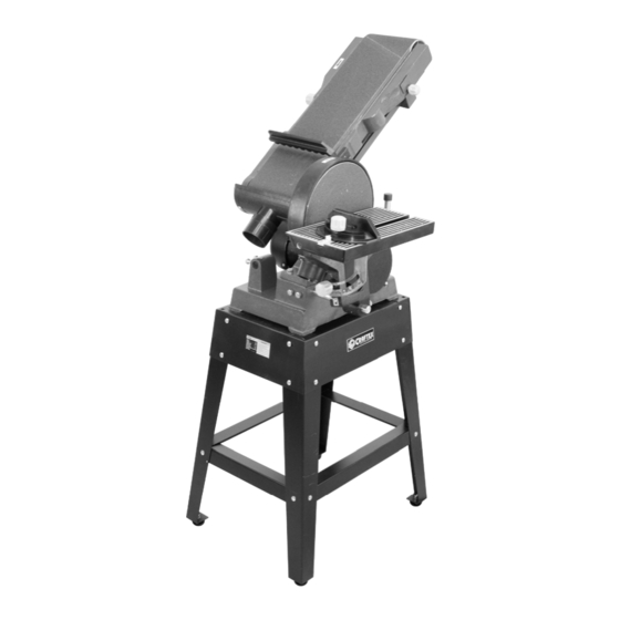
- Page 1 CT180 6” x 48" BELT AND 9" DISC SANDER User Manual...
-
Page 2: Table Of Contents
TABLE OF CONTENTS General Safety Instructions ................3 Specific Safety Instructions................4 CT180 Features....................5 Physical Features ..................6 Set Up ......................7 Unpacking ....................7 Proper Grounding ..................8 Stand Assembly....................9 Mounting the Machine on to the Stand ............10 Installing the Dust Ports................10 Installing the Table ..................11 Installing the Backstop..................11... -
Page 3: General Safety Instructions
GENERAL SAFETY INSTRUCTIONS Extreme caution should be used when operating all power tools. Know your power tool, be familiar with its operation, read through the owner’s manual and practice safe usage procedures at all times. ALWAYS read and understand the router bits, shaper heads, blades, user manual before operating the knives or making other adjustments or... -
Page 4: Specific Safety Instructions
CT180 – 6” x 9” BELT & DISC SANDER SPECIFIC SAFETY INSTRUCTIONS MAKE SURE the sander is connected ALWAYS wear a dust mask and safety to the matched and specific power glasses while operating the sander. The source instructed in the manual. -
Page 5: Ct180 Features
MODEL CT180 – 6” x 9” BELT & DISC SANDER As part of the growing line of Craftex woodworking equipment, we are proud to offer the CT180 a 6” x 9” Belt and Disc Sander. By following the instructions and procedures laid out in this user manual, you will receive years of excellent service and satisfaction. -
Page 6: Physical Features
CT180 – 6” x 9” BELT & DISC SANDER PHYSICAL FEATURES 6” x 48” Quick Release Sanding Belt Tension Lever Belt Guard Cover Lock Knob Backstop 9” Sanding Disc 2.5” Dust Port Table Stop Work Table 1-HP Motor Miter Gauge 2.5"... -
Page 7: Setup
WARNING! LIST OF CONTENTS CT180 is a heavy machine, do not over- exert yourself. For safe moving method A. Sander ..........1 use a mechanical device or get the help B. Stand Lower Brackets (Long) ..2 of an assistant. -
Page 8: Proper Grounding
It is strongly recommended not to use Grounding provides path least extension cords with your CT180. Always resistance for electric current to reduce the try to position your machine close to the risk of electric shock. power source so that you do not need to use extension cords. -
Page 9: Stand Assembly
STAND ASSEMBLY The CT180 comes with an open stand that needs to be assembled before installing the sander onto it. WARNING! While assembling the stand, place a piece of carton or cloth on the floor to prevent the stand legs and brackets from being scratched. -
Page 10: Mounting The Machine On To The Stand
Place the stand upside down on the floor INSTALLING THE DUST and attach the four rubber feet to the each PORTS leg securing it with the nuts and washers provided. See figure-5. Install the dust ports to the back of the sanding belt frame and to the bottom of the sanding disc cover using the screws and washers provided. -
Page 11: Installing The Table
INSTALLING THE TABLE INSTALLING THE BACKSTOP The table is most commonly installed to be used with the sanding disc but it can also When the sanding belt is set for horizontal be installed to be used with the sanding belt sanding, the backstop should be used to when the sanding belt is in vertical position. -
Page 12: Belt Tension Handle
Belt tracking means where the belt rides on sanding platen. See figure-12. the rollers. The belt should always be centered on both the rollers. Your CT180 sander is shipped with the belt tracking mechanism properly adjusted. -
Page 13: Dust Collection
DUST COLLECTION or jam against the sander during the test run. CT180 features two 2-1/2” dust ports to connect to a dust collector. Remove all the tools and objects used for the machine set up and installation before When connecting to a dust collector, use a the test run. -
Page 14: Work-Piece Inspection
WORK-PIECE INSPECTION HORIZONTAL/VERTICAL SANDING CT180 is designed to sand wood only. Do not use this machine to sand metals, glass The belt sander can be positioned vertically or stone etc. or horizontally and it can also be positioned at any angle in between, depending on your Before sanding, make sure to inspect the sanding needs. -
Page 15: Adjusting The Miter Gauge
When using the belt sander in horizontal ADJUSTING THE MITER position, make sure to install the backstop GAUGE to the sanding frame, so that the work-piece does not fly out. See figure-19. The miter gauge is used to hold and support the work-piece at a desired angle during sanding operation. -
Page 16: Sanding Tips
THE SANDING DISC experience poor unsatisfactory results, or the sanding disc The CT180 comes with a 9” PSA (pressure may loose contact with the plate during sensitive adhesive backed disc). operation if there is dust or debris on the plate surface. - Page 17 THE SANDING BELT arrow on the back of the sanding belt is positing towards the sanding disc. The CT180 comes with a 6” x 48” sanding belt. Once the belt is installed onto the rollers, turn the belt tension lever back to the right TO INSTALL/REMOVE THE SANDING to tension the belt.
-
Page 18: Maintenance
MAINTENANCE V-BELT TENSION & REPLACEMENT During the lifetime of your machine, you will need to practice some regular maintenance The V-belt is pre-installed and tension at to keep your sander in peak operating the factory. It stretches with use and should condition. - Page 19 Figure-25 Motor mounting lock nuts Figure-26 Correct belt tension At this point the V-belt should be loose enough to slip it off the pulleys. If the deflection is not approximately 1/4" when you push with moderate pressure, Replace the V-belt with a new one and loosen the motor mounting nuts and re- install it on the pulleys.
-
Page 20: Troubleshooting
TROUBLESHOOTING... -
Page 22: Parts List
CT180 PARTS LIST DESCRIPTION SIZE Spring DESCRIPTION SIZE Base Strain Relief Feet Carriage Bolt M8×12 Support rod Sleeve Layer board Flat washer Upper Long Braces Bearing 80102 Bolt M8×30 Screw M4×12 Washer Upper Short Braces Main Shaft B5×28 Screw M4×8... - Page 23 DESCRIPTION SIZE Abrasive Disc 9" Screw M6×16 Washer B Angle support Table Support Bracket Pointer Plug Bolt Knob End cap Knob Bolt Cover plate Screw M4×16 Bolt M8×16 Lower Short Bracket Lower Long Bracket Bolt Round pin Miter Gauge Body φ15 Washer Knob...
-
Page 24: Warranty
This warranty shall not apply to consumable products such as blades, bits, belts, cutters, chisels, punches etceteras. Craftex shall in no event be liable for injuries, accidental or otherwise, death to persons or damage to property or for incidental contingent, special or consequential damages arising from the use of our products.
Need help?
Do you have a question about the CT180 and is the answer not in the manual?
Questions and answers