Table of Contents
Advertisement
Advertisement
Table of Contents

Related Manuals for Vinten pro-touch Pro-10 System


Summary of Contents for Vinten pro-touch Pro-10 System
- Page 1 Contents Next Previous Page View pro-touch Vinten Camera Control Solutions...
- Page 2 All rights reserved throughout the world. No part of this document may be stored in a retrieval system, transmitted, copied or reproduced in any way including, but not limited to, photocopy, photograph, magnetic or other record without the prior agreement and permission in writing of Vinten Broadcast Limited. Vinten is a registered trademark of Vinten Broadcast Limited.
- Page 3 Particular attention must be paid to cleaning, especially after use in adverse conditions. To order spare parts or to obtain further information, application should be made to Vinten Broadcast Limited or to your local distributor, or visit our website at www.vinten.com.
-
Page 4: Notes To Readers
Contents First Previous Next Previous Page Page Page View Notes to readers This is the on-line version of ‘protouch Pro-10 System Maintenance Manual’ (3809-9). Readers should be aware that the pagination differs between on-line and printed versions. Navigation Clicking the mouse on any blue text will move you around the document. -
Page 5: Safety - Read This First
Contents First Previous Next Previous Page Page Page View Safety - Read This First! Warning symbols in this maintenance manual Where there is a risk of personal injury, injury to others, or damage to the system or associated equipment, comments appear, highlighted by the word WARNING! and supported by the warning triangle symbol. - Page 6 First Previous Next Previous Page Page Page View Contents Page Foreword ................3 Notes to readers .
- Page 7 Contents First Previous Next Previous Page Page Page View Illustrations Page Fig 1.1 Pro-10 pan and tilt head ............12 Fig 1.2 Pozi-Loc tripod and floor spreader .
- Page 8 Contents First Previous Next Previous Page Page Page View Abbreviations The following abbreviations are sued in this publication: alternating current pound (weight) Amps Lubricated Friction across flats left hand as required MISO metric thread ASME American Society of Mech Engineers metre assy assembly...
-
Page 9: Technical Specification
Contents First Previous Next Previous Page Page Page View Technical Specification Pro-10 pan and tilt head Weight Head 2.32 kg (5.1 lb) Pan bar 0.28 kg (0.6 lb) Bowl clamp 0.1 kg (0.2 lb) Height to mounting face 13.8 cm (5.4 in.) Length 16 cm (6.3 in.) Width... -
Page 10: Design Improvements
Contents First Previous Next Previous Page Page Page View Design Improvements SERIAL No. DETAILS INFORMATION Improvements to tripod bottom clamp adjuster Tripod 3810-03515... -
Page 11: Introduction And Description
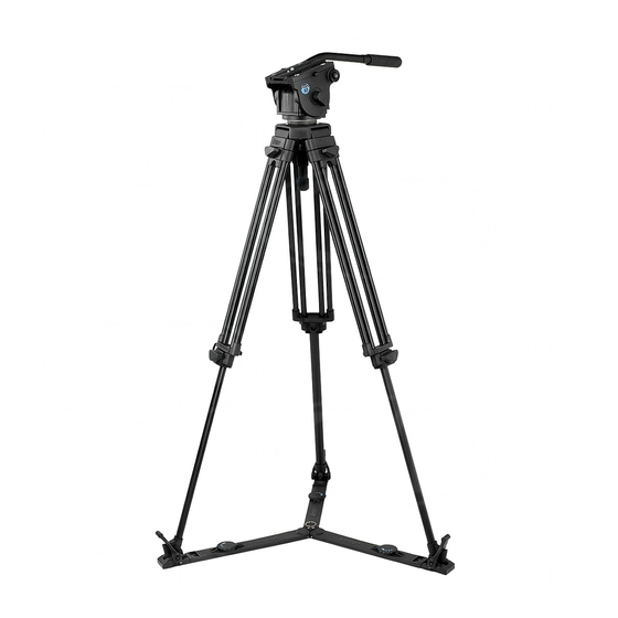
Floor spreader ..............11 Introduction The protouch Pro-10 system from Vinten comprises a Pro-10 pan and tilt head, a Pozi-Loc two-stage tripod, an adjustable floor spreader and a soft case. - Page 12 Contents First Previous Next Previous Page Page Page View (18) (17) (16) (15) (14) (13) (12) (11) (10) Fig 1.1 Pro-10 pan and tilt head...
-
Page 13: Camera Mounting
Contents First Previous Next Previous Page Page Page View Camera mounting The camera is attached to the head by means of a slide plate (14), which is provided with a spring- loaded locating pin and 1/4 in. (18) and 3/8 in. screws. -
Page 14: Fig 1.2 Pozi-Loc Tripod And Floor Spreader
Contents First Previous Next Previous Page Page Page View (26) (19) (25) (20) (24) (22) (21) (23) Fig 1.2 Pozi-Loc tripod and floor spreader... -
Page 15: Operation
Contents First Previous Next Previous Page Page Page View Section 2 Operation Contents Para General................1 Assembly Tripod and spreader . -
Page 16: Pan And Tilt Head
Contents First Previous Next Previous Page Page Page View Pan and tilt head The Pro-10 pan and tilt head is supplied with a removable 75 mm ball mount. Adaptors are available which enable the head to be installed on tripods or pedestals fitted with other mountings. These are listed under ‘Optional Accessories’. -
Page 17: Pan And Tilt Drag
Contents First Previous Next Previous Page Page Page View in. mm Payload Fig 2.1 Balance graph Pan and tilt drag Both the pan and tilt mechanisms incorporate a fluid drag system to ensure smooth movement of the camera about these axes. The tilt drag adjustment knob is on the right -hand side of the head, the pan drag knob (17) -
Page 18: Tools And Materials
General lubrication Shell Darina R2 grease (yellow) General lubrication PTFE dry lubricant (Aerosol) Pan drag ball bearing Optalus A0 140 Pan and tilt friction White bearing grease (Vinten Part No. Z150-085) Tripod clamps Loctite 221 (Vinten Part No. Z002-026) Screw locking... -
Page 19: Routine Maintenance
Contents First Previous Next Previous Page Page Page View Section 4 Servicing Contents Para General................1 Cleaning . -
Page 20: Fig 4.1 Battery Replacement
Contents First Previous Next Previous Page Page Page View Check for ageing and cracking of the rubber foot securing straps on the spreader and renew if necessary. No further routine maintenance is required. Battery replacement The battery illuminates the level bubble (10) when the switch (13) is pressed. The level bubble remains lit for approximately 15 seconds. -
Page 21: Pan Brake Knob Adjustment
Contents First Previous Next Previous Page Page Page View Adjustments Pan brake knob adjustment Because its movement is restricted, the pan brake knob (11) may require adjustment after prolonged use. To adjust the pan brake knob (Fig 4.2): 10.1 Remove the securing screw (11.1) and pull the knob (11) -
Page 22: Camera Slide Plate Knob Adjustment
Contents First Previous Next Previous Page Page Page View Camera slide plate knob adjustment To prevent interference with the payload, the camera slide plate knob should be at or below the horizontal when applied. To adjust the camera slide plate knob (Fig 4.2): 12.1 Remove the securing screw... - Page 23 Contents First Previous Next Previous Page Page Page View (20.2) (20) (20.1) Fig 4.3 ‘Pozi-Loc’ tripod leg - top clamp adjustment Bottom clamp The design of the bottom clamp changed at tripod Serial No. 03515. Identify version as follows (Fig 4.4): 15.1 Turn the clamp knob (20)
- Page 24 Contents First Previous Next Previous Page Page Page View (20.3) IDENTIFICATION 90° GROOVE (20) POSITION 1 (20.4) (20.5) (20.6) (20.3) (20.7) (20.3) (20.8) (20.9) (20) (20) (20.4) (20.8) (20.5) (20.4) (20.6) (20.5) (20.6) Earlier clamp - two grubscrews Later clamp - One grubscrew Fig 4.4 ‘Pozi-Loc’...
- Page 25 Contents First Previous Next Previous Page Page Page View 16.5 Back off the adjusting grubscrew (20.7) by a quarter-turn (90°). 16.6 Turn the clamp knob (20) to Position 1 (fully ‘on’). 16.7 Replace and tighten the locking grubscrew (20.8), using Loctite 221 and allow 15 minutes for the Loctite to set.
- Page 26 Contents First Previous Next Previous Page Page Page View Section 5 Repair Contents Para Repair ................26 Repair Disassembly Ball clamp assembly .
-
Page 27: Pro-10 Pan And Tilt Head
Contents First Previous Next Previous Page Page Page View Pro-10 pan and tilt head Disassembly Ball clamp assembly Remove the ball clamp assembly as follows (Fig 6.4): Unscrew and remove the bowl knob (6). Remove three grub screws (5.2). Unscrew the ball clamp assembly (5.1) from the pan base. Platform Remove the platform as follows (Fig... - Page 28 Contents First Previous Next Previous Page Page Page View Left flange assembly Remove the left flange assembly as follows (Fig 6.2): Remove two screws (10.3) securing the left flange assembly (11) to the centre housing (10.2) and pull off the left flange assembly. If required, screw out the tilt brake knob (12.2).
- Page 29 Contents First Previous Next Previous Page Page Page View 11.4 Remove the nut (9.1), the bearing (9.2) and the washer (9.3) from the shaft of the pan base (Fig 6.4, item 3.2). 11.5 Referring to 6.4, pull the pan base (3.2) and associated components (pan bearing (2) and drag disc (3.1)) out of the centre housing (1.2).
- Page 30 Contents First Previous Next Previous Page Page Page View 13.4 Install two springs (7.2) and two drag adjustment shoes (7.1) in the slots in the centre housing (1.2). 13.5 Position the adjustable drag disc (3.1) over the pan drag adjuster stud (3.2) with the legs of the disc through the slots in the centre housing (1.2).
- Page 31 Contents First Previous Next Previous Page Page Page View 16.2 Secure with two screws (10.3). Left flange assembly Install the left flange assembly as follows (Fig 6.2): 17.1 If removed, install the bearing (12.1) on the shaft of the tilt brake knob (12.2) and screw the tilt brake knob into the left flange assembly (11).
-
Page 32: Pozi-Loc Tripod
Contents First Previous Next Previous Page Page Page View Install the ball clamp assembly as follows (Fig 6.4): 21.1 Screw the stud of the ball clamp assembly (5.1) into the pan base. 21.2 Install three grub screws (5.2) and tighten to lock the ball clamp assembly. 21.3 Install the bowl clamp (6). -
Page 33: Replacing The Components Of The Top Clamp Assembly
Contents First Previous Next Previous Page Page Page View Replacing the components of the top clamp assembly Dismantling Dismantle the top clamp as follows (Fig 6.6): 26.1 Turn the clamp (28) counter-clockwise to the ‘OFF’ position. 26.2 Remove screw (14). Using a suitable peg spanner, unscrew and remove the threaded insert (13). 26.3 Remove the clamp assembly (12) from the top clamp moulding. - Page 34 Contents First Previous Next Previous Page Page Page View 29.2 Using a suitable instrument, such as a flat-bladed screwdriver, carefully remove the knob cap (26). 29.3 Remove the screw (25), washer (24) and clamp knob (23). 29.4 Remove the grubscrew (16). Remove the oval leg as follows (Fig 6.6):...
- Page 35 Contents First Previous Next Previous Page Page Page View 36.2 Using a suitable instrument, such as a flat-bladed screwdriver, carefully remove the knob cap (26). 36.3 Remove the screw (25), washer (24) and clamp knob (23). 36.4 Remove the locking and adjusting grubscrews (30). Remove the oval leg as follows (Fig 6.6):...
-
Page 36: Illustrated Parts List
Fig 6.7 Floor Spreader (3818-3) ............52 Introduction This parts list is issued for the protouch Pro-10 system, manufactured for Vinten Broadcast Limited, Western Way, Bury St. Edmunds, Suffolk, IP33 3TB, England. -
Page 37: Main Assembly Part Numbers
Contents First Previous Next Previous Page Page Page View Main assembly part numbers Ensure that the correct serial and part numbers are quoted when ordering main assemblies. Assembly Part No. Pro-10 pan and tilt head, comprising: 3809-3 Pro-10 pan and tilt head - main unit assembly 3809-11 Pan bar assembly 3219-104... - Page 38 Contents First Previous Next Previous Page Page Page View Fig 6.1 Pro-10 System...
- Page 39 Contents First Previous Next Previous Page Page Page View Fig 6.1 Pro-10 System Item Part Nomenclature 3809-3 Pro-10 pan and tilt head (Fig 6.2) 3819-3 Pozi-Loc two-stage tripod (Fig 6.5) 3818-3 Floor spreader (Fig 6.7)
- Page 40 Contents First Previous Next Previous Page Page Page View 14.1 14.2 Fig 6.3 10.1 10.2 12.1 10.3 12.2 10.4 10.3 PRO10IP03 Fig 6.4 Fig 6.2 Pro-10 Pan and Tilt Head - Main Castings and Platform...
- Page 41 Contents First Previous Next Previous Page Page Page View Fig 6.2 Pro-10 Pan and Tilt Head - Main Castings and Platform Item Part Nomenclature 3809-900SP Camera plate for Pro-10 Screw, camera mounting, 1/4 in. BSW Screw, camera mounting, 3/8 in. BSW Slide plate Plug, camera screw blanking R503-216...
- Page 42 Contents First Previous Next Previous Page Page Page View Fig 6.2 Pro-10 Pan and Tilt Head - Main Castings and Platform (Cont) Item Part Nomenclature Nut, M10, nyloc, thin Bearing, ball, thrust, 10 mm ID x 17 mm OD x 4.7 mm long Washer, stainless steel, 11 mm ID x 30 mm OD x 2.5 mm thick R516-206 Assembly, base casting...
- Page 43 Contents First Previous Next Previous Page Page Page View Fig 6.2 6.1.1 6.1.2 6.1.3 6.1.4 6.1.5 Fig 6.4 PRO10IP04 Fig 6.3 Pro-10 Pan and Tilt Head - RH Side Plate, Tilt Drag and Pan Bar...
- Page 44 Contents First Previous Next Previous Page Page Page View Fig 6.3 Pro-10 Pan and Tilt Head - RH Side Plate, Tilt Drag and Pan Bar Item Part Nomenclature R516-08 Assembly, plate brake R503-220 Assembly, friction knob Boot, tilt drag knob Nut, M6, standard (hex), full Knob, tilt drag Bearing, ball, thrust, 6 mm ID x 14 mm OD x 4.7 mm long...
- Page 45 Contents First Previous Next Previous Page Page Page View Fig 6.2 Fig 6.3 Fig 6.2 4.1.1 4.1.2 PRO6IP08 Fig 6.4 Pro-10 Pan and Tilt Head - Pan Drag and Ball Base...
- Page 46 Contents First Previous Next Previous Page Page Page View Fig 6.4 Pro-10 Pan and Tilt Head - Pan Drag and Ball Base Item Part Nomenclature R516-206 Assembly, base casting Assembly, bubble Assembly, centre housing spares Screw, low profile, cap head, socket, M6 x 16 mm long Sleeve, pan bearing R3-2185 Bearing f/516 head...
- Page 47 Contents First Previous Next Previous Page Page Page View Fig 6.5 Pozi-Loc Two-Stage Tripod (3819-3)
- Page 48 Contents First Previous Next Previous Page Page Page View Fig 6.5 Pozi-Loc Two-Stage Tripod (3819-3) Item Part Nomenclature 3774-15 Bowl assembly (75mm) 3498-322 Hook 3819-11 Two-stage leg assembly 3310-12 Strap assembly...
- Page 49 Contents First Previous Next Previous Page Page Page View Earlier tripods - two M5 grubscrews 3770_3_IP Fig 6.6 Leg Assembly (3819-11)
- Page 50 Contents First Previous Next Previous Page Page Page View Fig 6.6 Leg Assembly (3819-11) Item Part Item 3774-15 Bowl assembly (75mm) 3498-321 Leg Pivot Clamp 3498-338 Spherical Washer M007-506 Screw, button head, socket, M6 x 20 mm long J550-112 Cap, tube, dome type, to fit over 3.2 mm diameter 3498-322 Hook 3498-226...
- Page 51 Contents First Previous Next Previous Page Page Page View Fig 6.6 Leg Assembly (3819-11) (Cont) Item Part Item NOTE: The design of the bottom clamp has been modified At Serial No. 03515, the shaft was fitted with a locking thread insert and the 2 x M5 grubscrews, were changed to 1 x M5 x 10 mm Earlier tripods - two M5 grubscrews 3770-213...
- Page 52 Contents First Previous Next Previous Page Page Page View Fig 6.7 Floor Spreader (3818-3)
- Page 53 Contents First Previous Previous Page Page View Fig 6.7 Floor Spreader (3818-3) Item Part Nomenclature 3313-219 Split ring 3363-201 Centre moulding 3313-211 Hinge pin M701-054 'E'-Clip, crescent ring (“e”-clip variation), 4 mm shaft dia. x 0.40 mm thick 3363-202 Leg moulding inner (female) 3313-214 Friction pad 3313-213...
Need help?
Do you have a question about the pro-touch Pro-10 System and is the answer not in the manual?
Questions and answers