Sign In
Upload
Download
Table of Contents
Contents
Add to my manuals
Delete from my manuals
Share
URL of this page:
HTML Link:
Bookmark this page
Add
Manual will be automatically added to "My Manuals"
Print this page
×
Bookmark added
×
Added to my manuals
Manuals
Brands
Vinten Manuals
Camera Accessories
FH-145
User manual
Vinten FH-145 User Manual
Pan and tilt head
Hide thumbs
1
2
Table Of Contents
3
4
5
6
7
8
9
10
11
12
13
14
15
16
17
18
19
20
21
22
23
24
25
26
27
28
page
of
28
Go
/
28
Contents
Table of Contents
Troubleshooting
Bookmarks
Table of Contents
Pan and Tilt Head
Table of Contents
Safety and Warnings
Components and Connections
Installation
Mounting Supports and Adaptors
Cable Management Brackets
HD Tripod Mounting Options
Locking/Unlocking the Camera Cradle
Mounting the Camera
Balancing the Head
Electrical Connections
Cable Management
Powering up
Operation
Maintenance
Troubleshooting
General Notices
Advertisement
Quick Links
1
Pan and Tilt Head
2
Mounting Supports and Adaptors
3
Locking/Unlocking the Camera Cradle
4
Electrical Connections
5
Powering up
6
Operation
7
Troubleshooting
Download this manual
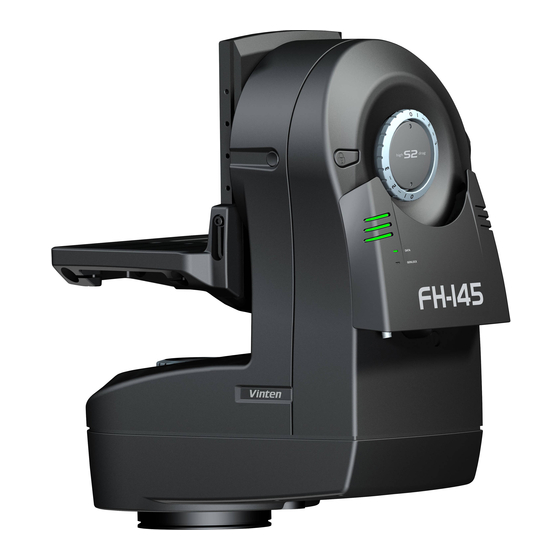
FH-145
FHR-145
Pan and Tilt Head
Part Nos. V4101-0001
V4102-0001
www.vinten.com
Table of
Contents
Previous
Page
Next
Page
1
2
3
4
5
Advertisement
Table of Contents
Need help?
Do you have a question about the FH-145 and is the answer not in the manual?
Ask a question
Questions and answers
Related Manuals for Vinten FH-145
Camera Accessories Vinten FHR-145 User Manual
Pan and tilt head (28 pages)
Camera Accessories Vinten flowtech 75 User Manual
(20 pages)
Camera Accessories Vinten V4160-0001 User Manual
(28 pages)
Camera Accessories Vinten V4150-0004 User Manual
(28 pages)
Camera Accessories Vinten FH155 Manual User Manual
Robotic and manual pan and tilt heads (28 pages)
Camera Accessories Vinten Fulmar Pedestal Maintenance Manual
(85 pages)
Camera Accessories Vinten RADAMEC Fusion FH-100 Operator's Manual
Robotic and manual pan & tilt head (38 pages)
Camera Accessories Vinten FHR-35 User Manual
Robotic pan and tilt head (32 pages)
Camera Accessories Vinten FE-55 User Manual
Robotic elevation unit (40 pages)
Camera Accessories Vinten FE-165 Light User Manual
Robotic elevation unit (40 pages)
Camera Accessories Vinten Quattro-OBL Operator's Manual
Pedestal (25 pages)
Camera Accessories Vinten OSPREY lite User Manual
(32 pages)
Camera Accessories Vinten Vision 10LF Maintenance Manual
Pan and tilt head (53 pages)
Camera Accessories Vinten Vision 8 Maintenance Manual
Pan and tilt head (52 pages)
Camera Accessories Vinten Vision 100 Operator's Manual
Pan and tilt head (19 pages)
Camera Accessories Vinten Protouch Pro-6HDV System Maintenance Manual And Parts List
Original instructions (67 pages)
This manual is also suitable for:
Fhr-145
Table of Contents
Print
Rename the bookmark
Delete bookmark?
Delete from my manuals?
Login
Sign In
OR
Sign in with Facebook
Sign in with Google
Upload manual
Upload from disk
Upload from URL


Need help?
Do you have a question about the FH-145 and is the answer not in the manual?
Questions and answers