Advertisement
Quick Links
Advertisement

Related Manuals for HMS TYTAN 15


Summary of Contents for HMS TYTAN 15
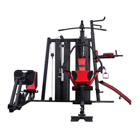
- Page 1 TYTAN 15 HOME GYM hms-fitness.com MANUAL INSTRUCTION...
-
Page 2: Maintenance
TECHNICAL DATA: Net weight – 370 kg Dimensions when unfolded – 246 x 332 x 218 cm Maximum permissible loading of the product – 140 kg hms-fitness.com... - Page 3 LIST OF PARTS hms-fitness.com...
- Page 4 hms-fitness.com...
- Page 5 2. Tighten all bolts manually at initial stage. Use relevant tool to tighten the screws only when a given element has been fully assembled. 3. Some elements may be pre-assembled at the factory. 4. 2 persons are required to assemble the machine. hms-fitness.com...
- Page 6 2. Insert the tube (22) into the opening in the side section of the platform (21) and bottom part of the fra- me (3). 3. Level the openings in both parts (22 and 3) and drive in the pin (35). 4. Put end caps (67) on both ends of the tube (21) and end caps (70) of the frame (3). hms-fitness.com...
- Page 7 4. Fix the buffer (89) to the leg press frame (121). 5. Connect the frame (121) with other frames (123, 2, 1, 3) using screws (154), washers (114) and nuts (118). Install the plate at the same time. 6. Put the end cap (69) on the frame (121). hms-fitness.com...
- Page 8 1. Put end cap (176) on the frame (158) and the buffer (70) on the frame (4). 2. Fix the frame (130) to the frame (123); frame (158) to the frame (2); frame (4) to the frame (3) using screws (103), washers (114) and nuts (118). hms-fitness.com...
- Page 9 3. Inset flange (53) on the selector (52) and drive the pin (55) through the flange (53) and selector (52), carefully placing the weight (50) on the stack. Lock it with the safety pin (36) and insert a washer (54). hms-fitness.com...
- Page 10 10. Connect the frame (5) with frame (122) using screws, washers and nuts (96, 114, 118), leaving slight cle- arance on screws. Connect the frame (5) with frame (157) using screws, washers and nuts (101, 114, 118) and tighten all screws. hms-fitness.com...
- Page 11 4. Fasten top cover supports (166) to the frame (5) with screws (94), leaving slight clearance until the mo- unting of covers (39) in step 29. ON COMPLETION OF THESE ACTIVITIES, TIGHTEN ALL SCREWS FROM STEP 6 AND 7 (except for subpoint 4). hms-fitness.com...
- Page 12 118), leaving slight clearance on screws and fixing the arm (4) with screws, washers and nuts (100, 114, 118). Next, tighten all screws all the way. STEP 9 1. 1. Place arms (9) on the frame (8), lubricating the tucked-in part; lock both arms (9) with retaining rings (86). hms-fitness.com...
- Page 13 2. Put foam rollers (165) on the handles of press arm (after soaking them in warm water). Install part (66 and 69). 3. Put arm (13) on the frame (24). Level the openings and insert the roller (31). Fasten with screws (95) and washers (117). 4. Insert the end cap (82). hms-fitness.com...
- Page 14 1. Fix the backrest (42) to the frame (25) using screws, washers and nuts (96, 114, 73). 2. Install everything on the arm (4) using screws, washers and nuts (105, 116, 119). Put on end caps (74). Adjust the screws so that the arm can easily be adjusted. 3. Fix end cap (81). hms-fitness.com...
- Page 15 2. Drive the support (18) along with the preacher curl pad into the frame (16) and secure it with safety pin (88). 3. Insert the roller (23) into the frame (16) and arm (15); put on end caps (66). 4. Put on foam rollers (63). hms-fitness.com...
- Page 16 (159) and right (160) bar. 2. Fasten both bars to the frame (157) using screws, washers and nuts (100, 114, 118). 3. Fix bars (164) and grips (77) to both bars using screws and washers (96, 115). Carefully tighten all screws. hms-fitness.com...
- Page 17 4. Drive the roller (169) into the frame (167). Put on end caps (66) and place foam rollers (175). 5. Drive the roller (169) into the frame (158) to the desired height. Put on end caps (66) and foam rollers (175). hms-fitness.com...
- Page 18 2. Level the openings of the bearing (144), frame (131) and frame (127). 3. Drive the roller (138) into the openings of the bearing (144), frame (131) and frame (127), and lock with screw (151). 4. Tighten the Allen screws on the bearing rings (144). hms-fitness.com...
- Page 19 1. Fix the oil absorber (136) to the arm (127) and frame (131) using two screws M6*25 (148) and nuts M6 (156). STEP 22 1. Fasten the screw (149) into openings in parts (127 and 131), after levelling them. hms-fitness.com...
- Page 20 3. Level the openings in the arm (127) and frame (133). Insert the roller (137) and put on bushings (139), fixing them with Allen screws and washers (150, 147). 4. Fix the platform (128) on the arm (133) and fasten with screws and washers (96, 114). hms-fitness.com...
- Page 21 Next, tighten the screws (155). STEP 26 1. Place the grip (77) on the left (124) and right (125) handpiece. 2. Fix the grips (124, 125) to the frame (121) – use screws (103), washers (115) and nuts (118). hms-fitness.com...
- Page 22 STEP 27 1. Fasten the seat (134) to parts (121, 124 and 125) – use screws (153, 96) and washers (114). 2. Fasten the backrest (135) to the frame (121) using screws (153) and washers (114). hms-fitness.com...
- Page 23 If the cable is very loose, adjust the line pulley to bottom position (no. 28). Unscrew the nut and threaded screw in part (14) to adjust the cable tension. Loosen the screw of the nut and thread in the top plate section to achieve correct cable tensioning. hms-fitness.com...
- Page 24 BACK TENSIONING CABLE Loosen the screw of the nut and thread in the top plate section to achieve correct cable tensioning. hms-fitness.com...
- Page 25 LOW PULLEY CABLE hms-fitness.com...
- Page 26 SIDE PULLEY CABLE (ARMS) hms-fitness.com...
- Page 27 Fasten parts (11 and 9) with screws (108). Pull the cable in arms through arms (9) using control wire (steel wire). hms-fitness.com...
- Page 28 FRONT TENSIONING CABLE Drive the cable into the opening and tighten with Allen screws (107). hms-fitness.com...
- Page 29 Loosen the screw of the nut and thread in the top plate section to achieve correct cable tensioning. hms-fitness.com...
- Page 30 STEP 29 1. Fasten the covers (39) with openings for HMS logo from the side of the leg press frame using screws and washers (93, 113). 2. Fasten the covers (39) on supports (17 and 166) with screws and washers (92, 110).
- Page 31 Św. Elżbiety St. 6, 41-905 Bytom, POLAND abisal@abisal.pl www.abisal.pl www.hms-fitness.com Labelling the product with a symbol of a crossed waste container informs us that the worn-out electrical and electronic equipment cannot be put into the same container as other waste. According to the WEEE Directive on the management of electrical and electronic waste, separate recycling methods shall be used for this type of equipment.
-
Page 32: Guarantee Card
The guarantee for sold goods is not exclusive, does not limit or suspend entitlements of the buyer resulting from the non-com- pliance of the product with the agreement. THE EQUIPMENT IS NOT INTENDED FOR REHABILITATION AND THERAPY NOTES ON THE COURSE OF REPAIRS hms-fitness.com...
Need help?
Do you have a question about the TYTAN 15 and is the answer not in the manual?
Questions and answers