Sign In
Upload
Manuals
Brands
IEI Technology Manuals
Desktop
ECK-1000-690S1
IEI Technology ECK-1000-690S1 Manuals
Manuals and User Guides for IEI Technology ECK-1000-690S1. We have
1
IEI Technology ECK-1000-690S1 manual available for free PDF download: User Manual
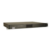
IEI Technology ECK-1000-690S1 User Manual (102 pages)
1U Embedded System for Large Digital Displays Includes Audio, DVI and VGA, PCI Slots, Dual Gigabit Ethernet and USB
Brand:
IEI Technology
| Category:
Desktop
| Size: 3 MB
Table of Contents
Table of Contents
7
1 Introduction
13
Figure 1-1: ECK-1000
14
Introduction
14
ECK-1000 Models
14
Table 1-1: Technical Specifications
14
ECK-1000 Benefits
15
ECK-1000 Features
15
Eck-1000 Overview
15
ECK-1000 Overview Photo
15
ECK-1000 Peripheral Connectors and Jumpers
16
Figure 1-3: ECK-1000 Overview [Rear View]
16
Figure 1-2: ECK-1000 Overview [Front View]
16
Technical Specifications
17
Table 1-2: Technical Specifications
18
2 Mechanical Description
19
Mechanical Overview
20
Physical Dimensions
20
ECK-1000 Dimensions
20
Figure 2-1: ECK-1000 Dimensions (MM)
21
External Overview
22
Figure 2-3: ECK-1000 Front Panel
22
Figure 2-2: KINO SBC Dimensions (MM)
22
Figure 2-5: ECK-1000 Cooling Vents
24
Figure 2-6: ECK-1000 Internal Overview
25
Internal Overview
25
Component Specifications
26
Cooling Fans
26
Figure 2-7: Cooling Fan Dimensions (MM)
26
Motherboard
26
ACE-4518AP PSU Specifications
27
Table 2-1: Cooling Fan Specifications
27
Table 2-2: ACE-4525AP PSU Specifications
29
Front Panel
22
Figure 2-4: ECK-1000 Rear Panel
23
Cooling Vents
24
Motherboard Dimensions
22
Front Panel Buttons and Indicators
23
Rear Panel
23
Rear Panel Connectors
23
3 Unpacking
31
Unpacking
32
Unpacking Precautions
32
Unpacking Checklist
32
Package Contents
32
Table 3-1: Package List Contents
33
4 Installation
35
Anti-Static Precautions
36
Installation Procedure
36
Unpacking
37
Figure 4-1: Top Cover Retention Screws
38
Figure 4-2: Connector Fastening Screws
39
Figure 4-3: Internal Cables
39
Figure 4-4: Motherboard Fastening Screws
40
Figure 4-5: Make Sure the CPU Socket Retention Screw Is Unlocked
41
Cooling Kit Installation
42
Motherboard Removal
38
Top Cover Removal
38
Figure 4-6: Lock the CPU Socket Retention Screw
42
Figure 4-7: Cooling Kit
42
Figure 4-10: Installing a DIMM
45
Figure 4-11: SO-DIMM Installation
46
SO-DIMM Installation (ECK-1000-690S1)
46
Drive Installation
47
Figure 4-12: Hard Drive Bracket Retention Screws
47
Hard Drive Installation
47
CD Drive Installation
48
Figure 4-13: Hard Drive Screws
48
Figure 4-14: CD Drive Bracket Retention Screws
48
ATA Flat Cable Connection
49
Figure 4-15: CD Drive Screws
49
Figure 4-16: IDE Cable Connection
50
SATA Drive Connection
50
Figure 4-17: SATA Drive Cable Connection
51
Figure 4-18: SATA Power Drive Connection
52
PCI Card Installation
52
Figure 4-19: Cooling Fan Retention Screws on the Fan Bracket
53
Figure 4-20: Cooling Fan Retention Screws on the Fan Bracket
53
Figure 4-21: Jumper Locations
54
Jumper Settings
54
Table 4-1: Jumpers
54
Clear CMOS Jumper
55
Table 4-2: Clear CMOS Jumper Settings
55
COM Port Function Select Jumper
56
Figure 4-22: Clear CMOS Jumper
56
Table 4-3: Function Select Jumper Settings
56
Cover Reinstallation
57
Internal Peripheral Device Connections
57
Table 4-4: IEI Provided Cables
57
VESA Mounting Plate Installation
57
External Peripheral Interface Connection
58
Audio Connection
59
LAN Connection (Single Connector)
59
PS/2 Keyboard and Mouse Connection
60
Serial Device Connection
61
USB Connection (Dual Connector)
62
DVI Display Device Connection
63
VGA Monitor Connection
64
Monitor Installation
65
Power on
67
Figure 4-9: Connect the Cooling Fan Cable
43
Memory Installation
44
DIMM Installation (ECK-1000-9453)
44
Motherboard Installation
44
CPU Installation
40
5 Bios Settings and Driver Installation
69
6 Troubleshooting and Maintenance
71
Eck-1000 System Maintenance Overview
72
System Troubleshooting
72
The System Doesn't Turn on
72
The System Doesn't Boot up
73
More Troubleshooting
73
Component Replacement Procedure
74
DIMM Module Replacement
74
Motherboard Replacement
74
Power Supply Replacement
74
Power Supply Removal
74
Power Supply Installation
75
Cooling Fan Replacement
76
Adio Interface
79
Dio Interface Introduction
80
Gpio Connector Pinouts
80
Assembly Language Samples
81
Enable the DIO Input Function
81
Enable the DIO Output Function
81
Bterminology
83
Cwatchdog Timer
87
Daddress Mapping
91
Address Map
92
St Mb Memory Address Map
92
Irq Mapping Table
93
Dma Channel Assignments
93
Ehazardous Materials Disclosure
95
Hazardous Material Disclosure Table for IPB Products Certified as Rohs Compliant under 2002/95/EC Without Mercury
96
Advertisement
Advertisement
Related Products
IEI Technology ECK-1000 Series
IEI Technology ECK-1000-9453
IEI Technology ECK-3692
IEI Technology ECN-581A-QM57
IEI Technology ECW-281BB6
IEI Technology ECW-281B-BTi
IEI Technology ECN-360A-HM65
IEI Technology ECN-360A-HM65/4G-R10
IEI Technology ECN-360AW-HM65/4G-R10
IEI Technology ECN-780-Q67
IEI Technology Categories
Motherboard
Touch Panel
Computer Hardware
Single board computers
Desktop
More IEI Technology Manuals
Login
Sign In
OR
Sign in with Facebook
Sign in with Google
Upload manual
Upload from disk
Upload from URL