Table of Contents
Advertisement
Quick Links
Advertisement
Table of Contents
Troubleshooting

Related Manuals for Big Joe PDI Series


Summary of Contents for Big Joe PDI Series
- Page 1 Manual Price $35.00 PDI SERIES POWER DRIVE INTERMEDIATE LIFT TRUCK Serial Number 333375 to 376499 Operation Maintenance Repair Parts List Big Joe Manufacturing Company • Des Plaines, IL 60018 MANUAL NO. 901355 REV. B 0404 https://forklift-manuals.jimdofree.com...
- Page 2 https://forklift-manuals.jimdofree.com...
-
Page 3: Table Of Contents
TABLE OF CONTENTS Section Page Section Page 1 DESCRIPTION ............1-1 5-5. SPEED CONTROL SWITCH RETURN 1-1. INTRODUCTION..........1-1 SPRING REPLACEMENT....... 5-4 1-2. GENERAL DESCRIPTION.......1-1 5-6. STEERING ARM RETURN SPRING 1-3. SAFETY FEATURES........1-2 ADJUSTMENT..........5-6 1-4. OPTIONS AND ACCESSORIES......1-2 5-7. - Page 4 TABLE OF CONTENTS (Cont) Section Page Section Page 9-5. LIFT/LOWER CONTROL VALVE....9-4 10-3.3.FORWARD-REVERSE CONTACTOR 9-5.1. ADJUSTMENT..........9-4 DISASSEMBLY. 9-5.2. DISASSEMBLY..........9-5 SERIAL NUMBER 333375 TO 364407 ..10-4 9-5.3. PUMP MOTOR SWITCH ADJUSTMENT..9-6 10-3.4.FORWARD-REVERSE CONTACTOR 9-6. HYDRAULIC PUMP AND MOTOR REASSEMBLY.
- Page 5 LIST OF ILLUSTRATIONS (Cont) Figure Page Figure Page 10-3 CONTACTOR (2ND AND 3RD SPEED) 12-23 LIFT CYLINDERS (FULL FREE LIFT)... 12-36 PART NUMBER 005659 ........10-4 12-24 LIFT CONTROL VALVE (STANDARD) ..12-38 10-4 CONTACTOR (FORWARD-REVERSE) 12-25 LIFT CONTROL VALVE PART NUMBER 005657 ........10-5 (COLD CONDITIONING) .......
- Page 6 PREPARATION FOR USE Upon receipt, visually inspect the truck. If any damage If you did not order an optional charge cord (Fig- is found, report it to the carrier and to your Big Joe ure 12-38 Figure 12-39) then purchase an exten- dealer immediately.
-
Page 7: Description
SECTION 1 DESCRIPTION 1-1. INTRODUCTION. This publication describes the Power Drive Intermedi- ate (PDI) lift truck manufactured by Big Joe Manufac- turing Company, Des Plaines, Illinois, 60018. Included are operating instructions, planned maintenance instructions, lubrication procedures, corrective mainte- nance procedures and a complete parts list with parts location illustrations. -
Page 8: Safety Features
The battery-powered lift truck is quiet and without 1-4. OPTIONS AND ACCESSORIES. exhaust fumes. Big Joe offers many options and accessories for the The reversible dc motor propels the lift truck in forward PDI lift truck such as: and reverse direction throughout the available speed Key switch range. - Page 9 TOUCH-UP PAINT 905001 DECAL KIT 901201 YELLOW PART NO. DESCRIPTION QTY. 901202 BLACK 056478 LIFT-LOWER 056499 NO RIDING 056564 CAUTION 056494 CAUTION 056610 WARNING 056625 WARNING 056626 OIL LEVEL 056632 BIG JOE (MAST) 056644 TRUCK-CHARGE 056646 DANGER-BATTERY 056648 INSTR-CHARGER PDI0404 https://forklift-manuals.jimdofree.com...
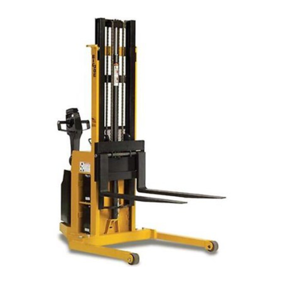
- Page 10 R3813 Figure 1-3 PDI Lift Truck PDI0404 https://forklift-manuals.jimdofree.com...
-
Page 11: Operation
SECTION 2 OPERATION Do not operate this truck unless you have been trained and authorized to do so. Read all warn- 1. SEE SUPPLEMENT 207 FOR TRANSISTOR ings and instructions in this manual and on the lift CONTROL HEAD USED ON TRUCKS SERIAL truck. -
Page 12: Before Operation
11. Observe applicable traffic regulations. Yield right WARNING: Periodic maintenance of this truck by a of way to pedestrians. Slow down and sound horn QUALIFIED TECHNICIAN is required. at cross aisles and wherever vision is obstructed. CAUTION: A QUALIFIED SERVICE TECHNICIAN 12. - Page 13 R5699 Figure 2-2 Sample of Operator Check List PDI0404 https://forklift-manuals.jimdofree.com...
-
Page 14: Power Drive Control Handle
2-4. POWER DRIVE CONTROL HANDLE. speed in the forward direction. Pressing the speed control farther closes a contact for second speed and 2-4.1. Control Handle. farther, third speed. Pressing the upper portion of the speed control governs the three reverse speeds in the Two triangular shaped speed controls provide for easy same manner. -
Page 15: Belly-Button Switch Guard
R3629 Figure 2-4 Steering Arm Braking Position To move forward, slowly press the lower portion of the direction of the lift truck to forward direction in low the speed control or rotate the grips downward. speed. Press the forward speed control or rotate the grips farther to increase speed. -
Page 16: Loading And Unloading
R5802 Figure 2-5 Lift/Lower Lever WARNING: Check the space above the mast and the Raise forks to desired height. Move truck into load to be sure that there is sufficient position so forks are within pallet or skid, and the room for raising the forks. -
Page 17: Planned Maintenance
Water level must cover plates but not be higher than accordingly. These procedures must be performed by the base of the battery cell filler neck. a qualified service technician or your Big Joe service representative. Table 3-1 Monthly and Quarterly Inspection and Service Chart... -
Page 18: 3-3.2. Timer Charger Operation
3-3.2. Timer Charger Operation. Truck Serial Number 342392 To 376499, reinstall and position battery retainer bar to prevent battery The batteries must be pulled out of the compartments movement in excess of 1/2". in order to check the specific gravity. Use the following procedure: Truck Serial Number 342392 To 376499, remove... -
Page 19: 3-3.3. Smart Charger Operation
3-3.3. Smart Charger Operation. Ultra-deep discharging of brand new batteries Big Joe "Smart" Chargers incorporate computer logic should be avoided for at least 15 cycles. To dramat- circuits to provide full automatic recharging and shut ically extend battery life, ultra-deep discharge should off operation for convenient overnight service. -
Page 20: 3-4.3. Removing Batteries From Charger
NOTE: The battery charger includes an override timer which terminates the charge if the cycle does not complete after 18 hours of charging. This time-out condition is indicated by the green LED flashing off and on, and it indi- cates a fault condition which should be inves- tigated. -
Page 21: Lubrication
With carriage fully lowered, spray or brush and rust and oxidation inhibitors. on a film of SAE 30 or 40 engine oil. Big Joe Part No.900855 (1 gallon) 900893 (1 quart) No. 4 SAE 30 or 40 Engine Oil... - Page 22 R5815 Figure 3-3 Lubrication Diagram Table 3-4 Lubrication Chart FIG 3-2 LOCATION METHOD OF TYPE APPLICATION INDEX APPLICATION (Table 3-3) LUBRICANT Hydraulic System — No. 3 With lift carriage fully lowered, fill Capacity-6 quarts reservoir with hydraulic oil to "FULL" mark on dip stick. Lift carriage rollers No.
-
Page 23: Troubleshooting
SECTION 4 TROUBLESHOOTING 4-1. GENERAL 1. SEE SUPPLEMENT 207 FOR TRANSISTOR Table 4-1 serves as a guide to determine possible CONTROL HEAD USED ON TRUCKS SERIAL causes of trouble. The table is divided into five main NUMBER 333375 TO 334630 categories: Truck Dead: Trouble With Travel: Trouble With Braking: Trouble With Lifting Or Lowering, and 2. - Page 24 Table 4-1 Troubleshooting Chart - Continued MALFUNCTION PROBABLE CAUSE CORRECTIVE ACTION Truck runs forward, but not in Defective speed control switch in Check for positive dc voltage at reverse. control head or defective contac- number 1 wire on reverse con- tor.
- Page 25 Table 4-1 Troubleshooting Chart - Continued MALFUNCTION PROBABLE CAUSE CORRECTIVE ACTION Oil splashes out of vent when low- Oil level too high. Drain, then refill reservoir to ering forks. "FULL" mark on dip stick. Squealing sounds when lifting a. Oil level too low. Add oil to reservoir.
- Page 26 Table 4-1 Troubleshooting Chart - Continued MALFUNCTION PROBABLE CAUSE CORRECTIVE ACTION Load will not hold. a. Oil bypassing internally Disassemble, clean, and reassem- between check ball and control ble. Replace worn parts as valve body. required. b. Worn lift cylinder packing. Replace cylinder packing.
-
Page 27: Smart Charger 004978 Troubleshooting
4-2. SMART CHARGER 004978 TROUBLESHOOT- mum output voltage. Incorrect setting of (Trucks Serial Number 344163 To 376499) this potentiometer can cause damage to the charger or batteries. The logic flow troubleshooting diagram provides a sim- plified means of isolating the probable cause for a WARNING: A jumper is used on the printed circuit problem by performing steps to obtain a "Yes"... - Page 28 1.Disconnect charger from battery 2.Connect charger to AC input power source Is 24 Is 24 VDC to 28 approximately VDC to 28 VDC present 48 VAC VDC present from YES Connect battery Is indicator between input to present across battery positive (+) side light turned on? to charger circuit breaker (two...
- Page 29 YES Disconnect AC input power to the charger Using an ohmmeter, Measure resistance check resistance from between side of Is resistance Ammeter faulty Is resistance negative side of ammeter connected greater than near 0 ohms? replace ammeter connector to chassis to charger and 100 Ohms ground.
-
Page 30: Optional Gel Cell Battery Charger 004987 Troubleshooting
4-3. OPTIONAL GEL CELL BATTERY CHARGER Verify 25 VAC from blue wire to each white 004987 TROUBLESHOOTING wire. (Trucks Serial Number 344163 To 376499) Verify 50 VAC from the white wire to white Refer to Figure 4-5 for part identification. Be sure the wire. - Page 31 R6132 Figure 4-5. Battery Charger Wiring Diagram PDI0404 https://forklift-manuals.jimdofree.com...
- Page 32 1. SEE SUPPLEMENT 187 FOR TRANSISTOR TRUCKS USED ON TRUCKS SERIAL NUMBER 333375 TO 338589 SERIAL NUMBERS 333375 TO 364407 2. SEE SUPPLEMENT 233 FOR TRANSISTOR TRUCKS SERIAL NUMBER 338590 TO 364407 R5816A Figure 4-6 Wiring Diagram (Sheet 1) 4-10 PDI0404 https://forklift-manuals.jimdofree.com...
- Page 33 1. SEE SUPPLEMENT 187 FOR TRANSISTOR TRUCKS USED ON TRUCKS SERIAL NUMBER 333375 TO 338589 SERIAL NUMBERS 333375 TO 364407 2. SEE SUPPLEMENT 233 FOR TRANSISTOR TRUCKS SERIAL NUMBER 338590 TO 364407 R5816B Figure 4-6 Wiring Diagram (Sheet 2) PDI0404 4-11 https://forklift-manuals.jimdofree.com...
- Page 34 1. SEE SUPPLEMENT 233 FOR TRANSISTOR TRUCKS USED ON TRUCKS SERIAL NUMBER 364408 TO 372811 SERIAL NUMBERS 364408 TO 376499 2. SEE SUPPLEMENT 349 FOR TRANSISTOR TRUCKS SERIAL NUMBER 372812 TO 376499 R6084A Figure 4-7 Wiring Diagram (Sheet 1) 4-12 PDI0404 https://forklift-manuals.jimdofree.com...
- Page 35 1. SEE SUPPLEMENT 233 FOR TRANSISTOR TRUCKS USED ON TRUCKS SERIAL NUMBER 364408 TO 372811 SERIAL NUMBERS 364408 TO 376499 2. SEE SUPPLEMENT 349 FOR TRANSISTOR TRUCKS SERIAL NUMBER 372812 TO 376499 R6084B Figure 4-7 Wiring Diagram (Sheet 2) PDI0404 4-13 https://forklift-manuals.jimdofree.com...
- Page 36 NOTES 4-14 PDI0404 https://forklift-manuals.jimdofree.com...
-
Page 37: Steering Arm And Control Heads Servicing
SECTION 5 STEERING ARM AND CONTROL HEADS SERVICING 5-2. COLD CONDITIONING. 1. SEE SUPPLEMENT 207 FOR TRANSISTOR The cold conditioning version of the truck differs from CONTROL HEAD USED ON TRUCKS SERIAL the standard model where necessary to improve per- NUMBER 333375 TO 334630 formance in cold temperatures. -
Page 38: Belly-Button Switch Adjustment
CAUTION: While removing the belly-button casting, two springs (needed for reassembly) will fall free. Being careful to catch and retain the belly-button springs (25, Figure 5-4) that may fall from the con- trol head (41) as the belly-button casting (42) is removed, drive out the roll pins (11) that secure the belly-button casting. -
Page 39: Control Head Assembly
1. SEE SUPPLEMENT 207 FOR TRANSISTOR CONTROL HEAD USED ON TRUCKS SERIAL NUMBER 333375 TO 334630 2. SEE SUPPLEMENT 220 FOR TRANSISTOR CONTROL HEAD USED ON TRUCKS SERIAL NUMBER 33461 TO 376499 R3837 Figure 5-4 Control Head Assembly PDI0404 https://forklift-manuals.jimdofree.com... -
Page 40: Control Head Switch Replacement
Repeat steps 2 through 5 until pressing the belly- Replace switch plate (18, Figure 5-5) and secure button casting actuates the switch properly. with four screws (15 and 16, Figure 5-4) on top and bottom of control handle (41, Figure 5-4). - Page 41 1. SEE SUPPLEMENT 207 FOR TRANSISTOR CONTROL HEAD USED ON TRUCKS SERIAL NUMBER 333375 TO 334630 2. SEE SUPPLEMENT 220 FOR TRANSISTOR CONTROL HEAD USED ON TRUCKS SERIAL NUMBER 33461 TO 376499 R3838 Figure 5-5 Push Button Switches PDI0404 https://forklift-manuals.jimdofree.com...
-
Page 42: Steering Arm Return Spring Adjustment
13. Observing through top cover opening, slide shaft tube (2) will rotate counterclockwise when screw (28) with tube (34) out left hand side of control is loosened. head just enough to clear return spring (24). With a pair of vise grip pliers, grip the flat surfaces 14. -
Page 43: Steering Arm And Electrical Cable
USED ON TRUCKS SERIAL NUMBERS 333375 TO 345826 345828 TO 345865 345871 TO 345389 HANDLE RETURN SPRING KIT PART NUMBER 901325 CONTAINS: ITEM R5806 Figure 5-6 Steering Arm and Electrical Cable Remove steering arm return spring (1) from 10. Slide spring tube assembly into pivot cap (3) and spring tube assembly (2). -
Page 44: Pivot Tube Flanged Bushing Replacement
5-8. PIVOT TUBE FLANGED BUSHING Disconnect the wire to the horn. REPLACEMENT. Disconnect the four cables connected to the drive motor. NOTE: Replacement flanged bushings requires the removal of the steering arm and Disconnect brake rod from brake lever by remov- pivot cap, transmission, and pivot tube ing cotter pin. - Page 45 12. Remove lower spacer mounting hardware as fol- 17. Alternately raise the truck frame and then the lows: pivot tube several more inches, until enough clearance is provided to lift out the transmission Truck Serial Number 339404 To 376499, assembly with the drive wheel and motor and remove set screw (14) from lower spacer (13) brake assembly.
-
Page 46: Electrical Control Cable Replacement
32. Align the mounting screw holes, and install the 5-9. ELECTRICAL CONTROL CABLE REPLACE- pivot tube onto the transmission with the four MENT. socket head screws (11). NOTE: Refer to Figure 5-9 while performing the fol- 33. Lower the truck frame fully and remove the lifting lowing procedure. - Page 47 R116 Figure 5-9 Electrical Control Cable Replacement PDI0404 5-11 https://forklift-manuals.jimdofree.com...
- Page 48 16. Connect the new cable connector (9) to the con- 22. Loop cable around spring tube assembly (3) as nector on the contactor panel. illustrated and push connector (8) end of cable through steering arm. 17. Route and connect cable wire numbers 3 and 8 to the dead man switch.
-
Page 49: Brake Servicing
SECTION 6 BRAKE SERVICING 6-1. ADJUSTMENT Disconnect battery connections. Jack up the truck so the drive wheel is off the If the mechanical brake does not begin to hold when ground; then securely block the truck to prevent the steering arm is raised or lowered into the lightly slipping. -
Page 50: Replacement Of Disc Brake Parts
Remove the cotter pin (4, Figure 6-2), then slide 16. Make sure that applying the brake activates the the rod (2) into the brake lever (3) far enough to switch but does not fully depress the switch pull the link pin (1) out of the lever (5). plunger. - Page 51 16. Align the bolt holes in the bracket (28) and brake assembly lightly with hammer, if necessary to pad (27), then slip the bolts (20) through the holes clear mounting plate opening. in brake pad (27), mounting block (11) and 19.
- Page 52 NOTES PDI0404 https://forklift-manuals.jimdofree.com...
-
Page 53: Transmission, Drive Wheel, Adjustable Straddle,And Load Wheel Servicing
SECTION 7 TRANSMISSION, DRIVE WHEEL, ADJUSTABLE STRADDLE, AND LOAD WHEEL SERVICING Completing the initial disassembly procedure provides NOTE: During reassembly, inspect parts for wear and access to any transmission parts requiring replace- replace as required. Be sure that washers (34 ment. - Page 54 R3851 Figure 7-1 Transmission PDI0404 https://forklift-manuals.jimdofree.com...
-
Page 55: Adjustable Straddle Lift Trucks
Remove disc assembly (7) from armature shaft of Set brake in locked position. motor. CAUTION: Do not raise truck higher than necessary NOTE: During reassembly, inspect parts for wear and for load wheels to clear floor when per- replace as required. Be sure bearing (8), O- forming next step or truck can flip over. -
Page 56: Load Wheels
7-6. LOAD WHEELS. NOTE: Refer to Figure 7-3 for the following proce- dure. Block the caster wheels and remaining load wheel securely, and set the brakes. Raise front end of lift truck with a jack or another lift truck. Place strong supports under straddle leg immediately in back of wheel housing so that the load wheel being replaced is held approximately one inch from the floor. -
Page 57: Elevation System Servicing
SECTION 8 ELEVATION SYSTEM SERVICING 8-1. GENERAL. Take up slack in both lift chains with hex nut (20, Figure 8-1, Figure 8-2 or 21, Figure 8-3) on the The elevation system includes the outer mast, inner adjusting bolt. Strive for equal tension on chains. mast (telescopic and full free lift models), lift carriage, Align adjusting bolts so each clevis pin is parallel lift chains, lift cylinder, and ram head. -
Page 58: 8-2.2. Full Free Lift
USED ON TRUCKS SERIAL NUMBERS 333375 TO 338205 R5829 Figure 8-2 Elevation System (Telescopic) 8-2.2. Full Free Lift. Test chain by operating carriage. If slack is still apparent, repeat above procedure. Lower carriage (31, Figure 8-4) fully, then discon- nect battery. 8-3. -
Page 59: Lift Chain Replacement
R1752 Figure 8-3 Elevation System (Non-Telescopic) 8-4. LIFT CHAIN REPLACEMENT. Remove cotter pin (16, Figure 8-1, Figure 8-2 Figure 8-3) and clevis pin (14, Figure 8-1, Fig- 8-4.1. Telescopic and Non-Telescopic. ure 8-2 or 16, Figure 8-3) from chain adjusting bolt (17, Figure 8-1,... -
Page 60: Elevation System (Full Free Lift)
R5830 Figure 8-4 Elevation System (Full Free Lift) PDI0404 https://forklift-manuals.jimdofree.com... -
Page 61: 8-4.2. Full Free Lift
8-4.2. Full Free Lift. Remove cap screw and lock washer (3 and 4) and lift ram head (5) from lift cylinder (1). Place a solid block on floor under the vertical Remove screw (15), lock washer (12) and plain members nearest the center of the lift carriage. washer (14) from base of cylinder (1). -
Page 62: 8-5.3. Full Free Lift
WARNING: Support lift cylinder before performing 10. Remove the yoke sheaves as described in para- the following steps to prevent cylinder graph 8-7. from falling. NOTE: Disassembly of lift cylinder is covered in SEC- 10. Tilt lift cylinder (24) and ram head (25) forward TION from their position in the lift truck. -
Page 63: Yoke Sheave Replacement (Full Free Lift)
8-7. YOKE SHEAVE REPLACEMENT (FULL FREE Adjust lift chains as described in paragraph 8-2. LIFT). 8-8. LUBRICATION OF MAST. WARNING: Make certain power is disconnected before attempting to remove ram head. NOTE: Refer to Figure 8-1, Figure 8-2 Figure 8-3. Lower the lift carriage fully. - Page 64 NOTES PDI0404 https://forklift-manuals.jimdofree.com...
-
Page 65: Hydraulic System Servicing
SECTION 9 HYDRAULIC SYSTEM SERVICING 9-1. RELIEVING SYSTEM PRESSURE. 9-2. FLOW CONTROL VALVE REPLACEMENT. WARNING: Hydraulic system pressure must be NOTE: Figure 9-2 Figure 9-3 show the relation- relieved before removing hydraulic sys- ship of all components in the hydraulic sys- tem components. -
Page 66: Suction Line Filter Replacement
The chains will become slack and 12. Check oil level on dip stick. If low, fill to ``FULL'' need not be removed. mark on dip stick with Big Joe hydraulic oil part NOTE: A small amount of hydraulic oil will drain from number 900855. - Page 67 R5821 Figure 9-3 Hydraulic System (Full Free Lift) PDI0404 https://forklift-manuals.jimdofree.com...
-
Page 68: Line Or Fitting Replacement
Re-install the drain plug. used to set the valve for lowering and the NOTE: Refill only with Big Joe hydraulic oil part num- hydraulic pump switch for lifting. ber 900855 and only while carriage is fully... -
Page 69: 9-5.2. Disassembly
With a screwdriver in slot of release cam, rotate 1/ NOTE: Disconnecting of wires is not necessary. 8 turn clockwise. This is to make sure check ball is Disconnect tubing (22, Figure 9-2 or 15, Figure 9- seated in valve seat. 3) from lift/lower control valve (9, Figure 9-2 or 11,... -
Page 70: 9-5.3. Pump Motor Switch Adjustment
13. To reassemble, install O-ring (2, Figure 9-5 Fig- 9-6.1. Pump and Motor Assembly Removal. 9-6) and release cam (3) onto valve body (1). WARNING: Before disconnecting any hydraulic lines, 14. Install switch bracket (4) onto valve body (1) with make sure the forks are lowered com- two screws (5). -
Page 71: Lift Cylinder Repair
9-7. LIFT CYLINDER REPAIR. 9-7.2. Telescopic. NOTE: Removal procedures are covered in SEC- 9-7.1. Non-Telescopic. TION NOTE: Removal procedures are covered in SEC- CAUTION: To prevent cylinder damage, use proper TION pipe clamp vise. The cylinder will be dis- CAUTION: To prevent cylinder damage, use proper torted if the vise is tightened too much. - Page 72 RETROFIT KIT PACKING KIT PART NUMBER PART NUMBER 907124 CONTAINS: 907123 CONTAINS: ITEM ITEM USED ON TRUCKS SERIAL NUMBERS 333375 TO 338205 R6107 R6106 Figure 9-7 Lift Cylinder (Non-Telescopic) PDI0404 https://forklift-manuals.jimdofree.com...
- Page 73 PACKING KIT USED ON TRUCKS PART NUMBER SERIAL NUMBERS 907123 CONTAINS: 333375 TO 353212 ITEM RETROFIT KIT PART NUMBER 907124 CONTAINS: ITEM R5812 Figure 9-8 Lift Cylinder (Telescopic) PDI0404 https://forklift-manuals.jimdofree.com...
-
Page 74: 9-7.3. Full Free Lift
9-7.3. Full Free Lift. Assemble FFL center cylinder by reversing the disassembly procedure. For ease of assembly NOTE: Removal procedures are covered in SEC- when assembling threaded parts, apply a coating TION of white lead replacement to the threads--except for the threads of the cylinder base (9) which are CAUTION: To prevent cylinder damage, use proper to be coated with Loctite 222 adhesive (24). - Page 75 (4) Coat rings and seals with hydraulic fluid (5) Assembly FFL outer cylinder(s) by during replacement. reversing the disassembly procedure. For ease of assembly, when assembling threaded parts, apply a coating of white lead replacement to the threads. PACKING KIT PART NUMBER 900949 CONTAINS: ITEM...
- Page 76 NOTES 9-12 PDI0404 https://forklift-manuals.jimdofree.com...
-
Page 77: Electrical Components
SECTION 10 ELECTRICAL COMPONENTS 10-1.ELECTRICAL CONTROL PANELS. 10-2.CONTROL PANEL SERVICING. Truck Serial Number 333375 to 364407: Figure 10-1 identifies parts associated with the com- 1. SEE SUPPLEMENT 187 FOR TRANSISTOR plete electrical control panel assembly. CONTROLLER USED ON TRUCKS SERIAL Truck Serial Number 364408 To 376499: NUMBER 333375 TO 338589 Figure 10-2... - Page 78 USED ON TRUCKS 1. SEE SUPPLEMENT 233 FOR TRANSISTOR SERIAL NUMBERS CONTROLLER USED ON TRUCKS SERIAL 364408 TO 376499 NUMBER 364408 TO 372811 2. SEE SUPPLEMENT 349 FOR TRANSISTOR CONTROLLER USED ON TRUCKS SERIAL NUMBER 372812 TO 376499 R6083 Figure 10-2 Electrical Control Panel 10-2 PDI0404 https://forklift-manuals.jimdofree.com...
-
Page 79: Serial Number 333375 To 364407
10-3.Contactor Servicing. Serial Number 333375 to Coil can now be removed from frame (2) by 364407. removing 3/4 inch long hex head screw and flat washer. NOTE: One contactor tip kit part number 900531-02 contains the number of contacts required to 10-3.2.2nd and 3rd Speed Contactor service all contactors on a truck. -
Page 80: 10-3.3.Forward-Reverse Contactor
USED ON TRUCKS SERIAL NUMBERS 333375 TO 364407 CONTACTOR TIP KIT PART NUMBER 900531-08 CONTAINS: ITEM R1865 Figure 10-3 Contactor (2nd and 3rd Speed) Part Number 005659 10-3.3.Forward-Reverse Contactor Disassembly. Slide braid assembly (3) off contact (8) and (Refer to Figure 10-4) Serial Number 333375... -
Page 81: 10-3.4.Forward-Reverse Contactor
USED ON TRUCKS SERIAL NUMBERS 333375 TO 364407 CONTACTOR TIP KIT PART NUMBER 900531-09 CONTAINS: ITEM R1866 Figure 10-4 Contactor (Forward-Reverse) Part Number 005657 10-3.4.Forward-Reverse Contactor Reassembly. Place contactor on work surface with base mold- (Refer to Figure 10-4) Serial Number 333375 ing down. -
Page 82: Battery Charger 004967-01 And 004967-02 Schematic
10-4.PUMP MOTORS. 10-6.BATTERY CHARGER. Refer to applicable Figure 12-29, Figure 12-30, Figure The PDI battery charger is mounted in the upper right 12-31 Figure 12-32 for motor disassembly. Pumps side of the truck as shown in Figure 12-38 Figure are replaceable but not repairable. When replacing 12-39. -
Page 83: Battery Charger 004976-01 Schematic
R5280 Figure 10-6 Battery Charger 004976-01 Schematic 120 V AC MALE OUTLET PLUG FLANGED AMMETER CHARGER CONNECTOR FUSE CIRCUIT BREAKER INDICATOR LOGIC BRD SINK HEAT SINK LOGIC BOARD TRANSF (120 VAC) AUTOMATIC CHARGER R5962 Figure 10-7 Battery Charger 004978 Schematic PDI0404 10-7 https://forklift-manuals.jimdofree.com... -
Page 84: Batteries
10-7.BATTERIES. Truck Serial Number 334289 to 342391, remove two nuts (22), two lockwashers (21), NOTE: Batteries are removed from the right side of two bolts (18) and two handle rods (20). the truck (see Figure 10-8). When installing a Truck Serial Number 333375 to 334288, new battery, be sure handles are securely remove four screws (25) and four lockwash-... -
Page 85: Base, Frame And Electrical Components
R5809 Figure 10-8 Base, Frame and Electrical Components PDI0404 10-9 https://forklift-manuals.jimdofree.com... -
Page 86: Electrical Components
10-9.HIGH SPEED LIMIT SWITCH. Position bracket with new switch in place on frame, and secure with washer (2), lockwasher Disconnect wiring from high speed limit switch (5, (3), and nut (4). Figure 10-9), then remove nut (4), lockwasher (3), Reconnect wiring to switch. and washer (2) securing switch mounting bracket (1) to frame. -
Page 87: Optional Equipment
SECTION 11 OPTIONAL EQUIPMENT 11-1.KEYSWITCH Numbers in parenthesis are parts list item number for Figure 12-46. Those trucks which have a keyswitch installed will have the wiring modified. The modification is shown in 11-5.1.PUSHBUTTON BOX REMOTE CONTROL Figure 12-42 and the schematic diagram Figure 4-6 Add solenoid to pump. - Page 88 NOTES 11-2 PDI0404 https://forklift-manuals.jimdofree.com...
-
Page 89: Illustrated Parts Breakdown
SECTION 12 ILLUSTRATED PARTS BREAKDOWN Following is an illustrated parts breakdown of assemblies and parts associated with the PDI Lift Truck. PDI0404 12-1 https://forklift-manuals.jimdofree.com... - Page 90 1. SEE SUPPLEMENT 207 FOR Figure 12-2 TRANSISTOR CONTROL HEAD FOR SWITCHES USED ON TRUCKS SERIAL Figure 12-3 NUMBER 333375 TO 334630 FOR COLD CONDITIONING 2. SEE SUPPLEMENT 220 FOR TRANSISTOR CONTROL HEAD USED ON TRUCKS SERIAL NUMBER 33463 TO 376499 R3837 Figure 12-1 Control Head Assembly 12-2...
- Page 91 INDEX PART INDEX PART PART NAME REQD. PART NAME REQD. 070486 ROUND HD. SLOTTED — 505050-04 CONTROL HEAD STANDARD MACHINE SCREW — 505050-05 CONTROL HEAD REMOTE LIFT 072400-01 HEX HD. SLOTTED SCREW, IN HANDLE 6-32 X 1/2 — 505050-06 CONTROL HEAD REMOTE LIFT 072415 PAN HD.
-
Page 92: Push Button Switches, Control Head
R3838 Figure 12-2 Push Button Switches, Control Head INDEX PART INDEX PART PART NAME REQD. PART NAME REQD. 056619-01 HORN DECAL 005643 CONTACT PIN 2 MAX. 056619-03 LIFT DECAL 005649 CONNECTOR 056619-04 LOWER DECAL 020697 PUSHBUTTON SWITCH 2 MAX. 067415 PAN HD. -
Page 93: Cold Conditioning, Control Head
R3966 Figure 12-3 Cold Conditioning, Control Head INDEX PART INDEX PART PART NAME REQD. PART NAME REQD. 077204 LOCKWASHER 018909 RESISTORS 072400-01 SCREW 068186 SCREW 059632 NUT, HEX, 5-40 023014 WIRE 400044 BRACKET THERMAL CUTOUT 400544 BRACKET, RESISTOR 020736 THERMAL CUTOUT SWITCH 018214 INSULATOR, SWITCH 005643... - Page 94 USED ON TRUCKS SERIAL NUMBERS 333375 TO 345826 345828 TO 345865 345871 TO 345389 HANDLE RETURN SPRING KIT PART NUMBER 901325 CONTAINS: ITEM R5806 Figure 12-4 Steering Arm and Electrical Cable 12-6 PDI0404 https://forklift-manuals.jimdofree.com...
- Page 95 INDEX PART INDEX PART PART NAME REQD. PART NAME REQD. 060300 . CLEVIS PIN — 505765-02* CONTROL ARM ASSY 056200 . CLEVIS 075060** . SPRING, RETURN 063478 . SCREW, HEX CAP, 1/4-20 X 3/4 501371** . SPRING TUBE 504364 . CLAMP ASSY 402455* .
- Page 96 USED ON TRUCKS SERIAL NUMBERS 333375 TO 339404 R5807 Figure 12-5 Pivot Tube Assembly INDEX PART INDEX PART PART NAME REQD. PART NAME REQD. 505683-01*** PIVOT TUBE WELDMENT (SEE 053108 BUSHING NOTE 1) 061000 ROLL PIN 504574** PIVOT TUBE WELDMENT (SEE 401695 SPACER NOTE 2)
- Page 97 NOTES PDI0404 12-9 https://forklift-manuals.jimdofree.com...
-
Page 98: Brake And Linkage
R6110 Figure 12-6 Brake and Linkage 12-10 PDI0404 https://forklift-manuals.jimdofree.com... - Page 99 INDEX PART INDEX PART PART NAME REQD. PART NAME REQD. 800188 LINK PIN 053109 LOCK BUSHING 052821 DISC BRAKE PAD ASSEMBLY 060417 COTTER PIN, 3/32 X 3/4 059421 . NUT 053106 FLANGED BUSHING 901189 . BOLT 111104 UPPER PIVOT PLATE 901190 .
- Page 100 R3851 Figure 12-7 Transmission 12-12 PDI0404 https://forklift-manuals.jimdofree.com...
- Page 101 INDEX PART INDEX PART PART NAME REQD. PART NAME REQD. 057256 . GEAR AND SHAFT — DRIVE MOTOR (FIGURE 12-8) 057241 . GEAR 063557 BOLT, 5/16-18 X 1-1/4 053031 . THRUST BEARING 077210 WASHER, SPLIT, 5/16 051204 . BEARING 403181 MOTOR PLATE 051203 .
-
Page 102: Drive Motor 016046
USED ON TRUCKS SERIAL NUMBERS 333375 TO 371793 R646 Figure 12-8 Drive Motor 016046 INDEX PART INDEX PART PART NAME REQD. PART NAME REQD. 901268 . TERMINAL KIT — 016046* DRIVE MOTOR — . LOCK WASHER, 1/4 901264 . FIELD COIL SET —... -
Page 103: Drive Motor 016052
USED ON TRUCKS SERIAL NUMBERS 371794 TO 376499 R6109 Figure 12-9 Drive Motor 016052 INDEX PART INDEX PART PART NAME REQD. PART NAME REQD. 900451 . FIELD RING — 016052 DRIVE MOTOR ASSY 901267 . BRUSH SET 907176 . ARMATURE 901268 . -
Page 104: Base And Frame
R5808 Figure 12-10 Base and Frame 12-16 PDI0404 https://forklift-manuals.jimdofree.com... - Page 105 INDEX PART INDEX PART PART NAME REQD. PART NAME REQD. 402236 SPACER — BASE AND FRAME 025713 GREASE FITTING 504579 SCREEN 504570 COVER 077030 WASHER, FLAT NO. 10 060106 SOUNDPROOF PAD 077209 WASHER, SPLIT, LOCK, 1/4 077031 WASHER, FLAT 059421 NUT, HEX, 1/4-20 077207 WASHER EXT TOOTH NO.
-
Page 106: Decal Location
R5818 Figure 12-11 Decal Location INDEX PART INDEX PART PART NAME REQD. PART NAME REQD. 056625 WARNING DECAL 056478 LIFT-LOWER DECAL 056626 OIL LEVEL 056499 NO RIDING DECAL 056595 CASTING LOGO 056564 CAUTION DECAL 056596-08 INSERT PDI 056494 CAUTION DECAL 056646 INSTR-CHARGER 056632... -
Page 107: Adjustable Straddle Frame
R3828 Figure 12-12 Adjustable Straddle Frame INDEX PART PART NAME REQD. 504696-01* RIGHT HAND STRADDLE 505347-01** RIGHT HAND STRADDLE (PDI 2024) LOAD WHEEL AND AXLE KIT 505347-02** RIGHT HAND STRADDLE PART NUMBER 901326 (PDI 2018) CONTAINS: 505788-01*** RIGHT HAND STRADDLE (PDI 2024) ITEM 505788-02*** RIGHT HAND STRADDLE... -
Page 108: Elevation System (Telescopic)
USED ON TRUCKS SERIAL NUMBERS 338206 TO 376499 R5822 Figure 12-14 Elevation System (Telescopic) 12-20 PDI0404 https://forklift-manuals.jimdofree.com... - Page 109 INDEX PART INDEX PART PART NAME REQD. PART NAME REQD. 060402 COTTER PIN INNER MAST 402051 ADJUSTING BOLT — NOT USED 059545 JAM NUT — NOT USED 077215 WASHER, LOCK — NOT USED 059445 NUT, HEX — NOT USED — 063603 HEX HD CAP SCREW NOT USED...
- Page 110 USED ON TRUCKS SERIAL NUMBERS 333375 TO 338205 R5829 Figure 12-15 Elevation System (Telescopic) 12-22 PDI0404 https://forklift-manuals.jimdofree.com...
- Page 111 INDEX PART INDEX PART PART NAME REQD. PART NAME REQD. 059545 JAM NUT INNER MAST 077215 WASHER, LOCK 501297 ROLLER BEARING AND HOUS- 059445 NUT, HEX 100021 SHIM 063603 HEX HD CAP SCREW 245736 SHIM 077211 WASHER, LOCK 077410 WASHER, LOCK, 3/8 077076 WASHER, FLAT —...
- Page 112 R1752 Figure 12-16 Elevation System (Non-Telescopic) 12-24 PDI0404 https://forklift-manuals.jimdofree.com...
- Page 113 INDEX PART INDEX PART PART NAME REQD. PART NAME REQD. 060402 COTTER PIN — LIFT CYLINDER (Figure 12-21) 402051 ADJUSTING BOLT 402034 CHAIN (60 IN. LIFT - 3.86 FT) (72 IN. LIFT - 4.86 FT) 059545 JAM NUT (84 IN. LIFT - 5.86 FT) 077215 WASHER, LOCK 064709...
- Page 114 R5830 Figure 12-17 Elevation System (Full Free Lift) 12-26 PDI0404 https://forklift-manuals.jimdofree.com...
- Page 115 INDEX PART INDEX PART PART NAME REQD. PART NAME REQD. 901365 ROLLER ASSEMBLY 053000 SHIM — 051102 . BEARING 053001 SHIM — 062325 . ROLLER 053002 SHIM 061023 ROLL PIN, 5/16 X 3/4 053003 SHIM — LIFT CYLINDER (Figure 12-23) 901366 ROLLER ASSEMBLY 060402...
-
Page 116: Lift Carriage And Forks
R1753 Figure 12-18 Lift Carriage and Forks 12-28 PDI0404 https://forklift-manuals.jimdofree.com... - Page 117 INDEX PART INDEX PART PART NAME REQD. PART NAME REQD. 296401 SHAFT, 24 IN WIDE CARRIAGE LIFT CARRIAGE, RIGID FORK, 1 INCH RING CHART 1 276605 SHAFT, 24 IN WIDE CARRIAGE LIFT CARRIAGE, FOR 1-1/4 INCH RINGS (TELE- CHART 2 ADJUSTABLE FORK SCOPIC AND FORKS PDI-2018...
-
Page 118: Hydraulic System (Telescopic And
R1750 Figure 12-19 Hydraulic System (Telescopic and Non-Telescopic) INDEX PART INDEX PART PART NAME REQD. PART NAME REQD. 035107 FILTER ASSY 504575 RESERVOIR 056110 CLAMP 504578 BREATHER & DIPSTICK 290000 TUBING 025501 ELBOW 025113 ADAPTER 282500 TUBING 025124 ADAPTER 070476 SCREW, HEX 1/4-20 1/2 °... -
Page 119: Hydraulic System (Full Free Lift)
R5821 Figure 12-20 Hydraulic System (Full Free Lift) INDEX PART INDEX PART PART NAME REQD. PART NAME REQD. 035106 FILTER ASSEMBLY 077209 WASHER, LOCK, 1/4 056110 CLAMP 505433 RESERVOIR 290000 TUBING 070476 SCREW, HEX 1/4-20 1/2 025113 ADAPTER 077031 WASHER, FLAT 025536 ELBOW 077211... -
Page 120: Lift Cylinder (Non-Telescopic)
RETROFIT KIT PACKING KIT PART NUMBER PART NUMBER 907124 CONTAINS: 907123 CONTAINS: ITEM ITEM USED ON TRUCKS SERIAL NUMBERS 333375 TO 338205 R6107 R6106 Figure 12-21 Lift Cylinder (Non-Telescopic) 12-32 PDI0404 https://forklift-manuals.jimdofree.com... - Page 121 LIFTING HEIGHT (INCHES) INDEX NO. PART NAME PART NO. PART NO. PART NO. — HYD. LIFT CYLINDER ASSY 500773 500774 500775 — — — . TUBE . WIPER RING 049508 049508 409508 . GLAND NUT 800023 800023 800023 . TOP O-RING 042122 042122 042122...
- Page 122 PACKING KIT USED ON TRUCKS PART NUMBER SERIAL NUMBERS 907138 CONTAINS: 333375 TO 353212 ITEM RETROFIT KIT PART NUMBER 907139 CONTAINS: ITEM R5812 Figure 12-22 Lift Cylinder (Telescopic) 12-34 PDI0404 https://forklift-manuals.jimdofree.com...
- Page 123 LIFT HEIGHT (INCHES) INDEX PART NAME PART NO. PART NO. PART NO. PART NO. PART NO. — HYD. LIFT CYLINDER ASSY 503600 503601 503602 503603 503604 . TUBE 503605 503606 503607 503608 503609 . WIPER RING 049508 049508 049508 049508 049508 .
-
Page 124: Lift Cylinders (Full Free Lift)
PACKING KIT PART NUMBER 900949 CONTAINS: ITEM R1583 Figure 12-23 Lift Cylinders (Full Free Lift) 12-36 PDI0404 https://forklift-manuals.jimdofree.com... - Page 125 INDEX PART INDEX PART PART NAME REQD. PART NAME REQD. 401642 . PISTON, 2.5 DIA. — 503996-01 FFL CYLINDER ASSEMBLY 106 IN. LIFT HEIGHT 503992-01 . CYLINDER ROD, 106 LIFT HT — 503996-02 FFL CYLINDER ASSEMBLY 503992-02 . CYLINDER ROD, 130 LIFT HT 130 IN.
-
Page 126: Part Number 005659
BALL CHECK KIT BALL CHECK KIT PART NUMBER PART NUMBER 900132 CONTAINS: 900132 CONTAINS: ITEM ITEM R1755 Figure 12-25 Lift Control Valve R1809 (Cold Conditioning) Figure 12-24 Lift Control Valve (Standard) INDEX PART PART NAME REQD. INDEX PART — 503209-02 LIFT CONTROL VALVE ASSY PART NAME REQD. - Page 127 NOTES PDI0404 12-39 https://forklift-manuals.jimdofree.com...
-
Page 128: Batteries
R5809 Figure 12-26 Batteries 12-40 PDI0404 https://forklift-manuals.jimdofree.com... - Page 129 INDEX PART INDEX PART PART NAME REQD. PART NAME REQD. 504609† CONNECTOR AND CABLE ASSY 070488 SCREW, RD HD, 1/4-20 X 3/8 FROM BATTERY TO 077209 WASHER, SPLIT, LOCK, 1/4 BATTERY 077105 WASHER, FLAT BRASS 063566*** BOLT, 5/16-18 X 5-1/2 008918 FUSE, 120 AMP 402262***...
-
Page 130: Quick Disconnect Cable Installation
R5695 Figure 12-27 Quick Disconnect Cable Installation INDEX PART PART NAME REQD. — 505632 QUICK DISCONNECT CABLE KIT 505630 CONNECTOR ASSEMBLY BATTERY 505631 CONNECTOR ASSEMBLY BATTERY 505649 CORD ASSY-CHARGING, EXTERNAL 12-42 PDI0404 https://forklift-manuals.jimdofree.com... - Page 131 NOTES PDI0404 12-43 https://forklift-manuals.jimdofree.com...
- Page 132 1. SEE SUPPLEMENT 187 FOR TRANSISTOR CONTROLLER USED ON TRUCKS SERIAL NUMBER 333375 TO 338589 2. SEE SUPPLEMENT 233 FOR TRANSISTOR CONTROLLER USED ON TRUCKS SERIAL NUMBER 338590 TO 372811 3. SEE SUPPLEMENT 233 FOR TRANSISTOR CONTROLLER USED ON TRUCKS SERIAL NUMBER 372812 TO 376499 R5810...
- Page 133 INDEX PART INDEX PART PART NAME REQD. PART NAME REQD. 020729 SWITCH 402255 BRACKET 077204 WASHER, LOCK NO. 6 077030 WASHER, FLAT NO. 10 068179 SCREW, RD, 5-40 X 5/8 077207 LOCK WASHER NO. 10 018911 RESISTOR 059416 NUT, HEX, 10-32 402256 BRACKET 020673...
-
Page 134: Hydraulic Pump And Motor 905046
USED ON TRUCKS SERIAL NUMBERS 333375 TO 341643 R1990 Figure 12-29 Hydraulic Pump and Motor 905046 INDEX PART INDEX PART PART NAME REQD. PART NAME REQD. 905032 . . STUD PACKAGE — 016911 PUMP AND MOTOR ASSEMBLY 905033 . . PROTECTIVE CAP —... -
Page 135: Hydraulic Pump And Motor Assembly 016935
USED ON TRUCKS SERIAL NUMBERS 341644 TO 360730 EXCEPT 359732, 359733, 359738, 360545, 360546, 360547, 360549, 360550, 360551, 360572, 360619, 360623, 360633, 360634, 360723, 360727 USED ON TRUCKS SERIAL NUMBERS 341644 TO 353859 R5304 R6180 Figure 12-30 Hydraulic Pump and Motor Assembly 016935 INDEX PART INDEX... -
Page 136: Hydraulic Pump And Motor Assembly 016942
USED ON TRUCKS SERIAL NUMBERS 367402, 367404, 367406, 367408, 367409, 367410, 367411, 367412, 367413, 367414, 367416, 367417, 367418, 367419, 367432, 367463, 367464, 368852, 368853, 368855, 368878, 368900, 368930, 368931, 368933, 368934, 368935, 368956, 370267, 370281, 370282, 370285, 370292, 370305, 370306, 370307, 370313, 370318, 370358, AND 37036 R6094 Figure 12-31 Hydraulic Pump and Motor Assembly 016942 INDEX... -
Page 137: Hydraulic Pump And Motor Assembly 016940
USED ON TRUCKS SERIAL NUMBERS 359732, 359733, 359738, 360545, 360546, 360547, 360549, 360550, 360551, 360572, 360619, 360623, 360633, 360634, 360723, 360727, 360730 TO 376499 EXCEPT 367402, 367404, 367406, 367408, 367409, 367410, 367411, 367412, 367413, 367414, 367416, 367417, 367418, 367419, 367432, 367463, 367464, 368852, 368853, 368855, 368878, 368900, 368930, 368931, 368933, 368934, 368935, 368956, 370267, 370281, 370282, 370285, 370292, 370305, 370306, 370307, 370313, 370318, 370358, AND 37036 OUTPUT... -
Page 138: Electrical Control Panel
USED ON TRUCKS SERIAL NUMBERS 333375 TO 364407 1. SEE SUPPLEMENT 187 FOR TRANSISTOR CONTROLLER USED ON TRUCKS SERIAL NUMBER 333375 TO 338589 2. SEE SUPPLEMENT 233 FOR TRANSISTOR CONTROLLER USED ON TRUCKS SERIAL NUMBER 338590 TO 364407 R3836 Figure 12-33 Electrical Control Panel INDEX PART INDEX... - Page 139 USED ON TRUCKS SERIAL NUMBERS 364408 TO 376499 1. SEE SUPPLEMENT 233 FOR TRANSISTOR CONTROLLER USED ON TRUCKS SERIAL NUMBER 364408 TO 372811 2. SEE SUPPLEMENT 233 FOR TRANSISTOR CONTROLLER USED ON TRUCKS SERIAL NUMBER 372812 TO 376499 R6083 Figure 12-34 Electrical Control Panel INDEX PART INDEX...
-
Page 140: Contactor (Forward/Reverse)
BALL CHECK KIT BALL CHECK KIT USED ON TRUCKS USED ON TRUCKS PART NUMBER PART NUMBER SERIAL NUMBERS SERIAL NUMBERS 900531-09 900531-08 333375 TO 364407 333375 TO 364407 CONTAINS: CONTAINS: ITEM ITEM R1866 R1865 Figure 12-35 Contactor (2nd and 3rd Speed) Figure 12-36 Contactor (Forward/Reverse) INDEX PART... -
Page 141: Indicator
USED ON TRUCKS SERIAL NUMBERS 344163 TO 376499 R5297 Figure 12-37 "Smart" Battery Charger Installation INDEX PART INDEX PART PART NAME REQD. PART NAME REQD. 059412 NUT, HEX, 6-32 065476 SCREW, HEX HD 057515 GROMMET 077209 WASHER, LOCK, 1/4 split 505640 CONNECTOR ASSEMBLY 059421... - Page 142 USED ON TRUCKS SERIAL NUMBERS 344163 TO 376499 R6118 Figure 12-38 Gel Cell Battery Charger INDEX PART INDEX PART PART NAME REQD. PART NAME REQD. 505992 BRACKET, CHARGER — 004987 CHARGER KIT-24V, 25 AMP 077209 WASHER-LOCK, SPLIT, 1/4 904075 . PCB ASSY WITH HEATSINK 077421 NUT-HEX, 1/4-20 904074...
-
Page 143: Battery Chargers
USED ON TRUCKS SERIAL NUMBERS 333375 TO 344162 R1758 Figure 12-39 Battery Charger Mounting INDEX PART INDEX PART PART NAME REQD. PART NAME REQD. 005454 CONNECTOR, INLET FLANGE, — BATTERY CHARGER (Figure 12- 120 VAC Figure 12-41) 005455 CONNECTOR, INLET FLANGE, 065476 SCREW, HEX HD, 1/4-20 X 1/2 240 VAC (OPTIONAL) - Page 144 USED ON TRUCKS SEE SUPPLEMENT SERIAL NUMBERS 304 FOR ADDITIONAL 333375 TO 344162 INFORMATION R5281 Figure 12-40 Optional "Smart" Charger 004976-01 (Replaces Timer Charger 004967-01) INDEX PART INDEX PART PART NAME REQD. PART NAME REQD. 907077 . TRIAC (CONTROL CARD) —...
- Page 145 USED ON TRUCKS SEE SUPPLEMENT SERIAL NUMBERS 302 FOR ADDITIONAL 333375 TO 344162 INFORMATION R3025 Figure 12-41 Standard Timer Battery Charger 004967-01 and 004967-02 INDEX PART INDEX PART PART NAME REQD. PART NAME REQD. — 004967-02 BATTERY CHARGER, — 004967-01 BATTERY CHARGER, 240 V, 50 HZ (OPTIONAL) 120 V, 60 HZ (STANDARD)
- Page 146 SUPPLEMENT 233 FOR TRANSISTOR TRUCKS SERIAL NUMBER 338590 TO 376499 R1760 Figure 12-42 Optional Keyswitch INDEX PART R1761 PART NAME REQD. 020725 SWITCH, KEY Figure 12-43 Optional Hour Meter 021203 TERMINAL, RING NO. 10 INDEX PART 005627 CONTACT PART NAME REQD.
-
Page 147: Optional Battery Capacitor Indicator
OLDER VERSION R1776 Figure 12-44 Optional Battery Capacitor Indicator INDEX PART INDEX PART PART NAME REQD. PART NAME REQD. 005626 CONTACTS, MALE 010619-02 METER, BATTERY CAPACITY, 24 V W/O LIFT LOCKOUT 068177 SCREW, RD HD, 5-40 X 3/8 010624-02 METER, BATTERY CAPACITY, 077203 WASHER, LOCK, SPLIT, NO. - Page 148 NEWER VERSION R5819 Figure 12-45 Optional Battery Capacitor Indicator INDEX PART INDEX PART PART NAME REQD. PART NAME REQD. 005627 CONTACT AMP 010617-02 METER, BATTERY CAPACITY, 24 V W/O LIFT LOCKOUT 005647 CONNECTOR 010618-02 METER, BATTERY CAPACITY, 005626 CONTACTS, MALE 24 V W/LIFT LOCKOUT 021204 TERMINAL, FEMALE...
-
Page 149: Optional Remote Control Installation
R1777 Figure 12-46 Optional Remote Control Installation INDEX PART INDEX PART PART NAME REQD. PART NAME REQD. 077203 WASHER, LOCK, SPLIT, NO. 5 021203 TERMINAL, RING 8-10 STUD 059410 NUT, HEX 5-40 048133 SOLENOID, 24 V 017800 PLUG, FEMALE, FLUSH MOUNT 021718 TERMINAL, SLIP ON, 1/4 INSULATED... - Page 150 NOTES 12-62 PDI0404 https://forklift-manuals.jimdofree.com...
- Page 151 https://forklift-manuals.jimdofree.com...
- Page 152 Big Joe Manufacturing Company https://forklift-manuals.jimdofree.com...
Need help?
Do you have a question about the PDI Series and is the answer not in the manual?
Questions and answers