Table of Contents
Advertisement
Quick Links
CB33
SELF-PROPELLED,
POWER STEERING
COUNTERBALANCED LIFT TRUCK
Operation
Maintenance
Repair Parts List
NOTE: For the most current parts information and service updates, please refer to the Big Joe
Support site at
www.bigjoesupport.com
Big Lift LLC
MANUAL NO. BL-CB33-0115 - 03-01-2018
www.bigjoeforklifts.com
Advertisement
Table of Contents
Troubleshooting

Related Manuals for Big Joe CB33


Summary of Contents for Big Joe CB33
- Page 1 SELF-PROPELLED, POWER STEERING COUNTERBALANCED LIFT TRUCK Operation Maintenance Repair Parts List NOTE: For the most current parts information and service updates, please refer to the Big Joe Support site at www.bigjoesupport.com Big Lift LLC MANUAL NO. BL-CB33-0115 - 03-01-2018 www.bigjoeforklifts.com...
- Page 2 WARNING Do not operate this truck unless you have been autho- Do not overload truck. Check nameplate for capacity rized and trained to do so, and have read all warnings and load center information. and instructions in Operator’s Manual and on this When using forks, space forks as far apart as load will truck.
-
Page 3: Table Of Contents
5-2.2. CONTROL ARM REMOVAL......5-4 10-1.1.MAINTENANCE..........10-1 5-2.3. CONTROL ARM INSTALLATION....5-4 10-1.2.CLEANING ............ 10-1 5-3. COMPARTMENT COVERS ......5-4 10-1.3.PANEL REMOVAL........10-1 5-3.1. REMOVAL............5-4 10-1.4.PANEL DISASSEMBLY......... 10-1 5-3.2. INSTALLATION..........5-4 10-1.5.PANEL INSTALLATION........ 10-1 5-4. STEERING CONTROL........5-4 BL-CB33-0115 - 03-01-2018... - Page 4 Figure Page FigurePage NAME PLATE ............1-1 10-3 TRANSMISSION, MOTOR, BRAKE ASSEMBLY 10-5 CB33 LIFT TRUCK ..........1-2 12-1 CONTROL ARM........... 12-2 LOAD CENTER ............. 2-1 12-2 CONTROL HEAD..........12-6 SAMPLE OF OPERATOR CHECK LIST ....2-3 12-3 DRIVE SYSTEM ..........12-8 CONTROL ARM ............
-
Page 5: Description
The CB33 lift truck can be driven with • All control functions automatically return to “OFF” forks raised or lowered; however, the speed is when released. -
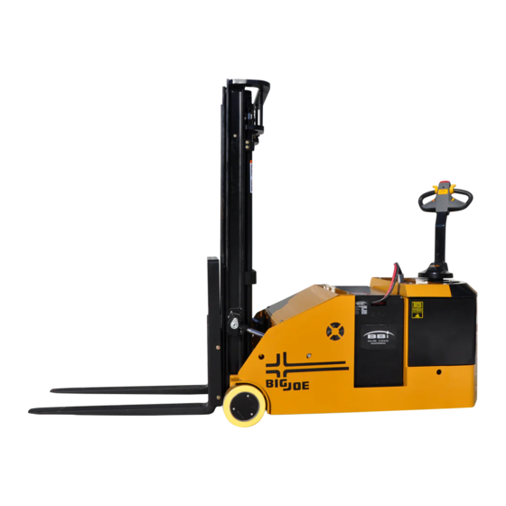
Page 6: Cb33 Lift Truck
R7242 Figure 1-2. CB33 Lift Truck ITEM COMPONENT ITEM COMPONENT Mast Chassis Back Rest Drive wheel Forks Battery Discharge Indicator Load Wheel Key Switch Hydraulic pump Control Handle Battery Battery Disconnect Controller BL-CB33-0115 - 03-01-2018... -
Page 7: Operation
This section gives detailed operating instructions for and loaded. the CB33 lift truck. The instructions are divided into the various phases of operations, such as operating lift, • Be sure that mast is vertical - do not operate on a driving, and stopping. -
Page 8: Before Operation
All Table 2-1 covers important inspection points on the service must be performed by a qualified CB33 lift truck which should be checked prior to opera- maintenance technician. tion. Depending on use, some trucks may require additional checks. -
Page 9: Sample Of Operator Check List
R6479 Figure 2-2 Sample of Operator Check List BL-CB33-0115 - 03-01-2018... -
Page 10: General Control Operation
(3, Figure 2-4) toward the operator, the switch changes the direction the opposite direction of travel and then releasing of the lift truck. it when the truck stops. Plugging is a convenient BL-CB33-0115 - 03-01-2018... -
Page 11: Control Arm Gas Spring
Turn off the key switch the control arm gas spring requires replacement. and disconnect the batteries. Charge batteries as nec- Return truck to maintenance for repair. essary. Refer to battery care instructions, SECTION 3. BL-CB33-0115 - 03-01-2018... - Page 12 NOTES BL-CB33-0115 - 03-01-2018...
-
Page 13: Planned Maintenance
3-3.1. General A voltage check from battery connector terminal to The CB33 may be equipped with maintenance free or battery case should indicate near zero volts. Typically, industrial wet cell batteries. however, the sum of the voltages at both terminals will The care and maintenance of the battery is very equal battery volts. -
Page 14: 3-3.2. Safety Rules
If batteries stay wet consistently, they may be either overcharged or over filled. This condition CAUTION: Never smoke or bring open flame near should be investigated and corrected. the battery. Gas formed during charging is highly explosive and can cause seri- ous injury. BL-CB33-0115 - 03-01-2018... -
Page 15: 3-3.5. Maintenance Free Batteries
Make sure con- watering. nectors are mated properly. Connect the charger to the appropriate power supply. Follow the instructions for the charger being used. BL-CB33-0115 - 03-01-2018... -
Page 16: Lubrication
SAE 30 or 40 engine oil. 100 SUS foam suppressing agent and rust and oxidation inhibitors (Note) No. 4 SAE 30 or 40 Engine lubricating oil NOTE: USED ON COLD CONDITIONED TRUCKS BL-CB33-0115 - 03-01-2018... -
Page 17: Lubrication Diagram
Light coating where forks slide Hydraulic Reservoir No. 3 With lift carriage fully lowered, fill Capacity-1 quarts reservoir with hydraulic oil to 1 inch below opening Transmission No. 1 Fill to level plug opening Capacity 2 pints BL-CB33-0115 - 03-01-2018... - Page 18 NOTES BL-CB33-0115 - 03-01-2018...
-
Page 19: Troubleshooting
Truck does not slow with brake, or a. Defective deadman switch. Check deadman switch for brake does not engage. continuity. If none found when the control arm is in the brake position, replace switch. b. Defective electric brake. Replace brake. BL-CB33-0115 - 03-01-2018... - Page 20 Check the oil level in the reservoir and the oil lines to the lift cylin- der, and repair as required. If normal, check the hydraulic pump, and relief valve. Repair, or adjust. Table 4-1 Troubleshooting Chart - Continued MALFUNCTION PROBABLE CAUSE CORRECTIVE ACTION BL-CB33-0115 - 03-01-2018...
- Page 21 Defective potentiometer. Check and replace potentiometer if defective. d. Defective controller. Check operation and replace if necessary. d. Defective steering motor. Check wiring and repair as required. BL-CB33-0115 - 03-01-2018...
-
Page 22: 4-1.1. Controller Troubleshooting
There are two versions shown. A Zapi Handset is available that is designed specifi- The CB33 uses the Standard version which cally for use with the Zapi controller. It serves multiple lists the error by: Alarm Name, Repetitions, functions of reading diagnostic data, testing truck Temperature and Hour Meter reading. - Page 23 CONFIG MENU. Press the OUT button to exit the parameters. Press the ROLL down button or the ROLL up but- ton to find the ADJUSTMENTS display. BL-CB33-0115 - 03-01-2018...
- Page 24 In this case, it is necessary to replace the temperature increases from controller. 85 to 105 At 105 the Cur- rent is limited to 0 Amps. BL-CB33-0115 - 03-01-2018...
- Page 25 It is just enough to turn the CHECK UP DONE NEEDED the time programmed mainte- option to level ON after the maintenance is nance executed. DATA Acquisition of the current gains. The alarm ends when the acquisition is done. ACQUISITION BL-CB33-0115 - 03-01-2018...
- Page 26 CAN the message that another controller in the net is in fault condition; as a consequence the ACOE controller itself can- not enter an operative status, but has to WAIT for the other controller coming out from the fault status. BL-CB33-0115 - 03-01-2018...
- Page 27 EV4 in the “Set Options” menu is set “PRES- ENT”, in this case the warning disappears setting the EV4 parameter “ADBSENT”. Otherwise the driver circuit is damaged and the controller must be replaced. BL-CB33-0115 - 03-01-2018...
- Page 28 (cannot replace the controller close). CONT. DRV. EV5 The EV5 valve driver is not able The device or its driving circuit is damaged, to drive the load (cannot replace the controller close). 4-10 BL-CB33-0115 - 03-01-2018...
- Page 29 ±0.25 V. LOGIC FAILURE This alarm occurs when the real It is necessary to replace the controller voltage between phases W and V of the motor is different from the desired voltage. BL-CB33-0115 - 03-01-2018 4-11...
- Page 30 150 degrees. It also occurs when trying to acquire the motor resistance with a temperature in the motor higher than 150 degree (still with DIAG MOTOR TEMP to ON). 4-12 BL-CB33-0115 - 03-01-2018...
- Page 31 STEER HAZARD This is just a warning to inform that the steering controller is limiting the angle in the steer- ing direction. No speed reduc- tion occurs on the traction. BL-CB33-0115 - 03-01-2018 4-13...
- Page 32 This alarm occurs if the current in Search for a mechanical problem locking the LOCKED the steering motor stays close motor. To help in the fault finding, set to the maximum current longer DEBUG OUTPUT to level 11. tan 1 sec. 4-14 BL-CB33-0115 - 03-01-2018...
- Page 33 This alarm occurs when the It is necessary to send the controller to Zapi to parameter to compensate for perform, the maximum current regulation. the gain of the current amplifi- ers (ADJUSTMENT #03 and ADJUSTMENT #04) have the default values. BL-CB33-0115 - 03-01-2018 4-15...
- Page 34 (the sensor bearing has two rings: one is connected to the rotor shaft; the other is connected to trhe motor frame. Check these two rings are securely con- nected to their structure without slippage. 4-16 BL-CB33-0115 - 03-01-2018...
- Page 35 DATA ACQUISI- This alarm occurs when acquir- Recycle the key. TION ing the motor resistance or when adjusting the parame- ters to compensate for the gain of the current amplifiers (maxi- mum current factory adjusted). BL-CB33-0115 - 03-01-2018 4-17...
- Page 36 (CPOC1) exits the range from 0.8 Vdc to 4.2 Vdc. When the twin pot is chosen, the alarm occurs if the sum of the two wiper voltages (CPOC1 + CPOC2) exists the range from 4.5 Vdc to 5.5 Vdc. 4-18 BL-CB33-0115 - 03-01-2018...
- Page 37 In fact, when the being commanded. safety contacts are open, NK1 is expected to be a minus battery voltage (not 12 V). Search for a harness problem or replace the controller. BL-CB33-0115 - 03-01-2018 4-19...
- Page 38 NOTES 4-20 BL-CB33-0115 - 03-01-2018...
-
Page 39: Steering System, Control Head And Compartment
5-1.1. Cap Assembly Removal. Lift up cap, tag and disconnect harness from har- Turn off the key switch and disconnect the batter- nesses in control head. ies. Remove cap. DP_0001 Figure 5-1 Control Arm BL-CB33-0115 - 03-01-2018... -
Page 40: 5-1.2. Cap Assembly Installation
As cap is installed, install cover and spring. Secure cap with screws. Hold cap in place and reconnect harness to har- Reconnect the batteries and turn on the key nesses in control handle. switch. DP_0002 Figure 5-2 Control Head BL-CB33-0115 - 03-01-2018... -
Page 41: 5-1.3. Control Head Removal
Position the opposite end of the gas return spring 5-1.7. Horn Switch Replacement. on bracket and install screw. Remove the cap assembly as described in para- Install cover and secure with three screws, lock graph 5-1.1. washers, flat washers BL-CB33-0115 - 03-01-2018... -
Page 42: 5-2.2. Control Arm Removal
Install cover, three screws, lock washers and flat paragraph 5-3. washers. Disconnect position switch from harness. Position covers on hinges. Close the covers and secure with two screws and washers. Remove position switch from the frame. Disconnect harness from steering motor. BL-CB33-0115 - 03-01-2018... -
Page 43: 5-5.2. Installation
Install position switch on the frame. Reconnect harness to position switch. 5-5.2. Installation. Install the compartment covers as described in Position steering motor on the frame and secure paragraph 5-3. with four screws. Reconnect the batteries and turn on the key switch. BL-CB33-0115 - 03-01-2018... - Page 44 NOTES BL-CB33-0115 - 03-01-2018...
-
Page 45: Brake Servicing
Install the compartment covers as described in Block load wheels. paragraph 5-3. Turn off the key switch and disconnect the batter- Reconnect the batteries and turn on the key- ies. switch. Remove the compartment covers as described in paragraph 5-3. BL-CB33-0115 - 03-01-2018... -
Page 46: Drive Assembly
DP_0004 Figure 6-1 Drive Assembly BL-CB33-0115 - 03-01-2018... -
Page 47: Transmission, Drive Wheel, Load Wheel
Remove the twelve screws, bearing and gear Remove blocking from under the truck and lower from transmission. to the ground. Install new transmission by reversing the steps Reconnect the batteries and turn on the key- above. switch. BL-CB33-0115 - 03-01-2018... -
Page 48: Drive Assembly
DP_0004 Figure 7-1 Drive Assembly BL-CB33-0115 - 03-01-2018... - Page 49 DP_0007 Figure 7-2 Load Wheels BL-CB33-0115 - 03-01-2018...
- Page 50 NOTES BL-CB33-0115 - 03-01-2018...
-
Page 51: Elevation System Servicing
Tighten jam nuts securely while maintaining align- ment of clevis pins. Reconnect the batteries and turn on the key- switch. Test chain by operating carriage. If slack is still apparent, repeat above procedure. DP_0017 Figure 8-1 Chain Assembly BL-CB33-0115 - 03-01-2018... - Page 52 DP_0008 Figure 8-2 Elevation System (Telescopic) BL-CB33-0115 - 03-01-2018...
-
Page 53: 8-2.2. Three Stage Mast Free Lift Chain
New chain anchor pins should be installed when chains are replaced. Never replace a partial section of WARNING: Before attempting any adjustment, make chain and never repair chain. Refer to paragraph 8-4. certain power is disconnected. when installing new chain. BL-CB33-0115 - 03-01-2018... - Page 54 DP_0009 Figure 8-3 Mast (Three Stage Mast) BL-CB33-0115 - 03-01-2018...
-
Page 55: Lift Chain Replacement
WARNING: Before attempting any replacement, 8-5. LIFT CYLINDERS. make certain power is disconnected. NOTE: Removal and repair of lift cylinders are cov- Remove cotter pin and clevis pin connecting ered in SECTION chain to chain anchor at the lift carriage. BL-CB33-0115 - 03-01-2018... - Page 56 NOTES BL-CB33-0115 - 03-01-2018...
-
Page 57: Hydraulic System Servicing
To Install the front compartment covers as described ensure release of pressure, forks must in paragraph 5-3. be fully lowered and the batteries discon- nected before performing any mainte- nance on the hydraulic system. BL-CB33-0115 - 03-01-2018... - Page 58 DP_0018 Figure 9-1 Hydraulic System BL-CB33-0115 - 03-01-2018...
-
Page 59: Lift Cylinder (Telescopic)
Remove screw, lock washer and flat washer, securing the top of cylinder to mast. Raise lift cylinder assembly up and out of truck. Without Side Shift DP_0037 With Side Shift DP_0019 Figure 9-2 Lift System (Telescopic) BL-CB33-0115 - 03-01-2018... - Page 60 DP_0008 Figure 9-3 Elevation System (Telescopic) BL-CB33-0115 - 03-01-2018...
-
Page 61: 9-3.2. Repair
Fill the hydraulic reservoir. Use hydraulic oil listed Table 3-2. Reconnect the batteries and turn on the key- switch. Operate the lift and lower buttons to refill the cylinders and lines with hydraulic oil. DP_0010 Figure 9-4 Lift Cylinder (Telescopic) BL-CB33-0115 - 03-01-2018... -
Page 62: Lift Cylinder (Three Stage Mast Free Lift)
Remove screw, lock washer, flat washer, bracket and ram head (8) from cylinder. WARNING: Before attempting any replacement, make certain power is disconnected. With Side Shift Without Side Shift DP_0038 DP_0020 Figure 9-5 Lift System (Three Stage Mast) BL-CB33-0115 - 03-01-2018... - Page 63 Support cylinder and remove two screws, two lock necting. washers and two flat washers. Remove chains from sheaves. Raise lift cylinder assembly up and out of truck. DP_0009 Figure 9-6 Elevation System (Three Stage Mast) BL-CB33-0115 - 03-01-2018...
-
Page 64: 9-4.2. Repair
Fill the hydraulic reservoir. Use hydraulic oil listed Table 3-2. DP_0011 Reconnect the batteries and turn on the key- switch. Operate the lift and lower buttons to refill the Figure 9-7 Free Lift Cylinder (Three Stage Mast) cylinder and lines with hydraulic oil. BL-CB33-0115 - 03-01-2018... -
Page 65: Lift Cylinder (Three Stage Mast Secondary)
10. Install the compartment covers as described in at the base of the cylinder. paragraph 5-3. Remove gland nut. Remove wiper and O-ring from gland nut. Pull out piston rod. Remove collar and piston from piston rod. BL-CB33-0115 - 03-01-2018... - Page 66 DP_0012 Figure 9-8 Secondary Lift Cylinder (Three Stage Mast) 9-10 BL-CB33-0115 - 03-01-2018...
-
Page 67: 9-5.4. Tilt Cylinders
WARNING: Before attempting any replacement, Support the tilt cylinder and remove bolt, lock make certain power is disconnected. washer, flat washer and shaft from the cylinder. Carefully raise tilt cylinder from the truck. DP_0015 Figure 9-9 Tilt Cylinder Mounting BL-CB33-0115 - 03-01-2018 9-11... - Page 68 Table 3-2. 12. Install piston rod in cylinder body. Install the front compartment covers as described 13. Install dust seal, seal and O-ring in gland nut. in paragraph 5-3. 14. Install gland nut in tube. 9-12 BL-CB33-0115 - 03-01-2018...
- Page 69 DP_0016 Figure 9-10 Tilt Cylinder BL-CB33-0115 - 03-01-2018 9-13...
- Page 70 NOTES 9-14 BL-CB33-0115 - 03-01-2018...
-
Page 71: Electrical Components
Install the compartment covers as described in Turn off the key switch and disconnect the batter- paragraph 5-3. ies. Reconnect the batteries and turn on the key- Remove the compartment covers as described in switch. paragraph 5-3. BL-CB33-0115 - 03-01-2018 10-1... - Page 72 R6478 DP_0022 Figure 10-1 Electrical System 10-2 BL-CB33-0115 - 03-01-2018...
- Page 73 R6478 DP_0023 Figure 10-2 Electrical Panel BL-CB33-0115 - 03-01-2018 10-3...
-
Page 74: 10-4.1.Motor Removal
Install cover and secure with three screws, flat washers and lock washers. Install drive motor onto bearing. Reconnect the batteries and turn on the key- Remove six screws, six lock washers and six flat switch. washers to secure the motor to the bearing. 10-4 BL-CB33-0115 - 03-01-2018... - Page 75 DP_0004 Figure 10-3 Transmission, Motor, Brake Assembly BL-CB33-0115 - 03-01-2018 10-5...
- Page 76 NOTES 10-6 BL-CB33-0115 - 03-01-2018...
- Page 77 SECTION 11 OPTIONAL EQUIPMENT BL-CB33-0115 - 03-01-2018 11-1...
- Page 78 NOTES 11-2 BL-CB33-0115 - 03-01-2018...
-
Page 79: Illustrated Parts Breakdown
SECTION 12 ILLUSTRATED PARTS BREAKDOWN Following is an illustrated parts breakdown of assemblies and parts associated with the CB33 Lift Truck. BL-CB33-0115 - 03-01-2018 12-1... - Page 80 DP_0001 Figure 12-1 Steering System 12-2 BL-CB33-0115 - 03-01-2018...
- Page 81 Used up to serial # 2130-300001-00 TURNING BRACKET D24140023 Used from serial # 2333-300001-00 TURNING BRACKET D24140024 2130-350000-00 GAS SPRING 1120-300006-00 SPACER 0000-000028-00 SCREW, M4 X 10 0000-000122-00 WASHER, LOCK, M4 0000-000702-00 WASHER, FLAT, M4 0000-000011-00 BEARING 1120-300003-00 SHAFT BL-CB33-0115 - 03-01-2018 12-3...
- Page 82 DP_0001 Figure 12-1 Steering System - Continued 12-4 BL-CB33-0115 - 03-01-2018...
- Page 83 Used from serial # 2333-520002-1B WIRE HARNESS S2221338 0000-000429-00 SCREW, M5 X 8 2130-520004-00 SWITCH WIRE HARNESS 0000-000377-00 SCREW, M2 X 20 1221-300003-00 ROCKER POTENTIOMETER 1221-300004-00 PLATE 1220-560001-00 SWITCH 0000-000121-00 SCREW, M4 X 35 1221-300001-00 2333-320000-10 CONTROL HANDLE BRACKET BL-CB33-0115 - 03-01-2018 12-5...
- Page 84 DPP_0002 Figure 12-2 Control Head 12-6 BL-CB33-0115 - 03-01-2018...
- Page 85 2333-340013-00 SCREW, M5 X 30 2333-340014-00 SCREW, M5 X 55 2333-340018-00 BRACKET 2333-340019-00 SCREW, M3 X 10 2333-340020-00 COVER 2333-340022-00 SEALING PLATE 2333-340023-00 BUTTON 2333-340024-00 SCREW M5 x 12 2333-340025-00 SCREW ST2.9×20 2333-340026-00 BUSHING 2333-340027-00 BUSHING BL-CB33-0115 - 03-01-2018 12-7...
- Page 86 DP_0035 Figure 12-3 Control Head when Side Shift option 12-8 BL-CB33-0115 - 03-01-2018...
-
Page 87: Control Head
SCREW, M5 X 30 2333-340014-00 SCREW, M5 X 55 2333-340018-00 BRACKET 2333-340019-00 SCREW, M3 X 10 2333-340020-00 COVER 2333-340022-00 SEALING PLATE 2333-340023-00 BUTTON 2333-340024-00 SCREW M5 x 12 2333-340025-00 SCREW ST2.9×20 2333-340016-00 SIDE SHIFT BUTTON 2333-340026-00 BUSHING 2333-340027-00 BUSHING BL-CB33-0115 - 03-01-2018 12-9... - Page 88 DP_0003 Figure 12-4 Drive System 12-10 BL-CB33-0115 - 03-01-2018...
-
Page 89: Drive System
DRIVE ASSEMBLY S2410419 Used between serial # 2333-200000-1A DRIVE ASSEMBLY S2410420 and 325130600 Used between serial # 2333-200000-1B DRIVE ASSEMBLY 325130601 and 326140869 Used from serial # 2333-200000-1C DRIVE ASSEMBLY 326140870 1280-520009-10 POSITION SWITCH WIRE HARNESS BL-CB33-0115 - 03-01-2018 12-11... - Page 90 DP_0004 Figure 12-5 Drive Assembly - Used up to serial # S2410419 12-12 BL-CB33-0115 - 03-01-2018...
-
Page 91: Drive Motor
WASHER, LOCK, M14 0000-001269-10 NUT, M14 X 1.5 2333-270000-10 STEERING MOTOR 2333-200004-00 GEAR 0000-000321-00 SCREW, M8 X 20 0000-000386-00 SCREW, M6 X 20 0000-000056-00 WASHER, LOCK, M6 2333-200001-10 WASHER 2333-210001-10 BRAKE LINING 0000-001287-10 SCREW, M6 X 70 BL-CB33-0115 - 03-01-2018 12-13... - Page 92 DP_0028 Figure 12-6 Drive Assembly - Used between serial # S2410420 and 325130600 12-14 BL-CB33-0115 - 03-01-2018...
- Page 93 ELASTIC COLLAR 0000-000322-00 SCREW M8×25 0000-000159-00 LOCKWASHER Ø8 CK10-240000-20 STEERING MOTOR 1280-210042-10 MOTOR GEAR 2415-220000-10 GEAR CASE ASSEMBLY 2415-230000-10 DRIVE WHEEL 0000-000283-00 BOLT M10×35 0000-000063-00 LOCKWASHER Ø10 0000-001281-00 SCREW M8×75 0000-000176-00 FLATWASHER Ø8 CK10-240001-20 KB-SENSOR, STEERING MOTOR BL-CB33-0115 - 03-01-2018 12-15...
- Page 94 DP_0032 Figure 12-7 Drive Assembly - Used from serial # 325130601 12-16 BL-CB33-0115 - 03-01-2018...
- Page 95 326140869 Used from serial # ZK18-240000-A0-02 GEAR CASE ASSEMBLY 326140870 2415-230000-1A DRIVE WHEEL 0000-001131-10 NUT M12×1.5 0000-000025-00 LOCKWASHER Ø12 0000-001281-00 SCREW M8×75 0000-000176-00 FLATWASHER Ø8 CK10-240001-20 KB-SENSOR,STEERING MOTOR 1120-240014-3A STUDS 0000-001287-10 SCREW M6x70 2333-210004-00 BRAKE LINING BL-CB33-0115 - 03-01-2018 12-17...
- Page 96 DP_0029 Figure 12-8 Gear Case Assembly - Used between serial # S2410420 and 326140869 12-18 BL-CB33-0115 - 03-01-2018...
- Page 97 FLATWASHER Ø14 0000-001055-00 WASHER Ø14 0000-001056-00 NUT M14×1.5 2415-220014-10 SEAL WASHER Used between serial # 2415-220003-10 OUTPUT SHAFT S2410420 and 325130600 2415-220003-1A OUTPUT SHAFT Used from serial # 325130601 2415-220018-10 COVER PLATE 2415-220010-10 SEAT 0000-001285-10 BEARING BL-CB33-0115 - 03-01-2018 12-19...
- Page 98 DP_0029 Figure 12-8 Gear Case Assembly - Used between serial # S2410420 and 326140869 - Continued 12-20 BL-CB33-0115 - 03-01-2018...
- Page 99 BOLT M8×20 0000-001699-00 SNAP RING ø55 2415-220015-10 SEAL WASHER 0000-000762-00 ELASTIC COLLAR Ø62 0000-000183-00 RETAINER RING Ø35 0000-001282-10 BEARING 2415-220011-10 SLEEVE 2415-220013-10 GEAR 0000-000321-00 SCREW M8×20 0000-001286-10 BEARING 0000-001283-10 BEARING 2415-220016-10 RING WIPER VL-160 2415-220017-10 DUST COVER BL-CB33-0115 - 03-01-2018 12-21...
- Page 100 DP_0042 Figure 12-9 Gear Case Assembly - Used from serial # 326140870 12-22 BL-CB33-0115 - 03-01-2018...
- Page 101 ELASTIC COLLAR Ø62 0000-001056-00 NUT M14×1.5 0000-000070-00 SCREW M10×25 0000-000379-00 FLATWASHER Ø14 0000-001055-00 WASHER Ø14 ZK18-240008-00 COVER 0000-000056-00 LOCKWASHER Ø6 0000-000077-00 SCREW M6×12 0000-000055-00 SCREW M6×16 0000-001054-00 BEARING ZK18-240005-00 COVER 0000-001789-00 O-RING 155×4 ZK18-240003-00 GEAR CASE BL-CB33-0115 - 03-01-2018 12-23...
- Page 102 DP_0042 Figure 12-9 Gear Case Assembly - Used from serial # 326140870 - Continued 12-24 BL-CB33-0115 - 03-01-2018...
- Page 103 Description Notes Reqd. ZK18-GB00-10 GEAR KIT (Z1/Z2=6/43) ZK18-240007-00 OUTPUT SHAFT 0000-001790-00 BEARING 0000-001791-00 ELASTIC COLLAR Ø140 0000-001792-00 RETAINER RING Ø100 0000-001787-00 SEAL WASHERTC140*100*12 ZK12-240011-00 WASHER A.R. As Required 0000-000321-00 SCREW M8×20 0000-000159-00 LOCKWASHER Ø8 ZK18-240015-00 GEAR BL-CB33-0115 - 03-01-2018 12-25...
- Page 104 DP_0005 Figure 12-10 Compartment 12-26 BL-CB33-0115 - 03-01-2018...
-
Page 105: Compartment
0000-000109-00 SCREW, M8 X 16 0000-000159-00 WASHER, LOCK, M8 0000-000194-00 WASHER, FLAT, M8 2125-600005-00 BUFFER BLOCK 2214-150002-00 WASHER 2333-130001-00 MOUNTING PLATE 1146-151002-30 MANUAL HOLDER Used from serial num- 0000-000119-00 SCREW M5x12 ber 326110894 0000-000546-00 NUT M5 BL-CB33-0115 - 03-01-2018 12-27... - Page 106 DP_0006 Figure 12-11 Frame 12-28 BL-CB33-0115 - 03-01-2018...
-
Page 107: Frame
Used up to serial # 2333-110000-10 FRAME S2410419 Used from serial # 2333-110000-1A FRAME S2410420 1280-161000-00 ROLLER FRAME 1280-160001-00 ROLLER 0000-000322-00 SCREW, M8 X 25 Used up to serial # 1280-180002-00 BAFFLE S2410158 Used from serial # 2333-180001-00 BAFFLE S2410159 BL-CB33-0115 - 03-01-2018 12-29... - Page 108 DP_0006 Figure 12-11 Frame - Continued 12-30 BL-CB33-0115 - 03-01-2018...
- Page 109 FRAME - CONTINUED Qty. Pos. Part Number Description Notes Reqd. 1280-180001-0A BLOCK 0000-000279-00 BOLT, M8 X 35 2125-100002-00 BATTERY CLIP 2140-100001-00 BATTERY BLOCK BL-CB33-0115 - 03-01-2018 12-31...
- Page 110 DP_0007 Figure 12-12 Load Wheels 12-32 BL-CB33-0115 - 03-01-2018...
-
Page 111: Load Wheels
WASHER, LOCK, M6 0000-000380-00 WASHER, FLAT, M6 2320-600002-00 RETAINER 2320-601100-00 LOAD WHEEL 2320-600001-00 MOUNTING BASE 0000-000379-00 WASHER, FLAT, M14 0000-000233-00 WASHER, LOCK, M14 0000-001028-00 BOLT, M14 X 90 0000-000858-00 BUSHING, 50 X 60 X 30 0000-000857-00 BEARING BL-CB33-0115 - 03-01-2018 12-33... - Page 112 DP_0008 Figure 12-13 Elevation System (Telescopic) 12-34 BL-CB33-0115 - 03-01-2018...
-
Page 113: Elevation System (Telescopic)
Used for Lift Height 2333-620000-00-01 INNER MAST 104” Used for Lift Height 2333-620000-20-01 INNER MAST 104” When Side Shift Used for Lift Height 2333-620000-00-03 INNER MAST 126” Used for Lift Height 2333-620000-20-03 INNER MAST 126” When Side Shift BL-CB33-0115 - 03-01-2018 12-35... - Page 114 DP_0008 Figure 12-13 Elevation System (Telescopic) - Continued 12-36 BL-CB33-0115 - 03-01-2018...
-
Page 115: Elevation System (Telescopic)
PROXIMITY SWITCH HARNESS 0000-000004-00 SCREW, M5 X 12 2125-500003-00 PROXIMITY SWITCH 8108 0000-000390-00 WASHER, FLAT, M5 0000-000206-00 WASHER, LOCK, M5 0000-000632-00 BOLT M12×80 0000-000222-00 FLATWASHER Ø12 Used when Side Shift 2125-600002-30 OIL PIPE ROLLER 2125-600003-00 BUSHING BL-CB33-0115 - 03-01-2018 12-37... - Page 116 DP_0009 Figure 12-14 Elevation System (Three Stage Mast) 12-38 BL-CB33-0115 - 03-01-2018...
-
Page 117: Elevation System (Three Stage Mast)
For Lift Height 157” - When Side 2333-620000-40-01 MIDDLE MAST Shift 0000-000613-00 BOLT, M12 X 50 0000-000222-00 WASHER, FLAT, M12 2125-600002-30 HOSE ROLLER 2125-600003-00 BUSHING 2333-630000-30-01 INNER MAST For Lift Height 157” For Lift Height 157” -When Side 2333-630000-40-01 INNER MAST Shift BL-CB33-0115 - 03-01-2018 12-39... - Page 118 DP_0009 Figure 12-14 Elevation System (Three Stage Mast) - Continued 12-40 BL-CB33-0115 - 03-01-2018...
-
Page 119: Elevation System (Three Stage Mast)
PROXIMITY SWITCH HARNESS For Lift Height 157” 0000-000919-00 Bolt M12×65 K25S100007-Y Double Tube Round 3215-800002-30 Tube Axle 3215-800001-30 Plate 3215-800004-30 Fixed Plate When Side Shift 3215-800005-30 Bracket 3215-800006-30 Middle Tube Round 3215-800003-30 Tube Axle 0000-000242-00 Bolt M8×16 BL-CB33-0115 - 03-01-2018 12-41... - Page 120 DP_0009 Figure 12-14 Elevation System (Three Stage Mast) - Continued ELEVATION SYSTEM (THREE STAGE MAST) - CONTINUED 12-42 BL-CB33-0115 - 03-01-2018...
- Page 121 Qty. Pos. Part Number Description Notes Reqd. 2333-500001-50 Board CK10-520015-10 Warning Light 2333-520007-50 Warning Light Wiring Optional 0000-000139-00 Nut M4 0000-000122-00 Lockwasher ø4 BL-CB33-0115 - 03-01-2018 12-43...
-
Page 122: Lift Carriage (Telescopic)
DP_0013 Figure 12-15 Lift Carriage (Telescopic) LIFT CARRIAGE (TELESCOPIC) 12-44 BL-CB33-0115 - 03-01-2018... - Page 123 WASHER, FLAT, M12 2320-631000-00 BACKREST 2130-631000-00 LIFT CARRIAGE 2130-631000-10 LIFT CARRIAGE When Side Shift option 2125-630001-00 FORK 2125-630001-10 PIN ASSEMBLY 2125-612000-00 ROLLER ASSEMBLY 0000-000030-00 SCREW, M10 X 16 2130-641000-40 SIDE SHIFT ASSEMBLY When Side Shift option BL-CB33-0115 - 03-01-2018 12-45...
- Page 124 DP_0014 Figure 12-16 Lift Carriage (Three Stage Mast) 12-46 BL-CB33-0115 - 03-01-2018...
-
Page 125: Lift Carriage (Three Stage Mast)
Used between serial 0000-000109-00 SCREW M8×16 number 324170307 and 324200418 Used between serial 0000-000159-00 LOCKWASHER Ø8 number 324170307 and 324200418 Used between serial 0000-000176-00 FLATWASHER Ø8 number 324170307 and 324200418 2130-641000-40 SIDE SHIFT ASSEMBLY When Side Shift option BL-CB33-0115 - 03-01-2018 12-47... - Page 126 DP_0034 Figure 12-17 Side Shift Assembly 12-48 BL-CB33-0115 - 03-01-2018...
- Page 127 LUBRICATION FITTING M6 2130-641003-40 SIDE SHIFT PLATE, UPPER 0000-001425-00 ROLL PIN M5 X 40 2130-641004-40 LOCKING BLOCK 2130-641005-40 LOWER SLIDE PLATE 0000-000996-00 BOLT M16×45 0000-000220-00 WASHER 0000-001261-00 2130-ZWCYG-0A SEAL KIT OF CYLINDER 2130-ZWHK-0A PLASTIC SLIDE PLATE BL-CB33-0115 - 03-01-2018 12-49...
- Page 128 DP_0017 Figure 12-18 Chain Assembly 12-50 BL-CB33-0115 - 03-01-2018...
-
Page 129: Chain Assembly
(MOUNTS TO FREE LIFT CYL) Three Stage Mast CHAIN II Used for Lift Height 157”, 2125-652000-30-01 (MOUNTS TO INNER MAST) Three Stage Mast 2125-640003-00 CHAIN ANCHOR 0000-000686-00 COTTER PIN, M3.2 X 32 0000-000176-00 WASHER, FLAT, M8 BL-CB33-0115 - 03-01-2018 12-51... - Page 130 DP_0018 Figure 12-19 Hydraulic System - Used up to serial number 324190319 (not with Side Shift) 12-52 BL-CB33-0115 - 03-01-2018...
-
Page 131: Hydraulic System
3218-710500-00 MANIFOLD 2702-141600-00 CONNECTOR, G1/4-M16 X 1.5 0000-000044-00 SEAL, M14 0000-000322-00 SCRREW, M8 X 25 0000-000159-00 WASHER, LOCK, M8 2707-141400-00 CONNECTOR, G1/4-M14 X 1.5 2402-143500-00 BOLT, G1/4 X 35 2333-450000-00 HOSE 2402-143700-00 BOLT, G1/4 X 37 BL-CB33-0115 - 03-01-2018 12-53... - Page 132 DP_0031 Figure 12-20 Hydraulic System - Used from serial number 324190320 (Not with Side Shift) 12-54 BL-CB33-0115 - 03-01-2018...
- Page 133 2333-420000-00 OIL PIPE 2333-430000-00 OIL PIPE 3218-711000-00 OIL PIPE,TILTING 3218-710500-00 BLOCK CROSS,TILTING 2702-141600-00 CONNECTOR G1/4-M16X1.5 0000-000044-00 WASHER Ø14 0000-000322-00 SCREW M8×25 0000-000159-00 LOCKWASHER Ø8 2702-122000-00 CONNECTOR G1/2-M20X1.5 2401-204500-00 BOLT M20×45 2333-434000-30 OIL PIPE 0000-000366-00 WASHER Ø22 BL-CB33-0115 - 03-01-2018 12-55...
- Page 134 DP_0036 Figure 12-21 Hydraulic System - Used with Side Shift 12-56 BL-CB33-0115 - 03-01-2018...
- Page 135 2333-420000-00 OIL PIPE 2333-430000-00 OIL PIPE 3218-711000-00 OIL PIPE,TILTING 3218-710500-00 BLOCK CROSS,TILTING 2702-141600-00 CONNECTOR G1/4-M16X1.5 0000-000044-00 WASHER Ø14 0000-000322-00 SCREW M8×25 0000-000159-00 LOCKWASHER Ø8 2702-122000-00 CONNECTOR G1/2-M20X1.5 2401-204500-00 BOLT M20×45 2333-434000-30 OIL PIPE 0000-000366-00 WASHER Ø22 BL-CB33-0115 - 03-01-2018 12-57...
- Page 136 DP_0015 Figure 12-22 Tilt System 12-58 BL-CB33-0115 - 03-01-2018...
-
Page 137: Tilt System
0000-000159-00 WASHER, LOCK, M8 0000-000176-00 WASHER, FLAT, M8 2333-400001-00 SHAFT Used up to Serial Num- 2333-440000-00 TILT CYLINDER ber 324170306 Used from Serial Num- 2333-440000-0A TILT CYLINDER ber 324170307 0000-000321-00 SCREW, M8 X 20 3218-840000-00 SHAFT BL-CB33-0115 - 03-01-2018 12-59... - Page 138 DP_0019 Figure 12-23 Lift System (Telescopic - Not with Side Shift) 12-60 BL-CB33-0115 - 03-01-2018...
-
Page 139: Lift System (Telescopic)
PLUG, M20 X 1.5 ber 324190320 0000-000169-00 SCREW, M8 X 30 CONECTOR, 2701-161600-00 M16 X 1.5 X M16 X 1.5 Used up to serial num- 0000-000044-00 SEAL, M14 ber 324190319 Used from serial num- 0000-000510-00 SEAL, M20 ber 324190320 BL-CB33-0115 - 03-01-2018 12-61... - Page 140 DP_0037 Figure 12-24 Lift System (Telescopic - With Side Shift) 12-62 BL-CB33-0115 - 03-01-2018...
- Page 141 Metal Tube 2333-432000-20-01 Oil Pipe Used with Lift Height 104” 2333-432000-20-03 Oil Pipe Used with Lift Height 126” 3215-860300-10 Connector M14×1.5-M14×1.5 2130-450000-10 Oil Pipe 2706-141400-00 Connector M14×1.5-M14×1.5 0000-000109-00 Screw M8×16 0000-000159-00 Lockwasher ø8 0000-000176-00 Flatwasher ø8 BL-CB33-0115 - 03-01-2018 12-63...
- Page 142 DP_0020 Figure 12-25 Lift System (Three Stage Mast - Not with Side Shift) 12-64 BL-CB33-0115 - 03-01-2018...
-
Page 143: Lift System (Three Stage Mast)
TUBE ASSEMBLY 324190320 2706-162000-10 CONNECTOR, M16 X 1.5 X M20 X 1.5 Used up to serial number 2125-440000-3A-01 HOSE 324190319 Used from serial number 12a 2333-433000-30-01 HOSE 324190320 0000-000109-00 SCREW M8×16 0000-000159-00 LOCKWASHER Ø8 0000-000176-00 FLATWASHER Ø8 BL-CB33-0115 - 03-01-2018 12-65... - Page 144 DP_0038 Figure 12-25 Lift System (Three Stage Mast - with Side Shift) 12-66 BL-CB33-0115 - 03-01-2018...
- Page 145 2333-433000-30-01 HOSE 0000-000109-00 SCREW M8×16 0000-000159-00 LOCKWASHER Ø8 0000-000176-00 FLATWASHER Ø8 3215-860100-30 FOUR WAY VALVE 2130-440000-40-01 OIL PIPE 3215-860200-30 METAL TUBE 2333-431000-40-01 OIL PIPE 3215-860500-30 METAL TUBE 0000-000044-00 WASHER Ø14 2130-430000-40 OIL PIPE 2701-141400-00 CONNECTOR M14×1.5-M14×1.5 BL-CB33-0115 - 03-01-2018 12-67...
- Page 146 DP_0010 Figure 12-26 Lift Cylinder (Telescopic) 12-68 BL-CB33-0115 - 03-01-2018...
-
Page 147: Lift Cylinder (Telescopic)
Used for Lift Height 126” 2130-410003-00 COLLAR 2130-410004-00 RING, BACK UP 2130-410002-00 PISTON 0000-000132-00 ROD PACKING, 30 X 40 X 6 2130-411000-00-01 CYLINDER TUBE Used for Lift Height 104” 2130-411000-00-02 CYLINDER TUBE Used for Lift Height 126” 2125-410006-30 BL-CB33-0115 - 03-01-2018 12-69... - Page 148 DP_0011 Figure 12-27 Free Lift Cylinder (Three Stage Mast) 12-70 BL-CB33-0115 - 03-01-2018...
-
Page 149: Free Lift Cylinder (Three Stage Mast)
2130-420003-30 RING, BACK UP, 70 x 65 x 20 0000-000698-00 SNAP RING, 53 x 63 x 2 0000-000699-00 ROD PACKING, 53 X 63 X 6 Used for Lift Height 157”, 2333-421000-30-01 CYLINDER TUBE Three Stage Mast BL-CB33-0115 - 03-01-2018 12-71... - Page 150 DP_0012 Figure 12-28 Secondary Lift Cylinder (Three Stage Mast) 12-72 BL-CB33-0115 - 03-01-2018...
-
Page 151: Secondary Lift Cylinder (Three Stage Mast)
Used for Lift Height 157”, 2130-410001-30-01 PISTON ROD Three Stage Mast 2130-410003-30 COLLAR 2130-410004-30 RING, BACK UP 2130-410002-30 PISTON 0000-000132-00 ROD PACKING, 30 X 40 X 6 Used for Lift Height 157”, 2130-411000-30-01 CYLINDER TUBE Three Stage Mast 2125-410006-30 BL-CB33-0115 - 03-01-2018 12-73... - Page 152 DP_0016 Figure 12-29 Tilt Cylinder - Used up to Serial Number 324170306 12-74 BL-CB33-0115 - 03-01-2018...
-
Page 153: Tilt Cylinder
SEAL, 30 X 43 X 7 2320-440001-00 GUIDE RING 0000-000967-00 0-RING, 80 X 3.1 2320-442000-00 PISTON ROD 0000-001015-00 SEAL, YX70 X 80 X 6 2320-440003-00 WEAR RING, 20 X 2.5 2333-441000-00 CYLINDER BODY 3218-810007-00 BUSHING 0000-000588-00 GREASE FITTING BL-CB33-0115 - 03-01-2018 12-75... - Page 154 DP_0033 Figure 12-30 Tilt Cylinder - Used from Serial Number 324170307 12-76 BL-CB33-0115 - 03-01-2018...
- Page 155 SEAL, 30 X 43 X 7 2320-440001-00 GUIDE RING 0000-000967-00 0-RING, 80 X 3.1 2333-442000-0A PISTON ROD 0000-001015-00 SEAL, YX70 X 80 X 6 2320-440003-00 WEAR RING, 20 X 2.5 2333-441000-0A CYLINDER BODY 3218-810007-00 BUSHING 0000-000588-00 GREASE FITTING BL-CB33-0115 - 03-01-2018 12-77...
- Page 156 DP_0021 Figure 12-31 Pump and Motor - Not when Side Shift 12-78 BL-CB33-0115 - 03-01-2018...
- Page 157 Used up to serial number 2320-421014-00 MANIFOLD 324190319 Used between serial number 2333-470001-00 MANIFOLD 324190320 and 326120515 Used from serial number 2333-470001-1A MANIFOLD 326120516 2320-421015-00 O-RING 2125-430006-00 SEAL KIT 2125-430007-00 FILTER SCREEN 0000-000077-00 SCREW M6×12 2130-430007-0A CABLE INSULATED BL-CB33-0115 - 03-01-2018 12-79...
- Page 158 DP_0039 Figure 12-32 Pump and Motor - When Side Shift 12-80 BL-CB33-0115 - 03-01-2018...
- Page 159 2125-430005-00 COUPLING 2320-421018-00 RELIEF VALVE 2320-421001-00 ADAPTER Used up to serial number 2333-421001-40 MANIFOLD 326120515 Used from serial number 2333-422001-40 MANIFOLD 326120516 2320-421015-00 O-RING 2125-430006-00 SEAL KIT 2125-430007-00 FILTER SCREEN 0000-000077-00 SCREW M6×12 2130-430007-0A CABLE INSULATED BL-CB33-0115 - 03-01-2018 12-81...
-
Page 160: Electrical System
DP_0022 Figure 12-33 Electrical System ELECTRICAL SYSTEM 12-82 BL-CB33-0115 - 03-01-2018... -
Page 161: Electrical Panel
0000-000056-00 WASHER, LOCK, M6 2333-531000-00 BATTERY CONNECTOR 1120-112008-00 SPACER 1120-500003-00 HORN 0000-000121-00 SCREW, M4 X 35 0000-000122-00 WASHER, LOCK, M4 0000-000702-00 WASHER, FLAT, M4 1220-520010-0C 1220-500004-00 FAN GUARD 3712-405000-00 ALARM BUZZER Optional 0000-000433-00 SCREW M8×12 Optional BL-CB33-0115 - 03-01-2018 12-83... - Page 162 DP_0023 Figure 12-34 Electrical Panel 12-84 BL-CB33-0115 - 03-01-2018...
-
Page 163: Electrical Panel
SCREW, M6 X 16 1280-560002-00-30 CONTROLLER, AC 1120-540001-00-B FUSE BLOCK 1280-510002-00 BUSS BAR 1280-510001-00 BUSS BAR 0000-000015-00 SCREW, M6 X 10 1120-530006-00 BUSS BAR 1280-560003-00 CONTACTOR 0000-000159-00 WASHER, LOCK, M8 0000-000176-00 WASHER, FLAT, M8 1280-510000-10 PANEL 1280-510002-10 BUSS BAR BL-CB33-0115 - 03-01-2018 12-85... - Page 164 DP_0024 Figure 12-35 Wire Harness - Used up to Serial Number S2221337 12-86 BL-CB33-0115 - 03-01-2018...
-
Page 165: Wire Harness
WIRE HARNESS - USED UP TO SERIAL NUMBER S2221337 Qty. Pos. Part Number Description Notes Reqd. 2333-520001-00 WIRE HARNESS 1120-500010-00 FUSE, 10A BL-CB33-0115 - 03-01-2018 12-87... - Page 166 DP_0040 Figure 12-36 Wire Harness - Used from Serial Number S2221338 12-88 BL-CB33-0115 - 03-01-2018...
- Page 167 WIRE HARNESS - USED FROM SERIAL NUMBER S2221338 Qty. Pos. Part Number Description Notes Reqd. Used from serial # 2333-520001-10 WIRE HARNESS S2221338 2333-520001-50 WIRE HARNESS Used when Side Shift 1120-500010-00 FUSE, 10A BL-CB33-0115 - 03-01-2018 12-89...
- Page 168 DP_0025 Figure 12-37 Wiring Cables 12-90 BL-CB33-0115 - 03-01-2018...
- Page 169 DRIVE MOTOR CABLE W 2333-530004-00 PUMP MOTOR CABLE + 2333-530005-00 PUMP MOTOR CABLE - 2333-530006-10 STREEING MOTOR CABLE U 2333-530007-10 STREEING MOTOR CABLE V 2333-530008-10 STREEING MOTOR CABLE W 2333-530009-00 B- CABLE, CONTROLLER 2333-531000-00 BATTERY CONNECTOR BL-CB33-0115 - 03-01-2018 12-91...
- Page 170 Big Lift LLC...
Need help?
Do you have a question about the CB33 and is the answer not in the manual?
Questions and answers