Raven VSN Installation Manual
For agco rogator c
Hide thumbs
Also See for VSN:
- Operation manual (57 pages) ,
- Installation manual (30 pages) ,
- Installation manual (28 pages)

Related Manuals for Raven VSN


Summary of Contents for Raven VSN
- Page 1 VSN Installation Manual for AGCO RoGator C 016-2023-002 Rev. A 10/2019 E33210 Copyright 2019...
- Page 2 Raven systems, or products used as components of systems, which rely upon the reception of these signals or availability of these services. Raven Industries accepts no responsibility for the use of any of these signals or services for other than the stated purpose.
-
Page 3: Table Of Contents
Point of Reference .................................. 5 Updates ...................................6 Kit Contents ...................................6 Chapter 3 Installation ....................... 9 Mounting VSN ................................9 Cabling and Connection ............................12 VSN Cab Cable ..................................13 VSN Camera Cable ................................18 Optional Ethernet Cable ..............................19 Reflective Decals ...................................20 016-2023-002 Rev. A... - Page 4 Table of Contents VSN Installation Manual for AGCO RoGator C...
-
Page 5: Important Safety Information
• Do not operate VSN or any agricultural equipment while under the influence of alcohol or an illegal substance. • Remain in the operator’s position or a safe working distance away from the booms at all times when VSN is engaged. -
Page 6: General
Allow sufficient clearance from machine component operational zones such as: • Drive shafts, universal joints and hitches (i.e. 3-point hitch) • Pulleys, gears, sprockets • Deflection and backlash of belts and chains • Adjustment zones of adjustable brackets VSN Installation Manual for AGCO RoGator C... - Page 7 IMPORTANT SAFETY INFORMATION • Changes of position in RS1 HD and suspension systems • Moving linkages, cylinders, articulation joints, attachments • Ground engaging components For harness sections that move during machine operation: • Allow sufficient length for free movement without interference to prevent: pulling, pinching, catching or rubbing, especially in articulation and pivot points •...
- Page 8 CHAPTER 1 VSN Installation Manual for AGCO RoGator C...
-
Page 9: Chapter 2 Introduction
Calibration & Operation Manual (P/N 016-2020-001) for assistance with calibrating and using the VSN system. PREPARING FOR INSTALLATION Before installing the VSN system, park the machine where the ground is level, clean, and dry. Turn off the machine and leave it turned off for the duration of the installation process. -
Page 10: Updates
KIT CONTENTS This section contains a list of the components that are included in the VSN kit. Before beginning the system installation, compare the items in the kit with the components on this list. If you have questions about the kit, contact your Raven dealer. - Page 11 INTRODUCTION FIGURE 1. VSN Installation Kit for AGCO RoGator C Introduction: Kit Contents...
- Page 12 CHAPTER 2 VSN Installation Manual for AGCO RoGator C...
-
Page 13: Installation
1. Locate the rubber boom cushion or boom cradle bracket mounted to the top of the right boom cradle. 2. Loosen the hardware holding the cushion or cradle bracket to the cradle frame. FIGURE 1. Cradle Frame Cushion Hardware Loosen Hardware Installation: Mounting VSN... - Page 14 3/8”-16 U-Bolt, Flanged Locknut x2 4. Using the provided 3/8” flanged lock nuts, secure the VSN base bracket to the cradle framework. 5. Retighten the hardware holding the cushion or cradle bracket to the cradle frame. VSN Installation Manual for AGCO RoGator C...
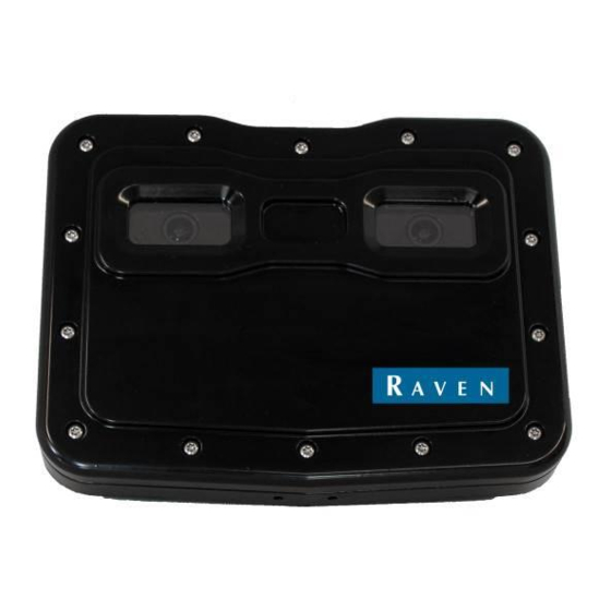
- Page 15 INSTALLATION 6. Using the provided M8 hardware, mount the debris shield and brackets to the back of the VSN camera as shown in Figure 4 on page 11. NOTE: The camera must be mounted with the lens at the top when mounted to the equipment.
-
Page 16: Cabling And Connection
CHAPTER 3 CABLING AND CONNECTION FIGURE 6. VSN Steering System Diagram for AGCO RoGator C VSN Installation Manual for AGCO RoGator C... -
Page 17: Vsn Cab Cable
INSTALLATION VSN CAB CABLE 1. Locate and remove the exterior access panel on the right, rear of the cab. FIGURE 7. Exterior Cab Access Panel Removed from Right Rear 2. Locate and punch out one pass-through provision inside the access panel to provide access into the cab. - Page 18 CHAPTER 3 FIGURE 8. Pass-Through Provisions inside Right Rear Access Panel Pass-Through 3. On the interior of the vehicle cab, locate and remove the access panels along the right side of the cab. VSN Installation Manual for AGCO RoGator C...
- Page 19 FIGURE 9. Interior Access Panels Removed from Right Rear Panels Removed 4. Route the 7-pin bulkhead connector on the VSN Cab cable (P/N 115-2020-008) into the interior access panel and secure to the bulkhead in the removed pass-through provision using the jam nut provided on the connector.
- Page 20 CHAPTER 3 FIGURE 10. Bulkhead Access Point Cab Cable Bulkhead Connector Connector Jam Nut 5. Route the remaining end of the cab cable to the Viper 4 and connect to Port 6. VSN Installation Manual for AGCO RoGator C...
- Page 21 INSTALLATION FIGURE 11. Viper 4 Connection Installation: Cabling and Connection...
-
Page 22: Vsn Camera Cable
CHAPTER 3 VSN CAMERA CABLE 1. Route the end of the VSN camera cable (P/N 115-2020-007) with the round 35 pin connectors up through the opening at the bottom of the area behind the exterior access panel. 2. Locate and disconnect the four round bulkhead connections labeled X3, X4, X5 and X6 to gain access to the power connections and the X4 Cab #4 connection. -
Page 23: Optional Ethernet Cable
10. Disconnect the 12-pin connector and tee in the connector breakouts labeled SW PWR TEE. OPTIONAL ETHERNET CABLE 1. Connect the blue/green Ethernet cable to the back of the VSN camera. 2. Route the Ethernet cable along the frame and up to the RS1. -
Page 24: Reflective Decals
The included decals (P/N 041-0159-940) must be installed on the boom cradle or machine frame to restore and maintain visibility after the VSN assembly is mounted. Trim the decals as needed to fit the location to which each will be affixed. - Page 25 Index Important Safety Information Electrical Safety General 2 Instructions for Wire Routing 2 Introduction Kit Contents Preparing for Installation Point of Reference 5 Recommendations 5 Updates Kit Contents 016-2023-002 Rev. A...
- Page 26 Index VSN Installation Manual for AGCO RoGator C...
- Page 27 Bring the defective part and proof of purchase to your Raven dealer. If the dealer approves the warranty claim, the dealer will process the claim and send it to Raven Industries for final approval. The freight cost to Raven Industries will be the customer’s responsibility.
- Page 28 Bring the defective part and proof of purchase to your Raven dealer. If the dealer approves the warranty claim, the dealer will process the claim and send it to Raven Industries for final approval. The freight cost to Raven Industries will be the customer’s responsibility.
Need help?
Do you have a question about the VSN and is the answer not in the manual?
Questions and answers